
Subscribe to Our Youtube Channel
Related Manuals for GESTRA LRR 1-40


Summary of Contents for GESTRA LRR 1-40
- Page 1 Control Unit LRR 1-40 Original Installation Instructions 818527-03 E n g l i s h...
-
Page 2: Table Of Contents
ATEX (Atmosphère Explosible) .........................4 Danger ..............................4 Explanatory Notes Scope of supply ............................5 Description .............................5 Function ............................. 5, 6 Technical Data LRR 1-40 ............................7 – 9 Name plate / marking ..........................9 Dimensions ............................10 Functional Elements LRR 1-40 ..............................11 Key ...............................12 Installation LRR 1-40 ..............................13... - Page 3 Contents - continued - Page Commissioning Start ..............................19 Note ..............................19 Performance of the continuous blowdown valve ..................19 Note ..............................19 Operation Normal operation ..........................20 Continuous boiler blowdown .........................20 Note ..............................20 Intermittent boiler blowdown ........................20 Note ..............................20 Stand-by operation ..........................
-
Page 4: Important Notes
LRG 16-41, LRG 17-40 and an operating & display unit type URB or SPECTORcontrol for detecting and monitoring electrical conductivity in liquids (TDS control). Note that the application of the control unit LRR 1-40 for conductivity limiting purposes or continuous boiler blowdown is only permissible if it is used in conjunction with the conductivity electrode LRG 16-40 / LRG 16-41 / LRG 17-40 and an operating &... -
Page 5: Explanatory Notes
5 times within 5 - 30 seconds (pulse interval). The continuous and intermittent boiler blowdown is controlled by the control unit LRR 1-40 in conjunction with the conductivity electrode LRG 16-40, LRG 16-41, LRG 17-40, the operating unit URB or SPECTORcontrol and the continuous blowdown valve BAE 46, BAE 47. -
Page 6: Function
Explanantory Notes - continued - Function The control unit LRR 1-40 features the following functions: 2-position controller for the control of the continuous blowdown valve via output relays or via CAN bus, 3-position stepping controller for the control of the continuous blowdown valve via output relays or ... -
Page 7: Technical Data
Technical Data LRR 1-40 Type approval no. TÜV.WÜL.xx-007 Input / output Interface for CAN bus according to ISO 11898 CANopen. Inputs One analog control input for signalling the valve position via a feedback potentiometer 1000 Ω, 320° angle of rotation, supply voltage 5 V DC. -
Page 8: Lrr 1-40
Technical Data - continued - LRR 1-40 - continued - Other measuring ranges: MIN limit (only via URB) adjustable between 0.5 μS/cm (0.25 ppm) and MAX limit – 20 μS/cm (10 ppm), MAX limit (only via URB) adjustable between end of measuring range and MIN limit +20 μS/cm (10 ppm). - Page 9 Technical Data - continued - LRR 1-40 - continued - 24 h purging pulse Forced opening of the continuous blowdown valve every 24 hours, adjustable. Automatic intermittent blowdown Intermittent blowdown interval (duration of break): 1 - 120 hours, adjustable in steps of one hour.
-
Page 10: Name Plate / Marking
Technical Data - continued - Name plate / Marking LRR 1-40 Steuergerät Betriebsanleitung control device beachten appareille de commande See installation Node ID:___ ___ ___ instructions Voir instructions de montage IP 40 (IP20) 115V -15/+10% 10VA IN / OUT: CAN-Bus Tamb = 55 °C ( 131 °F) -
Page 11: Dimensions
Technical Data - continued - Dimensions 17 18 19 20 21 22 23 24 GESTRA LRR 1-40 µS Test Fig. 2 11 12 GESTRA 16 17 18 19 20 21 22 23 24 25 26 28 29 30 LRR 1-40 µS... -
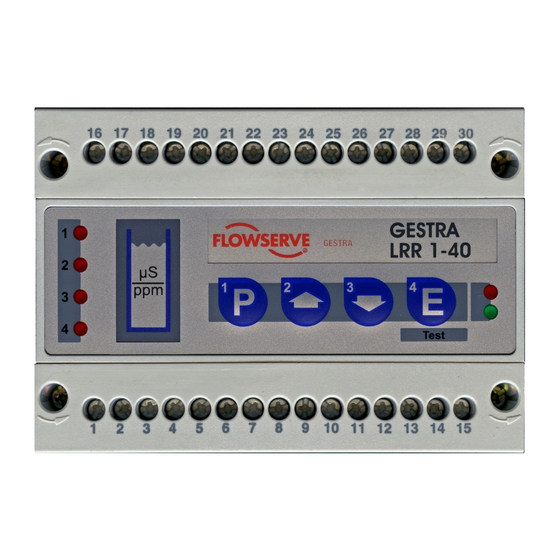
Page 12: Functional Elements
Functional Elements LRR 1-40 GESTRA LRR 1-40 µS Test Fig. 4 16 17 18 19 20 21 22 23 24 25 26 28 29 30 GESTRA LRR 1-40 µS Test 2 3 4 5 6 7 8 9 0 Fig. 5... -
Page 13: Key
Design / Functional Elements - continued - Status LED Alarm Malfunction LED 1 MAX alarm Malfunction message LED 2 Continuous blowdown valve CLOSED Malfunction message LED 3 Continuous blowdown valve OPEN Malfunction message LED 4 MIN alarm / continuous blowdown Malfunction message LED Bus status LED Power... -
Page 14: Installation
Installation LRR 1-40 Mounting on supporting rail 1. Clip control unit onto the supporting rail. Supporting rail TS 35 x 15, DIN EN 50022. 2. Align control unit. Fig. 7 Tools Screwdriver, size 5.5/100 ... - Page 15 Installation - continued - Example of Installation 17 18 19 20 21 22 23 24 GESTRA LRR 1-40 µS Test 11 12 Fig. 6 17 18 19 20 21 22 23 24 GESTRA LRR 1-40 µS Test 11 12 Fig. 7...
-
Page 16: Electrical Connection
Installation - continued - Terminal strips Screws for terminal strip " Case § Supporting rail TS 35 x 15 DIN EN 50022 Electrical Connection Control cable NRS, NRR, LRR, TRS, URB 1 To wire the equipment, multi-core twisted-pair control cable must be used for the bus line, e. - Page 17 If a safety power supply unit (e. g. SITOP smart, 24 V, 2.5 A) is used for the voltage supply of the CAN bus do not tap the supply voltage from the terminals 1 and 5 of the GESTRA control devices.
- Page 18 Electrical Connection - continued - Wiring diagram LRR 1-40 & CLOSED OPEN 17 18 19 20 21 22 23 24 GESTRA LRR 1-40 µS Test 11 12 18-36 V DC 120 Ω CAN bus Fig. 6 2.5 V DC with potentiometer...
- Page 19 Electrical Connection - continued - Wiring diagram for the sensor plug-in connectings Fig. 9 i h a Fig. 10 Fig. 11 RES 1 RES 2 Mains supply Continuous blowdown valve MAX limit, safety circuit Pin 1: Screen & Pin 2: Voltage supply 24 V DC+ (red) Continuous blowdown valve CLOSED / OPEN Pin 3: Voltage supply 24 V DC–...
- Page 20 Electrical Connection - continued - CAN bus wiring diagram URB 2 NRS, NRR, LRR, NRG, LRG, TRS, URB 1 EF, URZ RES 2 RES 1 Fig. 12 Attention Wire equipment in series. Star-type wiring is not permitted! Make sure that the bus line is separated from mains and signal lines. ...
-
Page 21: Bus Cable
The CAN address (node ID) can be set between 1 - 99. The control unit LRR 1-40 has already been configured at our works for operation with other GESTRA components and can be used straight away without having to set the node ID. - Page 22 X – 2 X – 1 X + 1 X + 2 Factory setting Automatic continous blowdown control EF 1-40 Reserved LRR 1-40 LRG 1-4... Reserved X – 2 X – 1 X + 1 X + 2 Factory setting...
-
Page 23: Node Id:
Basic Settings - continued - Factory setting The control unit LRR 1-40 features the following factory set default values: Control parameters Setpoint W: 5000 μS/cm Switching hysteresis of controller output (configuration as 2-position controller): 10 % Operating position of continuous blowdown valve: 8 % ... -
Page 24: Node Id
Basic Settings - continued - Code switch settings 2 3 4 5 6 7 8 9 0 2 3 4 5 6 7 8 9 0 Node ID Node ID Fig. 15 (Factory setting) Fig. 16 (Example 1) S 10 Baud rate Cable length 250 kBit/s... -
Page 25: Commissioning
LRG, the control unit LRR and the actuator EF. Please observe the operating instructions of the operating unit URB / SPECTORcontrol. The control unit LRR 1-40 automatically detects the type of the connected conductivity electrode. Start Apply mains voltage. -
Page 26: Operation
Operation Normal operation LED “Power” is illuminated. GESTRA LRR 1-40 LEDs 1-4 not illuminated µS Test Continuous boiler blowdown LED 2 is flashing while the continuous blowdown GESTRA LRR 1-40 valve is closing. µS LED 3 is flashing while the valve is opening. -
Page 27: Stand-By Operation
(if activated) can be de-activated during stand-by operation or when the firing is switched off. An external control command (see wiring diagram) triggers off the signal. GESTRA LRR 1-40 The continuous blowdown valve is motored into the µS CLOSED position. -
Page 28: Max Limit / Min Limit
Relay contact 4 (feedback LED 4) works as switching output for MIN limit LED 1 lights up once the set MAX limit is reached. GESTRA Relay contact 1 opens (safety circuit). LRR 1-40 µS LED 1 goes out once the value falls below its limit. Relay contact 1 closed. Test LED 4 lights up once the set MIN limit is reached. -
Page 29: Performance Test
When using the equipment as conductivity limiter please note: Note The control unit LRR 1-40 does not lock automatically when the adjusted MAX limit is exceeded If a lock function is required by the installation it must be provided in the follow-up... -
Page 30: Performance Test For Relays 1 And 4
- continued - Performance test for relays 1 and 4 Press button briefly. GESTRA LRR 1-40 LED 1 and 4 are flashing rapidly. µS LED 4 is illuminated during intermittent boiler blowdown. The test mode remains active for 10 seconds. - Page 31 Malfunctions Fault finding list for troubleshooting Equipment does not work - no function Fault: LED “Power” is not illuminated. Remedy: Apply mains voltage and wire equipment in accordance with wiring diagram. Equipment does not work correctly Fault: Due to dirt deposits on the measuring surface(s) the indicated actual value may be wrong (determined with reference measurement).
-
Page 32: System Malfunctions
System Malfunctions Danger The terminal strips of the equipment are live during operation. This presents the risk of severe cases of electric shock! Cut off power supply to the equipment before mounting or removing the terminal strips! Causes Malfunctions occur if CAN bus components have been mounted, wired or configured incorrectly or if electronic component parts are defective, or in the event of excessive heat in the equipment or electrical interference in the supply system. -
Page 33: Systematic Malfunction Analysis
System malfunctions - continued - Systematic malfunction analysis The sources of malfunctions occuring in CAN bus systems operating with several bus-based stations must be analysed systematically since faulty components or incorrect settings can give rise to negative interactions with intact bus devices in the CAN bus system. These unwanted interactions can cause error messages in fully functional bus devices, which will make fault detection even more difficult. - Page 34 System malfunctions - continued - Error message 1 LEDs 1 to 3 (4 for MIN limit) are flashing GESTRA rapidly LRR 1-40 µS A communication error has been detected. Test Fault: The initialising phase has not been finished during start-up.
- Page 35 System malfunctions - continued - Error message 3 LED bus status is flashing slowly GESTRA LRR 1-40 µS Test Fault: The data transfer between the control unit and the electrode is interrupted! Remedy: The wiring of the bus lines must be in accordance with the wiring diagram (observe polarity).
-
Page 36: Replacing Control Unit
3. When ordering spare parts please state the serial number indicated on the name plate. 4. Write down the parameters set in the operating panel URB / SPECTORcontrol and enter them in the new control unit LRR 1-40 after installation. Disposal Dismantle the equipment and separate the waste materials, using the material specification as a reference. -
Page 37: Annex
For details on the conformity of our equipment according to the European Directives see our Declaration of Conformity or our Declaration of Manufacturer. The current Declaration of Conformity / Declaration of Manufacturer are available in the Internet under www.gestra.en/documents or can be requested from us. - Page 38 For your notes...
- Page 39 For your notes...
- Page 40 Agencies all over the world: www.gestra.de GESTRA AG Münchener Straße 77 28215 Bremen Germany Telefon +49 421 3503-0 Telefax +49 421 3503-393 E-mail info@de.gestra.com www.gestra.de 818527-03/07-2017cm (808544-03) · GESTRA AG · Bremen · Printed in Germany...
Need help?
Do you have a question about the LRR 1-40 and is the answer not in the manual?
Questions and answers