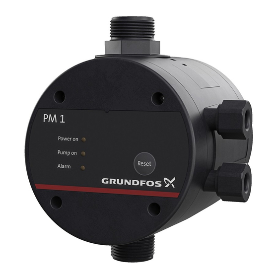
Grundfos PM 1 Service Manual
Hide thumbs
Also See for PM 1:
- User manual ,
- Installation and operating instructions manual (40 pages) ,
- Instructions manual (32 pages)
Table of Contents
Advertisement
Advertisement
Table of Contents

Summary of Contents for Grundfos PM 1
- Page 1 GRUNDFOS INSTRUCTIONS PM 1, PM 2 Service instructions...
-
Page 2: Table Of Contents
Dismantling and assembly ....................4 General description...........................4 PM 1 ..............................4 PM 2 ..............................5 Control panels ......................... 10 Control panel on PM 1 ........................10 Control panel on PM 2 ........................11 Fault finding ........................13 PM 1 ...............................13 PM 2 ...............................14 Drawings .......................... 16 Exploded view, PM 1 ........................16... -
Page 3: Symbols Used In This Document
2. Torques and lubricants See chapter for position numbers. 7. Drawings Pos. Designation Quantity Dimension Torque [Nm] Lubricant Screw, PM 1 D3.5x20 1.3 - 1.5 – Screw, PM 2 D3.5x35 1.3 - 1.5 Screw, PM 1 D4.7x40 2.8 - 3 –... -
Page 4: Dismantling And Assembly
Lubricate and tighten screws and nuts to the correct torque. See section 2. Torques and lubricants. 4.2 PM 1 4.2.1 Removing the supply cables 1. Remove screws (pos. 1), and take off front cover (pos. 2). 2. Remove terminal board cover (pos. 3). -
Page 5: Press Valve (Pos. 6) Home In The Housing (Pos
4.2.3 Removing the valve 1. Remove side cover (pos. 8) and clamp (pos. 7). 2. Remove the fitting and valve (pos. 6) out of the housing (pos. 5) by pulling the outlet fitting. Check that the valve seat is intact. Note 4.2.4 Fitting the valve 1. - Page 6 Removing the plug for sensor Fig. 4 7. Remove the complete electronic unit (pos. 4). Removing the electronic unit Fig. 5 4.3.2 Fitting the electronic unit 1. Fit the complete electronic unit (pos. 4). Ensure that the sensor cable is laid up to the control unit so that it can reach the plugs and Note does not get pinched.
- Page 7 Fitting the plug for sensor Fig. 6 3. Lead cables (pos. 9 and 10) into the cable entries (pos. 11), and tighten them. 1x115/230 V 50/60 Hz, PE 1x230 V 50/60 Hz, PE Connecting cables to single- and three-phase motors Fig.
- Page 8 4.3.3 Removing the pressure sensor 1. Follow the instructions in section 4.3.1 Removing the electronic unit. 2. Remove plug for sensor (pos. 13). 3. Note how the sensor is positioned. Correct fitting of sensor Fig. 9 4. Unscrew pressure sensor (pos. 12) counter-clockwise until it is free. 4.3.4 Fitting the pressure sensor 1.
- Page 9 4.3.5 Removing the diaphragm 1. Slacken screws (pos. 16), and remove cover for diaphragm (pos. 15). 2. Remove diaphragm (pos. 14). 4.3.6 Fitting the diaphragm 1. Fit diaphragm (pos. 14) in the cover for diaphragm (pos. 15). The diaphragm must not be lubricated. Note 2.
-
Page 10: Control Panels
5. Control panels 5.1 Control panel on PM 1 Fig. 13 Control panel Pos. Description Function The green indicator light is permanently on "Power on" when the power supply has been switched on. The green indicator light is permanently on "Pump on"... -
Page 11: Control Panel On Pm 2
5.2 Control panel on PM 2 Fig. 14 Control panel Pos. Description Function The pressure scale has 13 light fields "Pressure indicating the pressure from 0 to 6 bar. scale" All light fields illuminate briefly when the power supply is switched on. The green indicator light is permanently on when the pump is running. - Page 12 DIP switch Description Default setting Name Start pressure (p start With these DIP switches the start pressure can be set from 1.5 to 5.0 bar in steps of 0.5 bar. Example: All set to OFF START DIP switch 1 = "ON" = 1.5 bar) start DIP switch 2 = "ON"...
-
Page 13: Fault Finding
Check and repair the pipework. b) Leaky non-return valve. Clean or replace the non-return valve. c) A valve close to the PM 1 outlet has been Open the valve. closed. 5. The pump does not stop. a) The pump cannot deliver the necessary Replace the pump. - Page 14 6.2 PM 2 Warning Before starting work on the pump/PM unit, make sure that the power supply has been switched off and that it cannot be accidentally switched on. Fault Cause Remedy 1. The green light field for "0 bar" a) The fuses in the electric installation have blown.
- Page 15 Fault Cause Remedy 11. The red "Alarm" indicator light a) Too many start/stop sequences within a short period. Check the tank precharge pressure, and flashes three times per period, The pressure tank has no precharge pressure, or the tank recharge the tank, if necessary. and each pump start is delayed size is insufficient.
-
Page 16: Drawings
7. Drawings 7.1 Exploded view, PM 1 Fig. 16 Exploded view, PM 1 7.2 Exploded view, PM 2 Fig. 17 Exploded view, PM 2 Subject to alterations. 16 / 17... - Page 17 Unit 1, Ground floor Turkey Phone: +387 33 713 290 Siu Wai Industrial Centre Norway GRUNDFOS POMPA San. ve Tic. Ltd. Sti. Telefax: +387 33 659 079 29-33 Wing Hong Street & GRUNDFOS Pumper A/S Gebze Organize Sanayi Bölgesi e-mail: grundfos@bih.net.ba 68 King Lam Street, Cheung Sha Wan Strømsveien 344...


Need help?
Do you have a question about the PM 1 and is the answer not in the manual?
Questions and answers