Carrier 48LC 04 Controls, Start-Up, Operation And Troubleshooting
Single package rooftop units with comfortlink controls version 1.x and puron (r-410a) refrigerant
Hide thumbs
Also See for 48LC 04:
- Installation instructions manual (48 pages) ,
- Controls, start-up, operation and troubleshooting (164 pages) ,
- Service and maintenance instructions (76 pages)
Table of Contents
Advertisement
Quick Links
48/50LC 04---06
Single Package Rooftop Units
with ComfortLink Controls Version 1.X
and PURONr (R---410A) Refrigerant
IMPORTANT: This literature covers 48/50LC 04- -06 models with
ComfortLink Software version 1.x.
TABLE OF CONTENTS
. . . . . . . . . . . . . . . . . . . . . . . . . . . . . . . . . . . . . . . . .
. . . . . . . . . . . . . . . . . . . . . . . . . . . . . . . .
. . . . . . . . . . . . . . . . . . . . . . . . . . . . . . . . . .
. . . . . . . . . . . . . . . . . . . . . . . . . . . . . . . . . . . . . . . . .
. . . . . . . . . . . . . . . . . . . . . . . . . . . . .
. . . . . . . . . . . . . . . . . . . . . . . . . . . . . . . . . . . . . . . . .
. . . . . . . . . . . . . . . . . . . . . . . . . . . . . . . . . . . .
. . . . . . . . . . . . . . . . . . . . . . . . . . . . . . .
. . . . . . . . . . . . . . . . . . . . . . . . . . . . .
. . . . . . . . . . . . . . . . . . . . . . . . . . . . . . . . . . .
. . . . . . . . . . . . . . . . . . . . . . . . . . . . . . . .
. . . . . . . . . . . . . . . . . . . . . . . . . . . . . . . . . . . . .
. . . . . . . . . . . . . . . . . . . . . . . . . . . . . . . . . . . . .
. . . . . . . . . . . . . . . . . . . . . . . . . . . . . . . . . . . .
. . . . . . . . . . . . . . . . . . . . . . . . . . . . . . . . . .
. . . . . . . . . . . . . . . . . . . . . . . . . . . .
. . . . . . . . . . . . . . . . . . . . . . . . . . . . . . .
. . . . . . . . . . . . . . . . . . . . . . . . . . . . . .
. . . . . . . . . . . . . . . . . . . . . . . . . . . . . . . . . . .
. . . . . . . . . . . . . . . . . . . . . . . . . . . . . . . . .
. . . . . . . . . . . . . . . . . . . . . . . . . . . . .
. . . . . . . . . . . . . . . . . . . . . . . . . . . . . . .
. . . . . . . . . . . . . . . . . . . . . . . . . . . . . . . .
. . . . . . . . . . . . . . . . . . . . . . . . . . . .
Controls, Start---Up, Operation
and Troubleshooting
. . . . . . . . . . . . . . . . . . . . . . . . .
. . . . . . . . . . . . . . . . . . . . . . . . . . .
. . . . . . . . . . . . . . . . . . . . . . . . . .
. . . . . . . . . . . . . . . . .
. . . . . . . . . . . . . . . . . . . . . .
. . . . . . . . . . . . . . . . . . . . . . . . . . .
. . . . . . . . . . . . . . . . . . . . . . . . .
. . . . . . . . . . . . . . . . .
. . . . . . . . . . . . . . . . . . . .
. . . . . . . . . . .
. . . . . . . . . . . . . . . . . . . . . . . . . . . . . . . . . . . . . . .
Page
2
. . . . . . . . . . . . . . . . . . . . . . . . . . . . . . . . . . . .
3
3
. . . . . . . . . . . . . . . . . . . . . . . . . . . . . . . . . . . . . . . . .
3
. . . . . . . . . . . . . . . . . . . . . . . . . . . . . . . . . . . . .
3
. . . . . . . . . . . . . . . . . . . . . . . . . . . . . . . . . . . . . .
4
4
4
4
6
. . . . . . . . . . . . . . . . . . . . . . . . . . . . . . . . . . . .
6
. . . . . . . . . . . . . . . . . . . . . . . . . . . . . . . . . . . . .
6
6
6
6
6
. . . . . . . . . . . . . . . . . . . . . . . . . . . . . . . . . . . . . . . . . .
6
6
6
7
7
7
7
. . . . . . . . . . . . . . . . . . . . . . . . . . . . . . . . . . . . . .
7
8
8
8
8
. . . . . . . . . . . . . . . . . . . . . . . . . . . . . . . . . . . .
. . . . . . . . . . . . . . . . . . . . . . . . . . . . . . . . . . . . . . . . .
8
8
8
8
8
9
. . . . . . . . . . . . . . . . . . . . . .
. . . . . . . . . . . . . . . . . . . . . . . . . . . . . . .
. . . . . . . . . . . . . . . . . . . . .
. . . . . . . . . . . . . . . . . . . . . . . . . . . . . . .
. . . . . . . . . . . . . . . . . . . . . . . . . .
. . . . . . . . . . . . . . . . . . . . . . . . . . . .
. . . . . . . . . . . . . . . . . . . . . . . . . . .
. . . . . . . . . . . . . . . . . . . . . . . . . . . . . . . .
. . . . . . . . . . . . . . . . . . . . . . . . .
. . . . . . . . . . . . . . . . . . . . . . . . . . .
. . . . . . . . . . . . . . . . . . . . . . . . . . . . . .
. . . . . . . . . . . . . . . . . . . . . . . . . . . . . . . . .
. . . . . . . . . . . . . . . . . . . . . . . . . . . . . . . . .
. . . . . . . . . . . . . . . . . . .
. . . . . . . . . . . . . . . . . . . . . . . . . . .
. . . . . . . . . . . . . . . . . . . . . . . . . . . . . . .
. . . . . . . . . . . . . . . . . . . . . . . . . . . . . . . . .
. . . . . . . . . . . . . . . . . . . . . . . . . . . . . . . . .
. . . . . . . . . . . . . . . . . . . . . . . . . . . .
. . . . . . . . . . . . . . . . . . . . . . .
. . . . . . . . . . . . . . . . . . . . . . . . . . . . . . . . . . .
. . . . . . . . . . . . . . . . . . . . . . . . . . . . . .
. . . . . . . . . . . . . . . . . . . . . . . . . . . .
. . . . . . . . . . . . . . . . . . . . . . . . . . . . . . . . . .
. . . . . . . . . . . . . . . . . . . . . . . . . . . . . . . . .
. . . . . . . . . . . . . . . . . . . . . .
9
9
9
9
11
11
11
11
11
11
11
11
12
12
12
12
12
12
12
13
13
14
14
14
15
18
19
. . . . . . .
22
23
25
. . . . . . . . .
25
26
26
26
27
27
27
27
32
Advertisement
Table of Contents
Troubleshooting

Subscribe to Our Youtube Channel
Related Manuals for Carrier 48LC 04


Summary of Contents for Carrier 48LC 04
-
Page 1: Table Of Contents
..... . . Control Set Point and Confirmation Log ....Carrier Comfort Network (CCN) Configuration .. -
Page 2: Safety Considerations
..... . . which could result in personal injury or death. CAUTION is used to identify unsafe practices which may result in minor personal Carrier Comfort Network (CCN) Interface ... . . -
Page 3: General
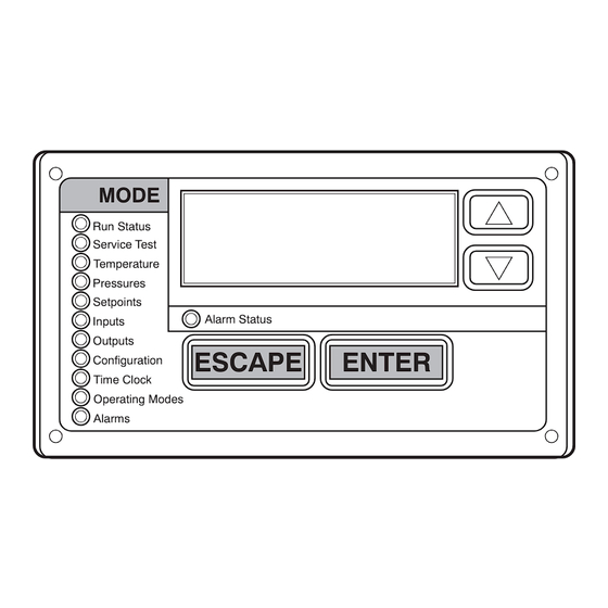
The control system is easy to access, configure, diagnose S Outputs and troubleshoot. S Configuration The ComfortLink control is fully communicating and cable-ready S Timeclock for connection to the Carrier Comfort Network (CCN) building S Operating Modes management system. control provides high-speed communications for remote monitoring via the Internet. -
Page 4: Accessory Navigator Display
3V zoning system, linkage compatible air source, lines of display and the Scrolling Marquee has a single line. All universal controller, and all other devices operating on the Carrier further discussions and examples in this document will be based on communicating network. - Page 5 Table 2 – Scrolling Marquee Mode and Menu Display Structure SERVICE TIME OPERATING TEMPERATURES PRESSURES SETPOINTS INPUTS OUTPUTS CONFIGURATION ALARMS STATUS TEST CLOCK MODES Time of Auto View Service Test Thermostat Display Control Reset All Configuration Mode Temperatures Inputs Outputs Modes Current (DISP)
-
Page 6: Conventions Used In This Manual
Conventions Used in This Manual On 3-phase units, it is important to be certain the compressors are rotating in the proper direction. To determine whether or not The following conventions for discussing configuration points for compressors are rotating in the proper direction, use a the local display (Scrolling Marquee or Navigator... -
Page 7: Condenser Fans And Motors
Position Test (Service Test INDP ECON) to 0 (Economizer Damper Closed) and elevation. Purchase these orifices from your local Carrier dealer. Indoor Fan Speed Test (Service Test FANS F.SPD) equal to Follow instructions in accessory Installation Instructions to install ... -
Page 8: Gas Heat (48Lc)
Gas Heat (48LC) Thermostat Control Inspect the gas heat section of the unit. Verify the number of Wire accessory thermostat to the corresponding R, Y1, Y2, W1, W2, and G terminals on the field connection terminal board located burners match the number of heat exchanger openings and the at the unit control box. -
Page 9: Space Humidistat Control
IAQ Switch item. thermostat control type configuration, ConfigurationUNITT.CTL, selects the unit response to the If an IAQ Switch accessory was field installed, the unit must be thermostat inputs above. See below for Space Humidity Switch. configured for it by setting ConfigurationAIR.QII.CF, Space Humidistat Control identifies the normally open or normally closed status of this input when the indoor air quality value is low (good) and also selects the... - Page 10 4. Configure the beginning of the occupied time period for the correct value for hours, in 24- -hour (military) time. Press Period 1 (OCC). Press ENTER to go into Edit mode, and ENTER and hour value is saved and the minutes digits will the first two digits of the 00.00 will start flashing.
-
Page 11: Service Test
SERVICE TEST Table 4 – Service Test Modes and Submodes Directory The Service Test function can be used to verify proper operation of DISPLAY MENU/ . SUB--- MENU/ . . EXPANDED NAME VALUES compressors, heating stages, indoor fan, power exhaust fans, NAME economizer, and the alarm relay. -
Page 12: Remote Occupancy
Remote Occupancy configuration changes. General unit configurations are also covered under this Unit Configuration menu. The remote occupancy input is provided on the field connection Start- - Up Delay (S.DLY) terminal board (TB). Remote Occupancy Switch configuration, ConfigurationUNITRM.SW, identifies the This configuration sets the control start-up delay after the power is normally open or normally closed status of this input when interrupted. -
Page 13: Modes
Temperature Compensated Start Cooling Factor HVAC Operation Disabled (HV.DN) (TCS.C) Allow disabling of HVAC mode. This is only available on a network connection and shows if the unit has been forced into the This factor is used in the equation of the Temperature Compensated disabled status. -
Page 14: Temperature Setpoint Determination
Temperature Setpoint Determination (INPUTSGEN.IRM.OC) point will show the status of the switch. Setpoints are used to control the unit while under space temperature sensor control. The Cool Setpoint in Effect (EFF.C) STATE OF SWITCH SWITCH and the Heat Setpoint in Effect (EFF.H) are the points in which the TYPE OF SWITCH AND STATE OF CONFIGURATION... -
Page 15: Cooling Operation
control if the System Mode (SYS) status is enabled. The fan will Refer to the speed configurations below for an overview of usage; remain on if compressors or heat relays are ever stuck on. If refer to other specific operating sequences for more details on fan configured for fan status switch (FN.SW) and Shut Down on IDF operation during the corresponding mode. - Page 16 Free Cooling, and Dehumidification. These are all part of a general T.CTL = 1 or 2 (1 Stage Y1 or 2 stage Y1) cooling mode and resemble the specific type of cooling that being Stage timers, Supply air trend, and supply air temperature limits do performed at any given time.
- Page 17 specific unit wiring diagram and or service manual for details on to wire to MBB J9-5 and 6. The RH sensor input requires the ECB how the outdoor fan operates. In general, the outdoor fan will be to be installed if not already. on full speed when the compressor is turned on.
-
Page 18: Heating Operation
(CCSP). If running FS.MX for one minute and the SAT is still On belt drive VFD fan units the fan will always run at Supply Fan lower than the comfort setting, the cooling stage will be removed Maximum Speed (FS.MX) during heat mode. for 10 min before trying again. -
Page 19: Economizer
Status →HEAT →DMD.H). The control tries to anticipate the condition of the rollout switch, limit switches, the Hall Effect change in the space because of its current stage status. This sensor, as well as the flame sensor. If the unit is controlled through anticipation is based on the Heat Demand Trend (Operating a room thermostat or space sensor set for fan auto and 45 seconds Modes →HEAT →TRD.H). - Page 20 Title 24 FDD Configuration Points Furthermore, the control shall test for a mechanically disconnected actuator after T24CHDLY minutes have expired when any of the LOG.F (T24LOGFL) – “Log Title 24 Faults” – defines when Title following occur (this is to allow the heat/cool cycle to dissipate and 24 mechanically disconnected actuator faults should be logged: not influence SAT): Range=YES, NO,...
- Page 21 ET.MX (T24TSTMX) – “T24 Test Maximum Pos” – maximum or commanded position when E.CTL =2. Because the wiring has a position above which tests for a mechanically disconnected built- -in 500- -ohm resistor, the 4 to 20mA signal is converted to a 2 actuator will not be performed.
-
Page 22: Air- -Side Economizer High Limit Switches Control
The shape of the Economizer Minimum Position vs. Fan Speed Table 5 – LCSP and HCSP Transitions for curve is determined by the configuration parameters: Econ Min at Space Temperature Mode 25% Fan speed (ConfigurationECONMP.25), Econ Min at CURRENT SAT COOL DEMAND NEXT SAT 50% Fan speed (ConfigurationECONMP.50), Econ Min at... -
Page 23: Indoor Air Quality (Iaq)
UEFC = 1 (Unoccupied) Sensor Value at 4mA (ConfigurationAIR.QI.4M) and IAQ Sensor Value at 20mA (ConfigurationAIR.QI.20M). When UEFC is set to 1, unoccupied free cooling can occur IA.CF = O (No IAQ) throughout the entire unoccupied period. The space temperature must be higher than the mid- -point between the occupied cooling IA.CF = 0 signifies that there is no IAQ sensor installed. - Page 24 IA.CF = 2 (Override IAQ) override position is configured by the IAQ Override Position (ConfigurationAIR.QOVR.P). When IA.CF = 2, the IAQ algorithm maintains the damper at Econ Outdoor Air Quality (Analog Input) Min at Max Fan Speed (ConfigurationECONMP.MX) when the indoor fan speed is at Supply Fan Maximum Speed The ComfortLink control can be configured for outdoor air quality (ConfigurationI.FANFS.MX) or along the curve on Fig.
-
Page 25: Temperature Compensated Start
It is possible to configure the ComfortLink control to participate as to 4 hours. If the time is set to 0, the override function will an element of the Carrier Comfort Network (CCN) system directly become disabled. from the local display. This section will deal with explaining the Timed Override Hours (SCH.OOV.EX) -
Page 26: Demand Limit
SPT Override Enabled? (SCH.OOV.SP) fans, and heat stages. This point must also be forced, and is reset automatically when not forced, and at POR. If a space sensor is present, then it is possible to override an NOTE: HVACDOWN can be used as an immediate shutdown of unoccupied period by pushing the override button on the T55 or the unit before limiting capacity (ex. -
Page 27: Troubleshooting
CCN Alarm Broadcast Alarm Output terminals. Each alarm may also be broadcast on the CCN network. Active alarms and past alarm history can be Operators of CCN networks might not want to be notified of reviewed and cleared via the local display or a CCN device. The “striking”... - Page 28 Alert Codes T051 (with Current Sensor) Alert Code T076 - - Return Air Thermistor Failure This alert occurs when the temperature is outside the range –40_ to This alert can only be activated if Current Sensing A1 is enabled 240_F (–40_ to 116_C). This alert will only occur if the unit is (Configuration COOL CS.A1 = Enabled).
- Page 29 40_F. All the above timers will reset if the suction temperature rises Alert Code T175 – Loss of communication with VFD above SST.O for 1 minute. This alert causes a strike for the circuit. This alert occurs when the Indoor Fan Type (Configuration I.FAN If the OAT is less than 10_F, the circuit will shut down without a ...
- Page 30 switch. If the IDF is configured to shut down the unit when this automatically when Y1 and Y2 are not on simultaneously with W1 and W2. alarm occurs (ConfigurationI.FANIDF.F = YES), then this Alert Code T414 alarm can only be reset manually and the unit is shut down. If the There are10 different alerts under this one alert code.
- Page 31 S Economizer Not Economizing When It Should Alert Code T416 - - OAQ Input Out of Range In this case, the economizer should be enabled, but for some This alert occurs when the OAQ input (on ECB) is less than 3.5 mA and the sensor is configured as installed.
-
Page 32: Control Module Communication
The MBB has one yellow LED which is used to indicate CCN blinking, check the DIP switch positions on the board. If the red communication activity. The Carrier Comfort Network (CCN) LEDs are not blinking in unison, verify that correct power is being LED will blink during times of network communication. -
Page 33: Cooling Troubleshooting
Cooling Troubleshooting Use the Scrolling Marquee display or a CCN device to view the If alarms conditions are corrected and cleared, operation of the cooling status display and the cooling diagnostic display (see compressors and fans may be verified by using the Service Test Appendix A) for information on the cooling operation. -
Page 34: Economizer Troubleshooting
Economizer Troubleshooting Title 24 FDD Status Points Use the unit Scrolling Marquee display or a CCN device to view The control shall utilize the following points to determine whether the economizer status display and the economizer diagnostic a damper is mechanically disconnected: display (see Appendix A) for information on the economizer ECONO - - “Economizer Installed”... - Page 35 Close at 0% or Fully Open at 100%. return is backwards. Economizer (E.CAL) procedure. Economizer is Not at Configured Unit is operating under free cooling or a force is Economizer is operating correctly. Minimum Position applied to the commanded position. LEGEND Carrier Comfort Network Indoor Air Quality...
-
Page 36: Heating Troubleshooting
Heating Troubleshooting Gas Heat (48LC Units) See Table 10 for general gas heating service analysis. See Fig. 8 for Use the unit Scrolling Marquee display or a CCN device to view service analysis of the IGC board logic. Check the status LED on the heating status display and the heating diagnostic display (see the IGC board for any flashing alarm codes and correct any causes. - Page 37 24 VOLTS DEFECTIVE 1 FLASH - INDOOR FAN DELAY FLASHING LED is BETWEEN IGC BOARD MODIFIED (HEATING) F1 AND C 2 FLASHES - OPENING OF LIMIT SWITCH 1. BLOWN 5 AMP FUSE 3 FLASHES - FLAME SENSOR 2. DEFECTIVE 24V TRANS. INDICATES FLAME WITH 3.
- Page 38 Table 11 – IGC Board LED Alarm Codes ACTION TAKEN BY DESCRIPTION RESET METHOD PROBABLE CAUSE FLASH CONTROL CODE Normal Operation — — — Hardware Failure No gas heating. Loss of power to the IGC. Check 5 amp fuse on IGC, —...
-
Page 39: Phase Loss Protection
Phase Loss Protection The phase loss protection option will monitor the three-phase electrical system to provide phase reversal and phase loss protection. Phase Reversal Protection If the control senses an incorrect phase relationship, the relay (K1) will be de-energized (opening its contact). If the phase relationship is correct, the relay will be energized. -
Page 40: Transducer Troubleshooting
SCT.A SCT.A Size 04 Units Size 05 & 06 Units C12219 Fig. 10 - - Saturated Condensing Temperature Thermistor Location — 48/50LC04- -06 Transducer Troubleshooting forced are indicated as ‘forcible’ in the write status column of the display and CCN tables. The electronic control uses suction pressure transducers to measure If the user needs to force a variable, follow the same process as the suction pressure of the refrigerant circuits. - Page 41 Table 13 – Temperature (_F) vs Resistance/Voltage Drop Values for OAT, SAT, and SPT Thermistors (10K at 25_C Type II Resistors) TEMP RESISTANCE VOLTAGE TEMP RESISTANCE VOLTAGE TEMP VOLTAGE RESISTANCE (Ohms) DROP (V) (Ohms) DROP (V) DROP (V) (Ohms) –25 196,453 4.758 3.056...
- Page 42 Table 14 – Temperature (_F) vs. Resistance/Voltage Drop Values for SCT Sensors (5K at 25_C Resistors) TEMP RESISTANCE VOLTAGE TEMP RESISTANCE VOLTAGE TEMP VOLTAGE RESISTANCE (Ohms) DROP (V) (Ohms) DROP (V) DROP (V) (Ohms) –25 3.699 98,010 1.982 7,866 0.511 1,190 –24 3.689...
-
Page 43: Major System Components
Table 15 – Pressure (psig) vs. Voltage Drop Values for Suction Pressure Transducers PRESSURE VOLTAGE PRESSURE VOLTAGE PRESSURE VOLTAGE PRESSURE VOLTAGE (psig) DROP (V) (psig) DROP (V) (psig) DROP (V) (psig) DROP (V) 0.465 1.135 1.804 2.474 0.485 1.154 1.824 2.493 0.505 1.174... - Page 44 C12220 Fig. 11 - - 48LC 04- -06 ComfortLink Control Schematic...
- Page 45 C12221 Fig. 12 - - 50LC 04- -06 ComfortLink Control Schematic...
- Page 46 C12222 Fig. 13 - - 48LC 04- -06 ComfortLink Power Schematic - - 208/230V, 460V 3 Phase Units...
- Page 47 C12223 Fig. 14 - - 48LC 04- -06 ComfortLink Power Schematic - -575V 3 Phase Units...
- Page 48 C12224 Fig. 15 - - 50LC 04- -06 ComfortLink Power Schematic - - 208/230V, 460V, 575V 3 Phase Units...
-
Page 49: Main Base Board (Mbb)
(ECB). The MBB receives inputs from thermistors and transducers. RED LED - STATUS GREEN LED - YELLOW LED - LEN (LOCAL EQUIPMENT NETWORK) CCN (CARRIER COMFORT NETWORK) INSTANCE JUMPER (SET TO 1) CEPL130346-01 STATUS C07026 Fig. 16 - - Main Base Board (MBB) - Page 50 HT.2 Heat Stage 1 relay relay J10, 27 COMMUNICATION Local Equipment Network (LEN) communication J5, 1--- 3 Carrier Comfort Network (CCN) communication J5, 5--- 7 Network device power 24 VAC J5, 9--- 10 Scrolling Marquee Display (LEN) communication J4, 1--- 3...
-
Page 51: Economizer Control Board (Ecb)
Economizer Control Board (ECB) By digitally communicating with the ECB, the economizer actuator is able to provide the damper position and diagnostic The ECB controls the economizer actuator. (See Fig. 17 and Table information the ComfortLink controller. The damper 17.) The control signal from the ECB uses either the MFT position is displayed at OutputsECONEC.AP. - Page 52 Power exhaust 2 relay relay J8, 6 EC.CP Commanded Economizer position 0--- 20 mA J9, 1 COMMUNICATION Local Equipment Network (LEN) communication J2, 1--- 3 Carrier Comfort Network (CCN) communication EC.CP & Economizer actuator position MFT communication J7, 1 EC.AP (digital control)
-
Page 53: Integrated Gas Control (Igc) Board
Integrated Gas Control (IGC) Board The IGC is provided on gas heat units. (See Fig. 18 and Table 18.) The IGC controls the direct spark ignition system and monitors the rollout switch, limit switch, and induced-draft motor Hall Effect switch. RED LED-STATUS C07028 Fig. -
Page 54: Low Voltage Terminal Board
This circuit board provides a field connection point for unit communications. The Local Equipment Network (LEN) RJ- -11 connector allows a handheld Navigator to be plugged in to access the unit’s menus. The Carrier Comfort Network (CCN) RJ- -11 connector or the CCN screw terminals allow building communication connections. - Page 55 Table 20 – Central Terminal Board (CTB) Connections CONNECTION LA- PIN NUMBER POINT DESCRIPTION 24Vac FROM 24Vac TO Cool 1 Call ECON Cool 2 Call ECON Heat Stage 1 Call CONTL BOARD T’STAT Heat Stage 2 Call CONTL BOARD IGC Fan Input CONTL BOARD Cool 1 Call jumper DDC T’STAT...
-
Page 56: Variable Frequency Drive (Vfd)
Failure to follow this caution may result in damage to the unit or in degradation of unit performance. Do not run the Carrier Assistant through the VFD keypad. TERMINALS This will cause parameters to change value that are not desired 28 –... - Page 57 Table 22 – VFD Parameters Configured by Factory or VFD Keypad Parameter Group Parameter Title ABB Parameter HVAC Default CARRIER Options COMM PROT SEL 9802 NOT SEL LEN (6) EFB PROTOCOL ID 5301 0000 hex 0601 hex EFB STATION ID...
-
Page 58: Vfd Diagnostics (With Keypad)
Table 26 – VFD Motor Default Configurations UNIT UNIT COMFORTLINK CCN POINT (DISPLAY MENU ITEM) UNIT SIZE STATIC VOLTAGE VFD1NVLT VFD1NAMP VFD1NFRQ VFD1NRPM VFD1NPWR VFD1MAXA (Digits OPTION (Digit 12) (N.VLT) (N.AMP) (N.FRQ) (N.RPM) (N.PWR) (MAX.A) 7 & 8) (Digit 10)* Medium (2) 1725 208/230v... - Page 59 3015 UNDERLOAD CURVE. THERM FAIL Internal fault. The thermistor measuring the internal temperature of the drive is open or shorted. Contact Carrier. Internal fault. A communication ---related problem has been detected between the OMIO and OINT boards. Contact OPEX LINK Carrier.
- Page 60 FAULT NAME IN PANEL DESCRIPTION AND RECOMMENDED CORRECTIVE ACTION CODE 101--- 105 SYSTEM ERROR Error internal to the drive. Contact Carrier and report the error number. 201--- 206 SYSTEM ERROR Error internal to the drive. Contact Carrier and report the error number. 1000 Parameter values are inconsistent.
-
Page 61: Scrolling Marquee Display
* This alarm is not indicated by a relay output, even when the relay output is configured to indicate alarm conditions, parameter 1401 RELAY OUTPUT = 5 (ALARM) or 16 (FLT/ALARM). Scrolling Marquee Display Carrier Comfort Network (CCN) Interface This device is the keypad interface used to access rooftop The units can be connected to the CCN if desired. - Page 62 COM terminal, and the black wire to the (–) terminal. 4. The RJ14 CCN connector on CIB can also be used, but is only intended for temporary connection (for example, a laptop computer running Carrier network software). 5. Restore power to unit. CCN BUS...
-
Page 63: Protective Devices
Protective Devices ComfortLink does not directly read this. The relay switch is a normally open device that closes when power is applied; this Compressor Protection allows the compressor to be energized without problem. If the Overcurrent sensor detects high water levels for 10 seconds straight, it will open the contact breaking the compressor call. - Page 64 TB1-T55 TO MAIN BASE BOARD SENSOR 1 SENSOR 2 SENSOR 3 SENSOR 4 SPACE TEMPERATURE AVERAGING --4 T-55 SENSOR APPLICATION TB1-T55 TO MAIN BASE BOARD SENSOR 1 SENSOR 3 SENSOR 2 LEGEND -- Terminal Block ______ -- Factory Wiring _ _ _ _ -- Field Wiring SENSOR 4 SENSOR 5...
- Page 65 4- -20mA Input A SAT sensor in the supply duct is the preferred configuration for TB or TB B- -COM Sensor Common systems with Carrier variable volume and temperature (VVT) TB or TB B- -R- -2 24vac Output accessory controls.
-
Page 66: Ccn Tables
APPENDIX — LOCAL DISPLAY AND CCN TABLES MODE — RUN STATUS CCN TABLE/ CCN WRITE ITEM EXPANSION RANGE UNITS CCN POINT Sub--- TABLE STATUS RUN STATUS STATUS DISPLAY VIEW Auto View of Run Status (VIEW = Display only) HVAC HVAC Mode Status 1=Disabled 2=Ventilation HVACMODE... - Page 67 APPENDIX — LOCAL DISPLAY AND CCN TABLES MODE — RUN STATUS (cont) CCN TABLE/ CCN WRITE ITEM EXPANSION RANGE UNITS CCN POINT Sub--- TABLE STATUS S.VFD SUPPLY FAN VFD VFD_DATA VFD1 Status Word 1 NNNNN VFD1STAT VFD1 Actual Speed % NNN.n VFD1_SPD VFD1 Actual Motor RPM...
- Page 68 APPENDIX — LOCAL DISPLAY AND CCN TABLES MODE — RUN STATUS (cont) CCN TABLE/ CCN WRITE ITEM EXPANSION RANGE UNITS CCN POINT Sub--- TABLE STATUS (GENERIC = CCN only) GENERIC up to 20 points (LON_DATA = CCN only) LON_DATA nviSpaceTemp xxx.x °...
- Page 69 APPENDIX — LOCAL DISPLAY AND CCN TABLES MODE — SERVICE TEST ITEM EXPANSION RANGE UNITS CCN TABLE/Sub--- TABLE CCN POINT SERVICE TEST TEST Field Service Test Mode Off/On (TEST = display only) INDP Test Independent Outputs TESTINDP ECON Economizer Position Test 0 to 100 S_ECONO E.CAL...
- Page 70 APPENDIX — LOCAL DISPLAY AND CCN TABLES MODE — INPUTS CCN TABLE/ CCN WRITE DISPLAY WRITE ITEM EXPANSION RANGE UNITS CCN POINT Sub--- TABLE STATUS STATUS INPUTS STATUS DISPLAY STAT Thermostat Inputs UINPUT Thermostat Y1 Input Off/On forcible forcible Thermostat Y2 Input Off/On forcible forcible...
- Page 71 APPENDIX — LOCAL DISPLAY AND CCN TABLES MODE — CONFIGURATIONS CCN TABLE/ PAGE ITEM EXPANSION RANGE UNITS DEFAULT CCN POINT Sub--- TABLE CONFIGURATION SERVICE CONFIGURATION DISP Display Configuration DISPLAY METR Metric Display Off/On DISPUNIT LANG Language Selection 0=English LANGUAGE 1=Spanish 2=French 3=Portuguese PROT...
- Page 72 APPENDIX — LOCAL DISPLAY AND CCN TABLES MODE — CONFIGURATION (cont) CCN TABLE/ PAGE ITEM EXPANSION RANGE UNITS DEFAULT CCN POINT Sub--- TABLE COOL Cooling Configuration COOL_CFG N.STG Number of Stages 1 to 2 NUM_STAG MRT.C Compressor Min On Time 120 to 999 MIN_ON MOT.C...
- Page 73 APPENDIX — LOCAL DISPLAY AND CCN TABLES MODE — CONFIGURATION (cont) CCN TABLE/ PAGE ITEM EXPANSION RANGE UNITS DEFAULT CCN POINT Sub--- TABLE ECON (cont) Economizer Configuration ECON_CFG MP .50 Econ Min at 50% Fanspeed 0 to 100 MINP_50 MP .75 Econ Min at 75% Fanspeed 0 to 100 MINP_75...
- Page 74 APPENDIX — LOCAL DISPLAY AND CCN TABLES MODE — CONFIGURATION (cont) CCN TABLE/ PAGE ITEM EXPANSION RANGE UNITS DEFAULT CCN POINT Sub--- TABLE ALM.O Alarm Relay Config. ALM_CFG A.SPC SPT/SPRH Sensor Failure No/Yes SPACE_AL A.SRT SAT/RAT Sensor Failure No/Yes SATRATAL A.OAT OAT Thermistor Failure No/Yes...
- Page 75 APPENDIX — LOCAL DISPLAY AND CCN TABLES MODE — CONFIGURATION (cont) CCN TABLE/ PAGE ITEM EXPANSION RANGE UNITS DEFAULT CCN POINT Sub--- TABLE SCH.O CCN Schedule Overrides SCHEDOVR SCH.N Schedule Number 0 = Always Occupied SCHEDNUM 1---64 = Local Schedule 65---99 = Global Schedule HOL.G Accept Global Holidays...
- Page 76 APPENDIX — LOCAL DISPLAY AND CCN TABLES MODE — TIME CLOCK CCN TABLE/ ITEM EXPANSION RANGE UNITS DEFAULT CCN POINT Sub--- TABLE TIME CLOCK CONFIGURATION TIME Time of Day TIME TIME Hour and Minute xx.xx hh.mm TIME DATE Current Date MNTH Month of Year January, February, ...,...
- Page 77 APPENDIX — LOCAL DISPLAY AND CCN TABLES MODE — OPERATING MODES DISPLAY CCN TABLE/ ITEM EXPANSION RANGE UNITS CCN POINT WRITE WRITE Sub--- TABLE STATUS STATUS OPERATING MODES MAINTENANCE DISPLAY MODE Control Modes MODES Unit operation disabled SYS_MODE_TEXT1 Unit operation enabled SYS_MODE_TEXT2 Service test enabled (table only)
- Page 78 APPENDIX — LOCAL DISPLAY AND CCN TABLES MODE — OPERATING MODES (cont) DISPLAY CCN TABLE/ ITEM EXPANSION RANGE UNITS CCN POINT WRITE WRITE Sub--- TABLE STATUS STATUS HEAT HEATDIAG Heat Mode Diagnostic HEAT In Heating Mode? No/Yes IN_HEAT OK.HT OK to Select Heat Mode? No/Yes OKTOHEAT MS.TG...
- Page 79 APPENDIX — LOCAL DISPLAY AND CCN TABLES MODE — OPERATING MODES (cont) DISPLAY CCN TABLE/ ITEM EXPANSION RANGE UNITS CCN POINT WRITE WRITE Sub--- TABLE STATUS STATUS LINKDATA (LINKDATA = CCN only) CCN --- Linkage Supervisory Element # SUPE--- ADR Supervisory Bus SUPE--- BUS Supervisory Block Number...
-
Page 80: Control Set Point And Configuration Log
CONTROL SET POINT AND CONFIGURATION LOG MODEL NO.: SOFTWARE VERSIONS SERIAL NO.: MBB: CESR131505- -- -_ _ DATE: ECB: CESR131249- -- -_ _ TECHNICIAN: MARQ: CESR131171- -- -_ _ INDICATE UNIT SETTINGS BELOW CONTROL TYPE: Thermostat/T55 Space Temp./T- -56 Space Temp./T- -58 Space Temp. SET POINT Cooling Occupied:... - Page 81 MODE — CONFIGURATION (cont) CCN TABLE/ ITEM EXPANSION RANGE UNITS DEFAULT ENTRY Sub--- TABLE POINT I.FAN INDOOR FAN CONFIG AFAN_CFG FTYP Indoor Fan Type 1=LEN VFD FAN_TYPE 2=ECM 2: Direct Drive Fan NSPD Number of Speeds 2 or 3 NUM_SPDS SMT.F Smart Fan Control No/Yes...
- Page 82 MODE — CONFIGURATION (cont) CCN TABLE/ ITEM EXPANSION RANGE UNITS DEFAULT ENTRY Sub--- TABLE POINT HEAT Heating Configuration HEAT_CFG HT.TY Type of Heat Installed 0=No Heat 0 (50 series with no electric heat) HEATTYPE 1=Gas 1 (48 series) 2=Electric 2 (50 series with electric heat) N.HTR Number of Heat Stages 1 to 2...
- Page 83 MODE — CONFIGURATION (cont) CCN TABLE/ ITEM EXPANSION RANGE UNITS DEFAULT ENTRY Sub--- TABLE POINT AIR.Q IAQ_CFG Air Quality Config. IA.CF IAQ Analog Input Config 0=No IAQ 0: no FIOP IAQANCFG 1=DCV 1: FIOP 2=Override IAQ 3=Ctrl Min Pos IA.FN IAQ Analog Fan Config 0=Never IAQANFAN...
- Page 84 MODE — CONFIGURATION (cont) CCN TABLE/ ITEM EXPANSION RANGE UNITS DEFAULT ENTRY Sub--- TABLE POINT TRIM Sensor Calibration (CCN TRIM --- see Maintenance Display) SPT.C Space Temp Calibration --- 30 to 130 ° F SPT.T Space Temp Trim --- 30 to 30 SAT.C Supply Air Temp Calib.
- Page 86 Catalog No: 48---50LC ---4---6---C01T Copyright 2014 Carrier Corp. S 7310 W. Morris St. S Indianapolis, IN 46231 Edition Date: 05/14 Replaces: 48--- 50LC--- C01T Manufacturer reserves the right to change, at any time, specifications and designs without notice and without obligations.
-
Page 87: Unit Start-Up Checklist
UNIT START-UP CHECKLIST MODEL NO.: SERIAL NO: DATE: TECHNICIAN: I. PRE-START-UP: VERIFY THAT ALL PACKAGING MATERIALS HAVE BEEN REMOVED FROM UNIT VERIFY INSTALLATION OF OUTDOOR AIR HOOD VERIFY INSTALLATION OF FLUE EXHAUST AND INLET HOOD (48LC ONLY) VERIFY THAT CONDENSATE CONNECTION IS INSTALLED PER INSTALLATION INSTRUCTIONS VERIFY THAT ALL ELECTRICAL CONNECTIONS AND TERMINALS ARE TIGHT VERIFY GAS PRESSURE TO UNIT GAS VALVE IS WITHIN SPECIFIED RANGE (48LC ONLY) CHECK GAS PIPING FOR LEAKS (48LC ONLY) - Page 88 Catalog No: 48---50LC ---4---6---C01T Copyright 2014 Carrier Corp. S 7310 W. Morris St. S Indianapolis, IN 46231 Edition Date: 05/14 Replaces: 48--- 50LC--- C01T Manufacturer reserves the right to change, at any time, specifications and designs without notice and without obligations.
Need help?
Do you have a question about the 48LC 04 and is the answer not in the manual?
Questions and answers