
Related Manuals for Federal Signal Corporation Commander 371ST-250


Summary of Contents for Federal Signal Corporation Commander 371ST-250
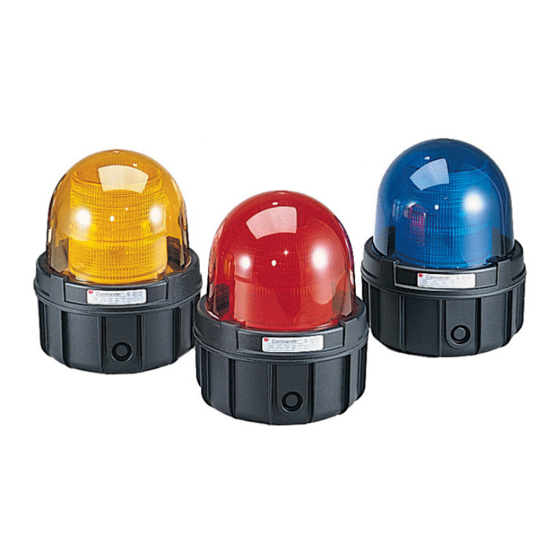
- Page 1 Commander ® Strobe Warning Light Model 371ST-250 Installation and Maintenance Manual 256820E REV. E 811 Printed in U.S.A.
- Page 2 Warranty – Seller warrants all goods for five years on parts and 2-1/2 years on labor, under the following conditions and exceptions: Seller warrants that all goods of Seller's manufacture will conform to any descriptions thereof for specifications which are expressly made a part of this sales contract and at the time of sale by Seller such goods shall be commercially free from defects in material or workmanship.
-
Page 3: Table Of Contents
Contents Safety Messages to Installers ............5 An Overview of Model 371ST-250 ............. 6 Unpacking the Light ................6 Mounting the Light ................7 Pipe Mounting the Light ............8 Surface Mounting the Light ............. 8 Wiring the Light ................. 9 Safety Messages to Maintenance Personnel ........ - Page 4 Contents Figures Figure 1 Mounting options ..............8 Figure 2 Dome and lens assembly removed ........10 Figure 3 Flash tube replacement ............. 13 Model 371ST-250 Strobe Light...
-
Page 5: Safety Messages To Installers
Installation and Maintenance Instructions Safety Messages to Installers It is important to follow all instructions shipped with this product. This device is to be installed by a trained electrician who is thoroughly familiar with the National Electrical Code and/ or Canadian Electrical Code and will follow the NEC and/or CEC Guidelines as well as all local codes. -
Page 6: An Overview Of Model 371St-250
Installation and Maintenance Instructions An Overview of Model 371ST-250 The Federal Signal Model 371ST is a single-flash strobe housed in a Type 4X enclosure. At 60 flashes per minute and 275 effective candela, the Commander is the largest strobe signal in the Federal ®... -
Page 7: Mounting The Light
Installation and Maintenance Instructions Table 1 Electrical and environmental ratings Operating Voltage: 225 Vdc to 300 Vdc Operating Current: 0.25 A Energy Output: 10.0 J Flash Rate: 60 FPM Candela, Peak 625,000 Lamp Life: 10,000 Hours Light Source: Strobe Tube –31 °F to 150 °F Operating Temperature: (–35 °C to 66 °C) -
Page 8: Pipe Mounting The Light
Installation and Maintenance Instructions Figure 1 Mounting options PIPE MOUNT PIPE MOUNT SURFACE MOUNT 371ST-250 LIGHT ASSEMBLY GASKET DRILL THREE 9/32" (7.143 mm) HOLES 1" NPT PIPE MOUNTING SURFACE 1/4" FLATWASHERS 1/4" SCREWS 290A3948B Pipe Mounting the Light Attach the light to the 1-inch NPT pipe by threading the light clockwise on the pipe (Figure 1). -
Page 9: Wiring The Light
Installation and Maintenance Instructions 4. Attach 1" NPT conduit or a suitable user-supplied 1" NPT hub or connector to the conduit entrance in the bottom of the light. 5. Set the light on the gasket and attach it to the mounting surface with the provided 1/4"... -
Page 10: Figure 2 Dome And Lens Assembly Removed
Installation and Maintenance Instructions Figure 2 Dome and lens assembly removed TURN DIE-CAST RING COUNTER-CLOCKWISE DOME ASSEMBLY TO REMOVE DIE CAST RING SCREWS, #10 HEX HEAD (3) STROBE SPINNING ASSEMBLY GASKET GROUND SCREW BASE CONDUIT PLUG (USER SUPPLIED) CONDUIT HUB CONDUIT NUT 290A3949B (USER SUPPLIED) -
Page 11: Safety Messages To Maintenance Personnel
Installation and Maintenance Instructions Route the supply wires (12 AWG to 16 AWG) into housing. Connect the red (+) lead to the positive power source. Connect the black (–) lead to the negative power source. Re-assemble the light and test it for proper operation. Safety Messages to Maintenance Personnel Listed below are some important safety instructions and precautions you should follow:... -
Page 12: Replacing The Flash Tube
Installation and Maintenance Instructions Replacing the Flash Tube SHOCK HAZARD Strobe and HID light systems generate high voltages. Disconnect power from the strobe system and wait at least 5 minutes before opening the unit. Do not apply power to the unit while the unit is open. -
Page 13: Figure 3 Flash Tube Replacement
Installation and Maintenance Instructions HANDLE STROBE AND HALOGEN LAMPS CAREFULLY Strobe and halogen lamps get hot enough to burn you. Always allow these devices to cool before handling them. Halogen and strobe lamps are also pressurized and if broken can result in flying glass. -
Page 14: Cleaning The Dome
Installation and Maintenance Instructions Carefully remove the flash tube from its socket by grasping the connector and lifting upwards using a slight rocking motion. DO NOT TOUCH LAMPS WITH BARE HANDS Oil deposits on the glass portion of a strobe or halogen lamp can cause the glass to fracture during use. -
Page 15: Accessories And Replacement Parts
Conduit Hub Kit, 3/4" NPT K8459138 Close-Up Plug, 1" NPT K8459130 Commander is a registered trademark of Federal Signal Corporation. Myers is a registered trademark of Coopers Industries. T&B is a registered trademark of Thomas & Betts Corporation. Model 371ST-250 Strobe Light... - Page 16 Industrial Systems 2645 Federal Signal Drive • University Park, IL 60484-3167 Tel: 708-534-4756 • Fax: 708-534-4852 Email: elp@federalsignal.com • www.federalsignal-indust.com © 2011 Federal Signal Corporation. All rights reserved.
Need help?
Do you have a question about the Commander 371ST-250 and is the answer not in the manual?
Questions and answers