Advertisement
Quick Links
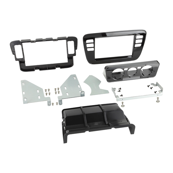
Double DIN Fitting Kit
* Only for models with manual air conditioning and glove box
pos. designation
(1) facia plate
(2) mounting bracket right
(3) mounting bracket left
(4) mounting frame
(5) facia climate control
(6) connection piece ahead
(7) template
(8) mounting bracket complete
(9) washer
(10) flat-head screw (M5x8)
(11) self-tapping screw with collar
10
1
SEAT Mii 2011> *
ŠKODA CITIGO 2011> *
VW up! 2011-2016 *
Part Number.
CT23VW21
CT23VW22
10
3
11
4
Installation Manual
Colour
black
piano black
8
9
10
5
7
6
2
10
1
Advertisement

Subscribe to Our Youtube Channel
Related Manuals for Connects2 CT23VW21


Summary of Contents for Connects2 CT23VW21
- Page 1 Double DIN Fitting Kit Installation Manual SEAT Mii 2011> * ŠKODA CITIGO 2011> * VW up! 2011-2016 * Part Number. Colour CT23VW21 black CT23VW22 piano black * Only for models with manual air conditioning and glove box pos. designation (1) facia plate...
- Page 2 OEM dashboard SEAT Mii / SKODA CITIGO / VW up! with manual air conditioning Pull off the circulating air switch...
- Page 3 Unclip panel Remove panel...
- Page 4 Remove 4 TX20 screws (screws will be required for reassembly) Place two release keys into the provided slots...
- Page 5 Partially remove the OEM head unit from the dashboard...
- Page 6 Disconnect the switch panel...
- Page 7 Disconnect the switch panel Fully remove the OEM head unit from the dashboard...
- Page 8 Disconnect all wiring from the OEM head unit Disconnect all wiring from the OEM head unit...
- Page 10 Pull 3 plugs and 2 Bowden cables out of the air conditioning control panel Pull the Bowden cable out of the air conditioning control unit...
- Page 11 Pull the Bowden cable out of the air conditioning control panel Release the attachment of the Bowden cable...
- Page 12 Open the glove box...
- Page 13 Pull the centre console panel out from the dashboard...
- Page 14 Place the panel on a flat surface Place the facia (5) of the air conditioning control unit centred onto the panel Draw an outline, using the facia (5) of the air conditioning control unit as template Transfer the shape of the facia (5) of the air conditioning control unit onto the panel...
- Page 15 Attention! Draw additional lines with a 5mm gap inside the shape drawn in the previous step Cut out the inner area...
- Page 16 Cut out the inner area...
- Page 17 See below for an image of the removed section Remove all rough edges with sandpaper...
- Page 18 Centre console panel after modification Remove the OEM air channel If a double DIN head unit without CD/DVD drive (mechless unit / maximal install depth 140 mm) is going to be installed, the removal of the OEM air channel is not neccessary: Please proceed to page 20.
- Page 20 Cut out the marked areas Cut out the marked areas...
- Page 21 Cut out the front section of the marked area ca- refully with a depth of app. 3 mm. ATTENTION! Please note the underlying area since it is needed for fixation of the mounting frame later. ATTENTION! This area MUST remain...
- Page 22 ca. 3 mm View of the dashboard after cutting...
- Page 23 Fix the mounting frame (8). Mark the areas inside the mounting frame Remove the mounting frame (8). Cut along the marked areas...
- Page 24 Drill a hole with a diameter of approx. 20 mm for the relocation of the Bowden cables Fix the mounting frame (pos. 8) with the air condition control unit with 4 self-tapping screws with collar (pos. 11)
- Page 25 Place the air conditioning control unit into the dashboard Connect the Bowden cable to the air condtioning control unit...
- Page 26 Reconnect the two Bowden cables to the air conditioning control unit Reconnect the 3 OEM plugs to the air conditioning control unit...
- Page 27 Attach the air condition control unit with 2 self-tapping screws with collar (pos. 11) Push the panel around the centre console.
- Page 28 Fix the facia (pos. 5) on the bottom side with the flat headed screw (pos. 10) and disk (pos. 9)
- Page 29 Install the circulating air switch If a double DIN head unit without CD/DVD drive (mechless unit / maximal install depth 140 mm) is going to be installed, the next steps can be skipped: Please proceed to page 35.
- Page 30 Separate top and bottom of the air channel (see arrows) Bottom of the air channel...
- Page 31 Mark the inner sides, left and right, with the aid of the provided template (pos. 7) Turn around and repeat the procedure on the other inner side...
- Page 32 Cut out the marked sections View of the air channel after after cutting...
- Page 33 New connection piece ahead of air channel Press top and bottom part together using a pincer (see arrows) until they snap in...
- Page 34 Install the air channel...
- Page 35 Place the mounting frame (pos. 4) over the radio opening and mark the position of the two drill holes (see arrows) Drill two holes app. Ø = 3 mm at the marked locations...
- Page 36 Mount both mounting brackets (pos. 2 + 3) and the mounting frame (pos. 4) to the double DIN head unit with the flat-headed screws (M5x8) (Pos. 10) ~ 30 mm We recommend a distance of approx. 30 mm from the brackets to the front side of the unit...
- Page 37 Connect all required circuit points according to the manual of the double DIN head unit. Push the double DIN head unit into the radio opening...
- Page 38 Connect the left switch panel with the designated connector Place the left switch panel into the mounting frame...
- Page 39 Connect the right switch panel with the designated connector Place the right switch panel into the mounting frame...
- Page 40 Attach the mounting frame (pos. 4) with 2 OEM screws (Torx TX 20)* * see page 4 - upper image TX20 Place the facia plate (pos. 1) onto the mounting frame...
Need help?
Do you have a question about the CT23VW21 and is the answer not in the manual?
Questions and answers