Canon VB-R13VE Installation Manual
Hide thumbs
Also See for VB-R13VE:
- Operation manual (263 pages) ,
- Manual (260 pages) ,
- Operation manual (264 pages)
Table of Contents
Advertisement
Quick Links
1
Network Camera
2
BIE-7249-000
/
ENGLISH
Installation Guide
This Installation Guide is comprised of pages [1/2] and [2/2]. Please be sure to read the
included "Safety Precautions" leaflet for correct use. After reading the Installation Guide,
keep it in a safe location.
There are two types of cameras: Hydrophilic Coating Model and Non-hydrophilic Coating Model.
The hydrophilic coating models have a "hydrophilic coating model label" attached on the
product's exterior cover.
Hydrophilic Coating Models
• VB-R13VE (H2)/VB-R12VE (H2)/VB-R11VE (H2)/VB-R10VE (H2)
Non-hydrophilic Coating Models
• VB-R13VE/VB-R12VE/VB-R11VE/VB-R10VE
For handling the hydrophilic coating, be sure to
read the included "Safety Precautions".
Do not remove the protective sheet of the hydrophilic
coating model until installation of the camera is completed.
* Some cameras are not available in certain countries or regions.
Caution
Request a professional installer for all installation work. Never try to install
the camera yourself. Doing so may result in unforeseen accidents such as
dropping the camera or electric shock.
Symbols used in this Installation Guide
: VB-R13VE (H2)/VB-R13VE
: VB-R11VE (H2)/VB-R11VE
Items indicated in the Installation Guide [2/2] with this icon are not included with the
camera, and should be provided by the user.
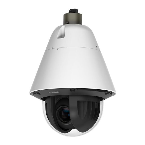
Check Included Items
Camera
Warranty Card
Installation Guide (This document)
Power Interface Cable (BK2-0036-000)
I/O Interface Cable (BK2-0035-000)
Power Interface Cable (Waterproof) (BK2-0039-000)
LAN Connector Set (Waterproof)
Accessories
The following accessories can be purchased separately as necessary. Some accessories are
not available in certain countries or regions.
Ceiling Mounting Kit CM10-VB
Dedicated accessory for attaching the camera to the ceiling.
Wall Mounting kit WM10-VB
Dedicated accessory for attaching the camera to a wall surface.
1.5inch Pipe Adapter PA10-15-VB
Dedicated accessory used to install the camera to the end of pipe that extends from high
ceilings, such as in big-box stores.
Dome Unit DU10-S-VB
Smoked dome cover (Hydrophilic coating is not treated).
Canon AC Adapter PA-V18
Dedicated AC adapter for this camera.
Part Names
1 2 3
4
5
9
11
10
14
1. External device I/O terminals
2. Audio input terminal (Black) (common LINE IN and MIC IN)
3. Audio output terminal (White) (LINE OUT)
5. LAN connector (RJ45, 100Base-TX)
7. Power connection terminal
/ 8. LAN connector
10. Reset switch*
/ 11. Reboot switch / 12. Lens / 13. LED (Orange) / 14. Memory card slot / 15. LED (Blue)*
1
*1 Please refer to the "Operation Guide" for the method to reset the camera.
*2 On: when powered on, during reboot / Off: during normal use
/
/
/
Hydrophilic Coating
Model label
Protective sheet
: VB-R12VE (H2)/VB-R12VE
: VB-R10VE (H2)/VB-R10VE
Before Using This Camera
Safety Precautions
Dedicated Wrench
Waterproofing Tape
6
8
7
12
13
Serial_ _ _ _ _ _ _ _ _ _ _ _ _ _ _ _ _
MAC_ _ _ _ _ _ _ _ _ _ _ _ _ _ _ _ _ _
15
/
/
/ 4. Power connection terminal
/ 6. Attachment lock screws /
/ 9. Dome case /
Notes for When and After Installing the Camera
When Installing the Camera
/
/
Installing the Camera Outdoors
•
/
the "Wrapping the Waterproofing Tape" cautions below for how to wrap.
•
(Waterproof).
• If connecting the camera to the composite pipe by wiring, bridge the
gap using Ceiling Mounting Kit (sold separately) or Wall Mounting kit
(sold separately). When connecting the pipe, apply silicon sealant to
seal it tightly after attaching the pipe to prevent water getting in as necessary.
Wrapping the Waterproofing Tape
Properly waterproof the connections, as shown in the Installation Guide [2/2], using the waterproofing
tape (included). If not properly waterproofed, it may result in water intrusion, thereby causing breakdown.
• To prevent cable connections from shorting out, wrap each individual connection with
insulating tape, and then wrap all of the cables with waterproofing tape. Please refer to the
Installation Guide [2/2] for details on how to wrap the waterproofing tape.
• The camera conforms to the dust-resistant/waterproof specification (IP66), however the
cable ends that connect to external devices are not. Cable connections should be wrapped
with waterproofing tape, if there are any chances that it may get wet.
• Accessories for installation are not dust-proof/waterproof. Wrap the cable connections with
the included waterproofing tape, even if they can fit within the optional unit, because there
could be a chance of the cables getting wet.
After Installing the Camera
When the temperature within the camera is low (heater activation)
When the camera is powered by a 24 V AC/ PoE+ power source, the heater unit can be used.
The heater unit will be activated automatically when the temperature within the camera is low.
The orange LED will be lit, until the camera has warmed up enough to start transferring video.
Once the temperature within the camera has reached the level where it can transfer the video
once again, the orange LED will turn off.
Before Installing the Camera
Separating the Camera and Attachment
Removing and Attaching the Dome Case
Removing the Dome Case
Loosen the screws holding the dome case
in place with the dedicated wrench, and
remove it. Loosen the screws on the dome
case to detach the safety wire.
The screws used for the dome case
fall prevention safety wire and dome
cover holder are as follows.
Connecting the LAN Connector Set (Waterproof)
Connect the LAN cable to the connector.
/
2
Be sure to wrap with waterproofing tape. Please refer to
Please be sure to use the included LAN Connector Set
Attaching the Dome Case
(1) Fix the screws in the dome case and attach
the safety wire.
(2) Align the dome case with the camera body.
(3) Tighten the dome case screws with the
dedicated wrench.
Dedicated
wrench
Note
When you use a memory card,
remove the dome case and
place it in the memory card
slot (SD memory card, SDHC
memory card, and SDXC
memory card are available).
Nominal diameter
M3
7.5 - 8.6 mm
( 0.30 - 0.34 in.)
6.1 - 7.5 mm
( 0.24 - 0.30 in.)
4.9 - 6.1 mm
( 0.19 - 0.24 in.)
568B
568A
Note
Please unhook the safety wire
connected to the camera.
Length
Head shape
6 mm (0.24 in.)
pan head
14 - 16 mm
(0.55 - 0.63 in.)
24 - 26 mm
(0.94 - 1.02 in.)
Wire Manager
Note
• Align the wires with
the terminal settings
according to the
568B/568A color coded
illustration, and insert them
into the wire manager.
• The LAN cable may not
be able to be properly
inserted or removed
from the LAN connector,
if the LAN Connector
Set (Waterproof) is not
used. The cable's water
resistance will not be
maintained as well.
Advertisement
Table of Contents

Related Manuals for Canon VB-R13VE


Summary of Contents for Canon VB-R13VE
-
Page 1: Network Camera
Please refer to the Installation Guide [2/2] for details on how to wrap the waterproofing tape. • VB-R13VE (H2)/VB-R12VE (H2)/VB-R11VE (H2)/VB-R10VE (H2) • The camera conforms to the dust-resistant/waterproof specification (IP66), however the... -
Page 2: Power Connection
15 (49.2) 24 (78.7) 39 (128.0) Use UL cable (UL-1015 or equivalent) for 12 V DC or 24 V AC wiring. © CANON INC. 2019 Printed in Japan The contents of this guide are subject to change without any prior notice. - Page 3 θ ≤ ± ° BIM-7156-000 θ θ θ θ ・ 本書は壁面取付キット を使った壁面設置を記載して WM10-VB います。 ・ 天井設置は壁面設置と同じ手順です。 インチパイプアダプター を使って設置する場合は、 ケーブルを接続してから PA10-15-VB カメラのアタッチメントをパイプに取り付けてください。 詳細は オプションに同梱の設置ガイドをご覧ください。 ・ 親水コーティングモデルの保護シートは、 カメラの設置が完了す るまで取り外さないでください 。 ・ This document describes the wall installation for the Wall Mounting kit WM10-VB. ・...
- Page 4 TORX เป็ น เครื ่ อ งหมายการค้ า ของ Acument Intellectual Properties, LLC TORX T30 드라이버 TORX는 Acument Intellectual Properties, LLC의 상표입니다 . 電源インターフェースケーブル (防水) をご使用の場合は、 キャップは切断 してください。 また、 切断したキャップは保管しておいてください。 電源イン ターフェースケーブル (防水) を使用しない場合は、 キャップをつけないと mm (in./pulg./po) 水が溜まり、 カメラ本体が壊れます。 Printed in Japan © CANON INC 2019...
Need help?
Do you have a question about the VB-R13VE and is the answer not in the manual?
Questions and answers