Table of Contents
Advertisement
Available languages
Available languages
Quick Links
Advertisement
Table of Contents

Subscribe to Our Youtube Channel
Related Manuals for autosen AU001


Summary of Contents for autosen AU001
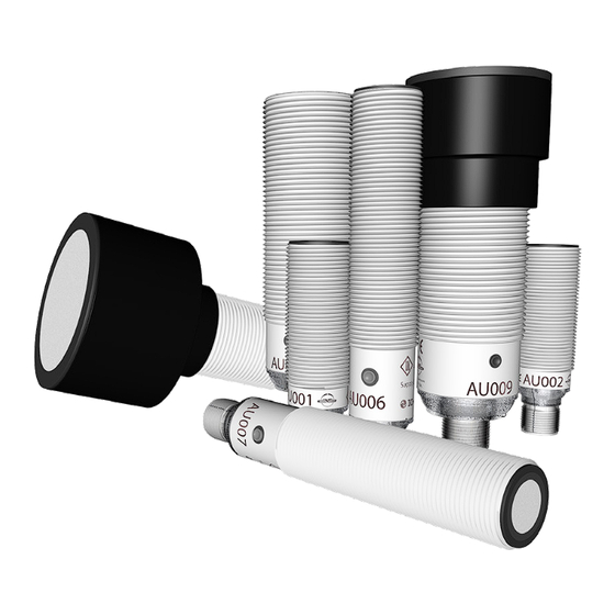
- Page 1 Bedienungsanleitung Ultraschallsensor und Ultraschall Reflextaster Operating instructions Ultrasonic diffuse reflective sensors Notice d‘utilisation Détecteur à ultrasons Istruzioni per l‘uso Sensore a ultrasuoni a diffusione diretta AU001-AU003 autosen AU004-AU010 autosen...
-
Page 2: Bestimmungsgemäße Verwendung
3 Bestimmungsgemäße Verwendung Ultraschallsensoren erfassen berührungslos Objekte unterschiedlichster Materialien. Erkannte Objekte werden, je nach gewähltem Sensor, über Schaltausgänge gemeldet oder deren Abstand mittels proportionalem Analogsignal signalisiert. 4 Montage AU001-AU003 AU004-AU010 1: Status LED P1 (gelb) 3: Einstelltaste 2: Echo-LED (grün) ►... -
Page 3: Elektrischer Anschluss
Colours to DIN EN 60947-5-2 AU001-AU003 OUT1 Schaltausgang OUT2 Teach: Programmierleitung Adernfarben schwarz braun blau Pin 4: IO-Link weiß Colours to DIN EN 60947-5-2 AU004-AU010 OUT1 Schaltausgang - IO-Link OUT2 Analogausgang Technische Daten und weitere Informationen unter → www.autosen.com... - Page 4 ► Taste 2 s...6 s drücken > LEDs blinken (1 Hz). AU001-AU010 Bei nicht erfolgreich abgeschlossener Programmierung kehrt das Gerät in die vorherige Einstellung zurück. AU004-AU010: Dieses Gerät verfügt über eine IO-Link-Kommunikationsschnittstelle. Sobald Informationen zu IO-Link und Einsatzmöglichkeiten → www.autosen.com.
- Page 5 8 Fensterfunktion Abstand P1 > P2 AU001-AU003 ► Programmiermodus des Geräts starten.(7.1) ► Objekt auf Position P1. ► Teacheingang ca. 1 s verbinden. > LED blinkt (2,5 Hz). ► Objekt auf Position P2. ► Teacheingang ca. 1 s verbinden. >...
- Page 6 9 Hysteresefunktion P1 = P2 AU001-AU003 ► Programmiermodus des Geräts starten.(7.1) ► Objekt auf Position P1. ► Teacheingang ca. 1 s verbinden. > LED blinkt (2,5 Hz). ► Objekt auf Position P2. ► Teacheingang ca. 1 s verbinden. > LED blinkt (4 Hz).
-
Page 7: Betrieb
10 Invertieren des Ausgangsverhaltens ► Teacheingang > 6 s verbinden → 7 Leitungsteach. (AU001-AU003) ► Taste > 6 s drücken. (AU004-AU010) > LED blinkt (> 10 Hz). > Ausgangsfunktionen werden invertiert (NO wird NC oder umgekehrt). 11 Werkseinstellung herstellen ► Gerät so ausrichten, dass kein Echo empfangen wird. -
Page 8: Wichtige Begriffe
Restwelligkeit beachten! Gebrauchskategorie DC-Geräte: DC-13 (Steuerung von Elektromagneten) Hysterese Differenz zwischen Ein- und Ausschaltpunkt. Kurzschlussschutz Sind autosen-Sensoren durch getakteten Kurzschlussschutz gegen Überstrom geschützt, kann bei Glühlampen, elektronischen Relais oder niederohmigen Verbrauchern der Kurzschlussschutz ansprechen! Produktnorm IEC 60947-5-2 Schaltpunktdrift Verschiebung des Schaltpunktes bei Veränderung der... - Page 9 14. Mindestabstände zur Montage gleichartiger Geräte 14.1 Gegenüberliegende Montage von Ultraschallsensoren Version Reichweite [mm] Abstand X [mm] AU001 2200 AU002 3000 AU003 1200 3800 AU004 2800 AU005 4000 AU006 1600 5000 AU007 2200 6600 AU008 3500 10500 AU009 6000 18000...
- Page 10 14.2 Montage nebeneinander von Ultraschallsensoren Version Reichweite [mm] Abstand Y [mm] AU001 AU002 AU003 1200 AU004 AU005 AU006 1600 AU007 2200 AU008 3500 1400 AU009 6000 1600 AU010 8000 2150 Die sichere Funktion in der gewählten Applikation ist zwingend zu prüfen.
-
Page 11: Safety Instructions
Ultrasonic sensors detect objects of various materials without any contact. Depending on the selected sensor, detected objects are signalled via switching outputs or their distance is indicated by means of a proportional analogue signal. 4 Installation AU001-AU003 AU004-AU010 3: Set button... -
Page 12: Electrical Connection
Colours to DIN EN 60947-5-2 AU004-AU010 OUT1 Switching output - IO-Link OUT2 Analogue output Technical data and further information at → www.autosen.com 6 Set-up Note the LED behaviour for the set-up: Echo LED green Echo is received. No echo (object / background not detected). - Page 13 If programming has not been completed successfully, the device returns to the previous setting. AU004-AU010: This unit has an IO-Link communication interface. You will find more detailed information about IO-Link and usage at www.autosen.com. 8 Window function, distance P1 > P2 AU001-AU003 Start programming mode of the device.
- Page 14 ②: OUT2 (switching output / analogue output) B: Blind zone P1: Setting point 1 (OUT1) P2: Setting point 2 (OUT2) 9 Hysteresefunktion P1 = P2 AU001-AU003 Start programming mode of the device. (7.1) ► Objekt auf Position P1. ► Teacheingang ca. 1 s verbinden. >...
-
Page 15: Inverting The Output Response
P1: Setting point 1 (OUT1) P2: Setting point 2 (OUT2) P1/P2 10 Inverting the output response ► Connect teach input > 6 s → 7 Wire programming. (AU001-AU003) ► Press button > 6 s. (AU004-AU010) > LED flashes (> 10 Hz). - Page 16 Hysteresis Difference between switch-on and switch-off point. Short-circuit protection autosen sensors are protected against excessive current by means of a pulsed short-circuit protection. The inrush current of incandescent lamps, electronic relays and low resistance loads may cause this protection to cut in and turn the sensor off.
- Page 17 Current consumption Current for the internal supply of DC units. 14. Minimum distances for the installation of identical units 14.1 Opposite installation of ultrasonic sensors Version Range [mm] Distance X [mm] AU001 2200 AU002 3000 AU003 1200 3800 AU004...
- Page 18 14.2 Side-by-side installation of ultrasonic sensors Version Range [mm] Distance Y [mm] AU001 AU002 AU003 1200 AU004 AU005 AU006 1600 AU007 2200 AU008 3500 1400 AU009 6000 1600 AU010 8000 2150 Checking the reliable function in the selected application is imperative.
-
Page 19: Consignes De Sécurité
Des détecteurs à ultrasons détectent sans contact des objets de différentes matières. Suivant le détecteur choisi, les objets détectés sont indiqués via les sorties de commutation ou leur distance est signalée au moyen d‘un signal analogique proportionnel. 4 Montage AU001-AU003 AU004-AU010 1: Etat LED P1 (jaune) 3: Bouton de réglage 2: LED écho (verte) -
Page 20: Raccordement Électrique
Colours to DIN EN 60947-5-2 AU004-AU010 OUT1 sortie de commutation - IO-Link OUT2 analogique Données techniques et plus d‘informations sur→ www.autosen.com 6 Mise en service Pour la mise en service, vérifier le comportement LED: LED écho verte Activé L'écho est reçu. - Page 21 AU001-AU010 En cas de programmation non réussie, l‘appareil retourne au réglage précédent. AU004-AU010: Cet appareil dispose d‘une interface de communication IO-Link. Informations sur IO-Link et possibilités d‘application → www.autosen.com. 8 Fonction fenêtre Distance P1 > P2 AU001-AU003 Démarrer le mode de programmation du périphérique (7.1).
- Page 22 B: Zone aveugle P1: Point de réglage 1 (OUT1) P2: Point de réglage 2 (OUT2) 9 Fonction hystérésis Distance P1 = P2 AU001-AU003 Démarrer le mode de programmation du périphérique (7.1). ► Objet sur position P1. ► Raccorder l‘entrée d‘apprentissage pendant env.
- Page 23 P2: Point de réglage 2 (OUT2) P1/P2 10 Inversion du comportement des sorties ► Raccorder l‘entrée d‘apprentissage pendant > 6 s → 7 Apprentissage par fil. (AU001-AU003) ► Appuyer sur le bouton pendant > 6 s. (AU004-AU010) > LED clignote (> 10 Hz).
- Page 24 12 Fonctionnement ► Vérifier le bon fonctionnement de l‘appareil. > Affichage par LED : LED verte allumée L'écho est reçu. LED jaune allumée La sortie de commutation est commutée. LED verte clignote Court-circuit à la sortie. La distance minimum entre le "boîtier métallique du détecteur de proximité" et une "partie non isolée qui se trouve à...
- Page 25 Différence entre les seuils d'enclenchement et de déclenchement. Protection contre les courts-circuits Les détecteurs d'autosen ayant la protection contre les surcharges et les courts-circuits ont une protection pulsée interne contre les courts-circuits garantissant la non destruction de l'appareil en cas de court-circuit. Ainsi des lampes à...
- Page 26 Version Portée [mm] Distance X [mm] AU001 2200 AU002 3000 AU003 1200 3800 AU004 2800 AU005 4000 AU006 1600 5000 AU007 2200 6600 AU008 3500 10500 AU009 6000 18000 AU010 8000 24000 Il est impératif de contrôler le fonctionnement sûr dans l‘application sélectionnée.
- Page 27 AU008 3500 1400 AU009 6000 1600 AU010 8000 2150 Il est impératif de contrôler le fonctionnement sûr dans l‘application sélectionnée.
-
Page 28: Indicazioni Di Sicurezza
I sensori a ultrasuoni rilevano oggetti di diversi materiali, senza contatto. A seconda del sensore selezionato, gli oggetti rilevati vengono segnalati tramite uscite di commutazione oppure viene trasmessa la loro distanza mediante un segnale analogico proporzionale. 4 Montaggio AU001-AU003 AU004-AU010 1: LED di stato P1 (giallo) 3: Pulsante di regolazione 2: LED eco (verde) ►... -
Page 29: Collegamento Elettrico
AU004-AU010 OUT1 uscita di commutazione - IO-Link OUT2 analogica Dati tecnici e altre informazioni si trovano su → www.autosen.com 6 Messa in funzione Per la messa in funzione è necessario considerare il comportamento dei LED: LED eco verde Acceso L'eco viene rilevata. - Page 30 I LED lampeggiano (1 Hz) AU001-AU010 Con una programmazione non andata a buon fine, il sensore torna all‘impostazione precedente. AU004-AU010: Questo sensore è dotato di un‘interfaccia di comunicazione IO-Link. Informazioni su IO-Link e le possibili applicazioni si trovano su → www.autosen.com.
- Page 31 8 Funzione isteresi P1 > P2 AU001-AU003 Avviare la modalità di programmazione del dispositivo(7.1). ► Oggetto su posizione P1. ► Collegare ingresso teach per circa 1 s. > LED lampeggia (2,5 Hz). ► Oggetto su posizione P2. ► Collegare ingresso teach per circa 1 s.
- Page 32 9 Funzione isteresi P1 = P2 AU001-AU003 Avviare la modalità di programmazione del dispositivo(7.1). ► Oggetto su posizione P1. ► Collegare ingresso teach per circa 1 s. > LED lampeggia (2,5 Hz). ► Oggetto su posizione P2. ► Collegare ingresso teach per circa 1 s.
-
Page 33: Funzionamento
10 Inversione dello stato di commutazione ► Collegare ingresso teach > 6 s → 7 Teach di programmazione. (AU001-AU003) ► Premere il pulsante per > 6 s. (AU004-AU010) > LED lampeggia (> 10 Hz). > Le funzioni dell‘uscita vengono invertite (NO diventa NC o viceversa). - Page 34 14. Distanze minime per il montaggio di dispositivi simili 14.1 Montaggio opposto dei sensori a ultrasuoni modello portata [mm] distanza X [mm] AU001 2200 AU002 3000 AU003 1200 3800 AU004 2800 AU005 4000 AU006 1600 5000 AU007 2200 6600 AU008...
- Page 35 14.2 Montaggio di sensori a ultrasuoni adiacenti portata [mm] distanza Y [mm] modello AU001 AU002 AU003 1200 AU004 AU005 AU006 1600 AU007 2200 AU008 3500 1400 AU009 6000 1600 AU010 8000 2150 La funzione sicura nell‘applicazione selezionata deve essere controllata.
- Page 37 Technische Daten und weitere Informationen unter: Données techniques et informations supplémentaires sur notre site web à: Technical data and further information at: Dati tecnici e altre informazioni si trovano su : www.autosen.com...
Need help?
Do you have a question about the AU001 and is the answer not in the manual?
Questions and answers