Advertisement
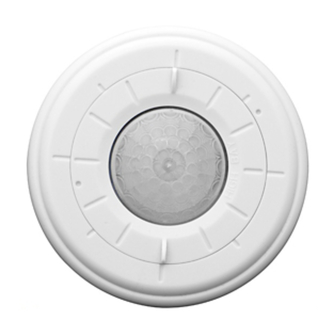
Triple Mount
High Bay Occupancy Sensor
Cat. No. OSFHS-IxW (Sensor)
Ratings:
800VA-6.67A @ 120VAC, 1/4 HP, 50-60Hz
1200VA-4.33A @ 277VAC, 50-60Hz
1500VA-4.32A @ 347VAC, 50-60Hz
32
o
F to 160
o
F
Compatible with electronic and magnetic ballasts,
electronic and magnetic low-voltage ballasts
INSTALLATION INSTRUCTIONS
DI-000-OSFHS-05A
LIMITED 5 YEAR WARRANTY AND EXCLUSIONS
Leviton warrants to the original consumer purchaser and not
for the benefit of anyone else that this product at the time of its
sale by Leviton is free of defects in materials and workmanship
under normal and proper use for five years from the purchase
date. Leviton's only obligation is to correct such defects by repair
or replacement, at its option, if within such five year period the
product is returned prepaid, with proof of purchase date, and
a description of the problem to Leviton Manufacturing Co.,
Inc., Att: Quality Assurance Department, 201 North Service
Road, Melville, N.Y. 11747. This warranty excludes and there
is disclaimed liability for labor for removal of this product or
reinstallation. This warranty is void if this product is installed
improperly or in an improper environment, overloaded, misused,
opened, abused, or altered in any manner, or is not used under
normal operating conditions or not in accordance with any labels
or instructions. There are no other or implied warranties of any
kind, including merchantability and fitness for a particular
purpose, but if any implied warranty is required by the applicable
jurisdiction, the duration of any such implied warranty, including
merchantability and fitness for a particular purpose, is limited to
five years. Leviton is not liable for incidental, indirect, special,
or consequential damages, including without limitation,
damage to, or loss of use of, any equipment, lost sales or
profits or delay or failure to perform this warranty obligation.
The remedies provided herein are the exclusive remedies under
this warranty, whether based on contract, tort or otherwise.
For Technical Assistance Call:
1-800-824-3005 (U.S.A. Only)
www.leviton.com
DI-000-OSFHS-05A
FEATURES
• Multiple mounting options – surface mount (with threaded nipple or key holes), or recessed mount
• Quick-snap nipple allows for installation into standard Double D Knockout on Luminaire without requiring a locknut
• 20 ft. x 60 ft. aisle pattern at 40 ft mounting height
• 360° field-of-view for 20 ft. to 40 ft. High Bay mounting heights
• 360° field-of-view for 8 ft. to 25 ft. Low Bay mounting heights
• Interchangeable 360° High Bay, Low Bay and aisle lens included
• Adjustable Time Delay does not require power to set
• LED indicator light blinks when sensor detects motion
• Adjustable rotating lens for optimizing sensor detection points within the FOV for the specific room
• False detection circuitry reduces nuisance tripping for energy savings
• During a power outage, return-to-last-state design, assures lights ON for safety when occupied and lights OFF for energy
savings when unoccupied
• H.I.S. - Leviton High Inrush Stability uses a robust mechanical latching relay and zero crossing for long life
• Instant startup powers luminaire under 3 seconds to speed up testing on fixture assembly line
• 42" pre-stripped color coded wire leads
• Optional peel and stick mask kit
DESCRIPTION
Leviton's surface mount high bay opccupancy sensor, OSFHS-IxW, is specifically designed for high mounted areas such as
warehouses, manufacturing and other high ceiling applications. It has the flexibility to be surface mounted directly to the front of
a fixture or recess mounted internal to the fixture. It is a self-contained sensor and relay that detects motion using the passive
infrared (PIR) to sense sources (such as a person entering a room) within its field-of-view (monitored space) and automatically
switches lights ON. The controlled lights will remain ON until no motion is detected and the scheduled time-delay has expired.
The sensor is supplied with three interchangeable lens rings that allows the user to select between a 360 degree High Bay/Low
Bay pattern or an aisle pattern.
Cat. No. OSFHS-IxW is UL listed, cUL listed and conforms to California Title 24 requirements. The Sensor's High Bay lens and
aisle lens is designed for 20 ft. to 40 ft. mounting heights for a symmetrical pattern which will provide coverage of 50' to 60'
diameter (refer to Figure 4 and 5). The Low Bay lens is designed for 8 ft. to 20 ft. mounting heights for a symmetrical pattern
which will provide coverage of 30' to 50' diameter (refer to Figure 6). The Sensor is sensitive to the heat emitted by the human
body. In order to initially trigger the Sensor, the source of heat must move from one zone of detection to another.
Note that occupancy sensors respond to rapid changes in temperature, so care should be taken not to mount the device near
a climate control source (i.e. radiators, air exchanges, and air conditioners). Hot or cold drafts will look like body motion to the
device and will trigger it if the unit is mounted too close. It is recommended to mount the Occupancy Sensor at least 6 ft.
away from the heating or cooling ventilation source.
INSTALLATION INSTRUCTIONS
WARNING:
TO BE INSTALLED AND/OR USED IN ACCORDANCE WITH APPROPRIATE ELECTRICAL CODES AND
REGULATIONS.
WARNING:
IF YOU ARE NOT SURE ABOUT ANY PART OF THESE INSTRUCTIONS, CONSULT AN ELECTRICIAN.
WARNING:
CONTROLLING A LOAD IN EXCESS OF THE SPECIFIED RATINGS WILL DAMAGE THE UNIT AND POSE
RISK OF FIRE, ELECTRIC SHOCK, PERSONAL INJURY OR DEATH. CHECK YOUR LOAD RATINGS TO DETERMINE THE
UNIT'S SUITABILITY FOR YOUR APPLICATION.
OTHER CAUTIONS AND NOTES:
1. DISCONNECT POWER WHEN SERVICING LUMINAIRE OR CHANGING BULBS.
2. USE THIS DEVICE WITH COPPER OR COPPER CLAD WIRE ONLY.
3. DO NOT ATTEMPT TO DISASSEMBLE OR REPAIR. CLEAN OUTER SURFACE WITH A DAMP CLOTH ONLY.
TO INSTALL:
NOTE: The OSFHS-IxW is supplied with three lens trim rings. The 360 degree High Bay lens (white color trim ring) is installed at
the factory with the aisle lens (black color trim ring) and the 360 degree Low Bay lens (blue color trim ring) in the carton. Change
the lens for use in aisle or Low Bay applications. See below for changing lens trim ring. The OSFHS-IxW can be mounted to
the surface of a fixture using the 1/2" threaded nipple or using the keyhole slots on the back of the sensor. It can also be recess
mounted internal to the fixture using the slots on the side of the sensor. Reference figures 1, 2 and 3 for dimensions and
mounting specifications.
SENSOR INSTALLATION:
WARNING:
1.
TO AVOID FIRE, SHOCK, OR DEATH: TURN OFF POWER AT CIRCUIT BREAKER OR FUSE AND TEST
THAT THE POWER IS OFF BEFORE WIRING.
2. The sensor comes with three lens rings. NOTE: An optional peel and stick masking kit is included. This circular adhesive label
(with removable wedges) is applied to the OUTSIDE of the sensor lens. Use any number of wedges to alter field-of-view for
your desired application.
3. To change lens, turn trim ring so that the two indented dots line up and pull out by the finger tabs (refer to Figure 7).
4. To insert the black aisle lens, line up the indented dots and indented tabs on underside of lens and insert into key openings
and turn clockwise (refer to Figure 8).
5. Line the finger tabs with the direction of the aisle. The lens will snap into indentation bumps to indicate the lens direction is at
either 90 degree or 0 degree orientation.
Surface Mount Installation:
a. Remove the lock-nut from the threaded nipple and insert the wires and the threaded nipple into a half inch hole of the
luminaire body.
b. Slide the lock-nut over the wires and thread clockwise on to the threaded nipple to secure firmly in place, making sure
the lens is oriented towards the area to be monitored (refer to Figure 1).
Keyhole Mount Installation:
a. Remove the threaded nipple from the back of the sensor by turning counterclockwise.
b. Using the specifications in Figure 2 as a guide, place the sensor and keyhole slots over the screws (use #8-32 pan
head screws) and turn clockwise to lock into place, making sure the lens is oriented towards the area to me monitored.
Recessed Mount Installation:
a. Using the specifications in Figure 3 as a guide, cut a hole per dimensions specified into the luminaire.
b. Slide the sensor into the hole until the clips on the side of the sensor snap into place, securing the sensor.
6. Connect wires per Wiring Diagram as follows: BLACK lead to LINE (Hot); RED lead to LOAD; WHITE lead to LINE (Neutral).
Twist strands of each lead tightly and, with circuit conductors, push firmly into the appropriate wire connector. Screw
connector on clockwise making sure that no bare wire shows below the connector.
7. Restore power at circuit breaker or fuse.
NOTE: Allow approximately 1 minute for charge-up. If the lights turn ON and the LED blinks when a hand is waved in front of the
lens, then the Sensor was installed properly. If the operation is different, refer to the Troubleshooting Section.
The Sensor is factory preset to work without any adjustments. If you desire to change the factory settings, refer to the SETTINGS
section.
SETTINGS
NOTE: Settings should be determined during the installation period. Remove the lens to
access the Time Delay and Sensitivity dials.
Time-Delay: This adjustment controls the amount of time the lights stay ON after the last
detected motion. You may select settings varying from 30 seconds to 30 minutes and any
time in between, no power required.
Sensitivity: Turn dial clockwise to increase detection to small movements. Turn dial
counter-clockwise to decrease detection to small movement.
NOTE: After power is turned ON, allow one minute for the unit to warm up before it will perform the settings.
TROUBLESHOOTING
• Lights will not turn ON
- Site or application interference: Verify LED is flashing and check for manual override switches or obstacles blocking
PIR and FOV.
- Circuit breaker or fuse is OFF: Turn the breaker ON. Ensure the lights being controlled are in working order
(i.e., working bulbs, ballasts, etc.)
- Sensor is wired incorrectly or may be defective: Confirm that the sensor's wiring is done correctly and inspect
visually for problems.
- Lens is dirty or obstructed: Inspect the lens visually and clean if necessary, or remove the obstruction.
• Lights will not turn OFF
- Site or application interference: check for moving fixture, moving parts/items/devices within the FOV.
- Sensor is wired incorrectly or may be defective: Confirm that the sensor's wiring is done correctly and inspect
visually for problems.
- Sensor may be mounted too closely to an air conditioning or heating vent: Move the sensor or close the vent.
- The line voltage has dropped: Perform the necessary tests to ensure the line voltage has not dropped beneath 100V.
• Lights turn OFF and ON too quickly
- Sensor may be mounted too closely to an air conditioning or heating vent: Move the sensor to another location
or close the vent.
- Time delay set improperly: Adjust the TIME DELAY.
• Lights shut OFF while occupied (False OFF)
- Increase TIME DELAY.
• Lamps are being replaced too often
- 10 minutes is optimal for lamp life and energy savings. Increase TIME DELAY to greater than 10 minutes.
Wiring Diagram
Hot (Black)
Line
120-277-347 VAC,
50/60 Hz
Sensor
Neutral (White)
30
30
SEC
MIN
Black
Red
Black
Load
White
White
Advertisement
Table of Contents

Related Manuals for Leviton OSFHS-IxW


Summary of Contents for Leviton OSFHS-IxW
- Page 1 - Time delay set improperly: Adjust the TIME DELAY. NOTE: The OSFHS-IxW is supplied with three lens trim rings. The 360 degree High Bay lens (white color trim ring) is installed at normal operating conditions or not in accordance with any labels •...
- Page 2 Figure 7 Figure 8 Dots Turn clockwise to set aisle direction Insert aisle lens with dots lined up Line up dots Pull up on tab to remove 360° lens (High Bay or Low Bay) © 2012 Leviton Mfg. Co., Inc. DI-000-OSFHS-05A...
- Page 3 COMMENTS : The information in this document is the exclusive PROPRIETARY property of LEVITON MANUFACTURING COMPANY, INC. It is disclosed with the understanding that acceptance or review by the recipient constitues an undertaking by the recipient. (1) to hold this information in strict confidence, and (2) not to disclose, duplicate, copy, modify or use the information for any purpose other than that for which disclosed.
Need help?
Do you have a question about the OSFHS-IxW and is the answer not in the manual?
Questions and answers