Table of Contents
Advertisement
Quick Links
Advertisement
Table of Contents

Related Manuals for CLA-VAL 631-73


Summary of Contents for CLA-VAL 631-73
- Page 1 131-73/631-73...
- Page 5 Powertrol Valve DESCRIPTION This manual contains information for installation, operation and main- tenance of the Cla-Val Co. 100-02 Powertrol, an automatic valve designed for use where independent operating pressure is desired,or when line fluid is unsuitable as an operating medium.
- Page 6 *POSSIBLE TEST SYMPTOM CAUSE PROCEDURE REMEDY FREEDOM OF MOVEMENT Valve fails to Stem stuck in open position. Vent power unit cham- Disassemble, examine close. ber. Apply pressure to all internal parts for The following procedures can be used to determine if the cover chamber.
-
Page 7: If The Disc Has Been Removed, It Is Important That Correct
Preventative Maintenance muriatic acid will soften mineral or scale deposits to assist in removal of The Cla-Val Co Powertrol Valves require no lubrication or packing nuts and general cleaning of parts. Flush the parts thoroughly with water and a minimum of maintenance. However, a periodic inspection immediately after cleaning. -
Page 8: Table Of Contents
1. If the disc has been removed, it is important that correct 9.The Powertrol Valve can be tested for tight closure as well as pressure be on the disc from the disc guide when the the tightness of the seal across the diaphragm. lower stem nut is tight. -
Page 9: Cover
USEFUL INFORMATION OR HINTS ITEM 1. The approximate volume of liquid discharged from PART DESCRIPTION the chamber above the diaphragm when the valve CENTER COVER PLUG moves from the fully closed positions to the fully open COVER PLUG is as follows: STUD NUT PLUG, PIPE, BODY VALVE SIZE... -
Page 10: Power Unit Body
DRIVE SCREW COVER BEARING HOUSING (16" ONLY) * RECOMMENDED SPARE PARTS 1701 Placentia Ave • Costa Mesa CA 92627 Phone: 949-722-4800 • Fax: 949-548-5441 • E-mail: info@cla-val.com • www.cla-val.com CLA-VAL © Copyright Cla-Val 2017 Printed in USA Specifications subject to change without notice. -
Page 11: Diaphragm
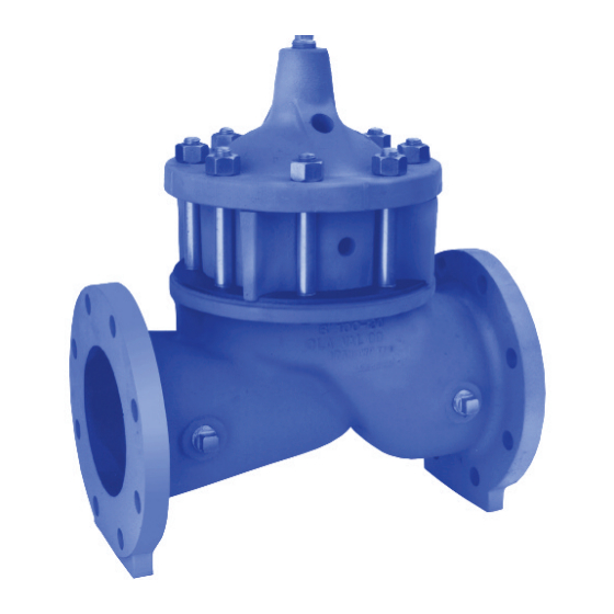
• Service Without Removal From Line • Globe or Angle Pattern • Every Valve Factory-Tested The Cla-Val Model 100-21 is a hydraulically operated, diaphragm actuated, globe or angle pattern valve. It consists of four major components: the body, intermediate chamber, diaphragm assembly and cover. -
Page 12: Stem
® Stem, Nut & Spring Stainless Steel For material options on sizes not listed, consult factory. Cla-Val manufactures valves in more than 50 different alloys. 6"/150 mm Angle, Flanged Options Epoxy Coating - suffix KC Heavy Spring - suffix KH... - Page 13 Functional Data Model 100-21 Inches Valve Size Gal./Min. (gpm.) Globe 1458 7900* 1725 2110 2940 3400* 3500* Pattern Litres/Sec. (l/s.) 32.5 1895 Factor Angle Gal./Min. (gpm.) — — — — — — — — — Pattern Litres/Sec. (l/s.) — — —...
-
Page 14: Body
Service and Installation Cla-Val Control Valves operate with maximum efficiency when mounted in horizontal piping with the main valve cover UP, however, other positions are acceptable. Due to component size and weight of 10 inch/250 mm and larger valves, installation with cover UP is advisable. We recommend isolation valves be installed on inlet and outlet for maintenance. - Page 15 BULLETINS INSTALLATION AND 8210 MAINTENANCE INSTRUCTIONS 8211 2-WAY INTERNAL PILOT OPERATED SOLENOID VALVES ASCO DIAPHRAGM TYPE - 3/8, 1/2 AND 3/4 N.P.T. FORM NO. V-5848 NORMALLY CLOSED OPERATION DESCRIPTION POSITIONING/MOUNTING This valve is designed to perform properly when mounted in any position. Bulletin 8210’s are 2-way, normally closed internal pilot operated solenoid However, for optimum life and performance, the solenoid should be valves.
-
Page 16: Seat
IMPROPER OPERATION 1. Faulty Control Circuit: Check the electrical system by energizing the solenoid. A metallic click signifies that the solenoid is operating. Absence of the click indicates loss of power supply. Check for loose or blown-out fuses. open circuited or grounded coil. broken lead wires or splice connections. - Page 17 Bulletin 8210 -- A-C Construction General Purpose Solenoid Enclosure Shown Figure 2. For Explosion-Proof/Watertight Solenoid Enclosure used on Bulletin 8211, see Form No. V-5391.
- Page 18 CLA-VAL P.O. Box 1325 • Newport Beach, CA 92659-0325 • Phone: 949-722-4800 • Fax: 949-548-5441 • E-mail: claval@cla-val.com • Website cla-val.com © Copyright Cla-Val 2011 Printed in USA Specifications subject to change without notice. N-V5848 (R-3/2011)
-
Page 19: Nameplate
BULLETINS INSTALLATION AND 8262 MAINTENANCE INSTRUCTIONS 2-WAY DIRECT ACTING SOLENOID VALVES ASCO NORMALLY CLOSED OPERATION -- 1/4 N.P.T. FORM NO. V-5927 DESCRIPTION WIRING Wiring must comply with Local and National Electrical Codes. Solenoid Bulletin 8262’s are 2-way normally closed, direct acting solenoid valves housings are provided with a 7/8 diameter hole for 1/2 inch conduit. - Page 20 FIGURE 4 SHOWS A SOLENOID WITH A WATT RATING OF 105 A-C, 11.2 D.C OR 16.7 A.C 1. Remove retaining cap or clip, nameplate and housing. CAUTION: When metal retaining clip disengages, it will spring upward. 2. Slip spring washer, insulating washer and coil off the solenoid base sub-assembly.
- Page 21 NOTE: A-C (ALTERNATING CURRENT) CONSTRUCTION SHOWN. FOR A-C CONSTRUCTION, EITHER END OF THE SPRING MAY BE INSTALLED INTO TOP OF CORE ASSEMBLY. FOR D-C (DIRECT CURRENT) CONSTRUCTION, INSTALL WIDE END OF CORE SPRING IN CORE ASSEMBLY FIRST, CLOSED END OF CORE SPRING PROTRUDES FROM TOP OF CORE ASSEMBLY. Bulletin 8262 (6 A-C, 9.7 D-C or 9 Watts A-C) General Purpose Solenoid Enclosure Shown Figure 3...
- Page 22 For Explosion-Proof/Watertight Solenoid Enclosure, See Form No. V-5380 CLA-VAL P.O. Box 1325 • Newport Beach, CA 92659-0325 • Phone: 949-722-4800 • Fax: 949-548-5441 • E-mail: claval@cla-val.com • Website cla-val.com © Copyright Cla-Val 2011 Printed in USA Specifications subject to change without notice.
- Page 23 CLA-VAL P.O. Box 1325 • Newport Beach, CA 92659-0325 • Phone: 949-722-4800 • Fax: 949-548-5441 • E-mail: claval@cla-val.com • Website cla-val.com © Copyright Cla-Val 2011 Printed in USA Specifications subject to change without notice. PL-CK2 (R-3/2011)
- Page 25 Cla-Val Main Valve. CLA-VAL 1701 Placentia Ave • Costa Mesa CA 92627 Phone: 949-722-4800 • Fax: 949-548-5441 • E-mail: info@cla-val.com • www.cla-val.com N-CV (R-06/2018) Copyright Cla-Val 2018 Printed in USA Specifications subject to change without notice.
-
Page 26: Parts List
Stem BAR STOCK O-Ring CONFIGURATION Housing CLA-VAL 1701 Placentia Ave • Costa Mesa CA 92627 Phone: 949-722-4800 • Fax: 949-548-5441 • E-mail: info@cla-val.com • www.cla-val.com PL-CV (R-03/2011) Copyright Cla-Val 2018 Printed in USA Specifications subject to change without notice. ©... - Page 27 DESCRIPTION The Model X117C Valve Position Transmitter is designed to provide analog signal (4 - 20 mA, 2 wire) output of valve position for Cla-Val Main Valves. A stem extension is fitted to the main valve stem with the position transmitter mechanically linked to it. The valve stem is mechanically linked to the electronics for an output signal that is in direct proportion to valve position.
- Page 28 After loosening the setscrew, move the spool by hand (up and Refer to calibration equipment (see Step 6) and adjust potentiometer down) to check that the roller and spool are in alignment throughout marked “SPAN” until the meter reads 20 mA. A clockwise turn entire valve stroke.
- Page 30 R L 2 is current monioring instrumentation load CLA-VAL P.O. Box 1325 • Newport Beach, CA 92659-0325 • Phone: 949-722-4800 • Fax: 949-548-5441 • E-mail: claval@cla-val.com • Website cla-val.com © Copyright Cla-Val 2011 Printed in USA Specifications subject to change without notice.
- Page 31 Electronic Control of Hydraulic Valves The 131VC-1 Electronic Control System is designed to work in Key Advantages conjunction with Cla-Val 131 Series hydraulic control valves— a combination that takes advantage of the simplicity of • Proven reliable hydraulic control valve hydraulic valve operation and the control possibilities available •...
- Page 32 How it Works 3. Valve Actuation 1. Set-Point Command 2. Feedback and Comparison Electronic Valve Controller actu- Set-point command is received from a The Electronic Valve Controller compares ates the solenoid controls, causing the remote location or entered via the key the feedback signal from the transmitter valve to modulate as needed to regain pad into the Electronic Valve Controller.
- Page 33 Features Specifications Alarm - Programmed to signal when system conditions exceed a desired Control Input: value or in the event of a system component failure. It can be configured to be latching or non-latching, normally open or normally closed contact 4-20 mA full scale (others optional) with deadbands.
- Page 34 How To Order O r d e r O u t p u t 1 : C o n t r o l C o d e e c h a n i c a l R e l a y ( 5 a m p ) n a l ( m i l l i a m p ) e R e l a y (...
- Page 35 Programmable Control Features VALVE RESPONSE TIME Faster Slower DEVIATION BAND DEVIATION BAND 100% VALVE SENSITIVITY Higher Lower SOLENOID SOLENOID CYCLE TIME CYCLE TIME Dead Band Valve Solenoid Feature in blue "On" Time are user programmable SET-POINT Full Programmable Control of Valve Sensitivity and Valve Response Solenoid Cycle Time Designed with duplex output circuits (one to control the valve...
- Page 36 For applications requiring control of valve position, use the from the tank level transmitter as the remote set-point. This sig- optional Cla-Val X117 Valve Position Transmitter. This provides nal is then compared with the signal generated by an optional the feedback signal to the controller. A computer or program-...
- Page 37 Power Failure Options POWER SUPPLY Power POWER Power POWER 131-01 Valve 131-01 Valve Direct Voltage Electronic Control Maintain Valve Position Customer supplied battery power, with a continuous charging When there is a power failure, using the standard Model 131-01 system, operates the valve solenoids and controller in the event Control Valve, the pilot control solenoids lock in the closed of power failure.
- Page 38 As the feedback signal The Electronic Control System shall be the Cla-Val Model 131VC-1 as approaches the set-point, the solenoid output will pulse on and off to manufactured by Cla-Val, Newport Beach, CA.
- Page 39 INLET SIZE & inquiries concerning valve operation, it is important to CAT NO. EINTRITT STOCK properly identify Cla-Val products already in service CODE ENTREE by including all nameplate data with your inquiry. MFD. BY CLA-VAL ENTRADA Pertinent product data includes valve function, size, NEWPORT BEACH, CALIF, U.S.A.
-
Page 40: Limited Warranty
This product. Cla-Val shall not be liable for any damages or charges for warranty is expressly conditioned on the purchaser’s providing written labor or expense in making repairs or adjustments to the product. - Page 41 INSTALLATION / OPERATION / MAINTENANCE REPAIR KITS MODEL Model 100-01 Hytrol Main Valve BUNA-N MATERIAL RUBBER KIT REPAIR KIT REBUILD KIT STUD & NUT KIT STOCK NO. STOCK NO. STOCK NO. STOCK NO. 3/8” 9169801K 21176614B 21176633J 1/2” 9169802H 21176602F 21176615A 21176634H 3/4”...
- Page 42 When ordering, please give complete nameplate data of the valve and/or control being repaired. MINIMUM ORDER CHARGE APPLIES CLA-VAL 1701 Placentia Ave • Costa Mesa CA 92627 Phone: 949-722-4800 • Fax: 949-548-5441 • E-mail: info@cla-val.com • www.cla-val.com © Copyright Cla-Val 2018 Printed in USA Specifications subject to change without notice.
Need help?
Do you have a question about the 631-73 and is the answer not in the manual?
Questions and answers