Advertisement
Quick Links
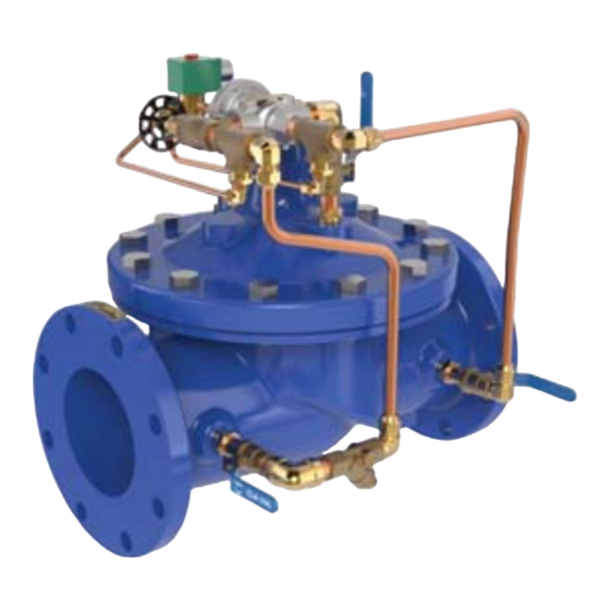
INTRODUCTION
The Cla-Val Model 136-03/636-03 Solenoid Control Valve is an
automatic valve designed to either close drip tight or open fully by
means of a Three-Way Solenoid Control. It is a hydraulically oper-
ated, solenoid controlled, diaphragm type globe or angle valve.
INSTALLATION
1. Allow sufficient room around the valve assembly to make
adjustments and for disassembly.
Note: Before the valve is installed, the pipeline should be
flushed to remove all chips, scale and foreign matter.
2. It is recommended that gate or line block valves be installed
upstream and downstream of the Model136-03/636-03 to facilitate
isolating the valve for preventive maintenance.
3. Place the valve in the line with flow in the direction of flow
arrows or by the inlet nameplate. Check all fittings and hardware
for proper makeup and that no apparent damage is evident. Be
sure main valve cover nuts/bolts are tight. Pressure in some appli-
cations can be very high so be thorough in checking and inspect-
ing for proper installation and makeup.
4. Cla-Val Valves operate with maximum efficiency when mounted
in horizontal piping with the cover UP; however, other positions are
acceptable. Due to size and weight of cover and internal compo-
nents of six inch valves and larger, installation with the cover up is
advisable. This makes periodic inspection of internal parts readily
accessible.
5. Caution must be taken in the installation of this valve to insure
that galvanic and/or electrolytic action does not take place. The
proper use of dielectric fittings and gaskets are required in all sys-
tems using dissimilar metals.
6. Comply with local and national electrical codes when wiring the
Solenoid Control.
OPERATION AND START-UP
1. Prior to pressurizing the valve assembly make sure the neces-
sary gauges to measure pressure in the system are installed as
required by the system engineer. A Cla-Val Model X101 Valve
Position Indicator can be installed in the center cover port to pro-
vide visual indication of the valve diaphragm assembly position
during start-up.
CAUTION: During start-up and test procedures a large volume of
water may be discharged downstream. Check that the downstream
venting is adequate to prevent damage to personnel and equip-
ment. If the main valve closes too fast it may cause surging in
upstream piping.
2. If isolation valves (B) are installed in pilot system open these
valves. (see schematic).
3. The three-way Solenoid Control applies or relieves pressure in
the 102C-3H three-way valve cover chamber. This, in turn, applies
or relieves pressure in the main valve cover chamber. The follow-
ing action takes place:
E
SOLENOID CONTROL
(2)
T
HREE
POSITION
FLOW
V
ALVE
ENERGIZED
1
2
COM.
TO
3
1
DE-ENERGIZED
N.C.
TO
Note: Solenoids are not reversible because of different internal
construction between Energize to open and De-energize to open
solenoids.
T
O
D
-E
NERGIZED
O
PEN
E
NERGIZED
136-03 S
136-03 S
ERIES
-W
M
T
-W
AY
AIN
HREE
F
(3)
V
(1)
V
F
LOW
ALVE
ALVE
LOW
N.O.
O
N.C.
TO
PEN
TO
COM.
C
COM.
TO
LOSED
TO
INSTALLATION / OPERATION / MAINTENANCE
MODEL
Solenoid Control Valve
4. Check that solenoid (2) is set to close main valve. Slowly open
the gate or block valve upstream of the valve.
5. Carefully loosen tube fittings at highest points and bleed air
from system. Carefully loosen the plug at top of main valve cover.
If X101 Valve Position Indicator is installed, carefully open the
bleed valve at top of Indicator. Bleed air from cover and tighten
plug or bleed screw. Tighten tube fittings.
6. Slowly open downstream gate or block valve. Check the oper-
ation of the valve by energizing and de-energizing the solenoid.
The valve should open fully and close drip tight.
Need minimum 5 psi differential under flowing coditions.
MAINTENANCE
1. Cla-Val Valves and Controls require no lubrication or packing
and a minimum of maintenance. However, a periodic inspection
schedule should be established to determine how the fluid han-
dled is affecting the efficiency of the valve assembly. Minimum of
once per year.
2. Repair and adjustment procedures of the Cla-Val Hytrol main
valve and control components are included in a more detailed
IOM manual. It can be downloaded from our web site (www.cla-
val.com) or by contacting a Cla-Val Regional Sales Office.
3. When ordering parts always refer to the catalog number
and stock number on the valve nameplate.
SYMPTON
Main Valve
Fails to Close
T
O
O
PEN
ERIES
M
AIN
Main Valve
AY
Fails to Open
V
(3)
1
ALVE
C
COM.
LOSED
O
N.O.
PEN
Main Valve
Vibrates when
Closed
136-03/636-03
PROBABLE CAUSE
No flow condition
Too low pressure differential
across valve
Need minimum 5psi differential
under flow coditions
Closed isolation valves in pilot
system, or in main line
Lack of cover chamber pressure Check upstream
Diaphragm damaged
Mechanical obstruction
Object lodged in valve
Worn disc
Badly scored seat
CNA needle valve closed
Closed isolation valves in pilot
system, or in main line
Insufficient line pressure
Diaphragm assembly inoperative
Air in cover
REMEDY
Inspect downstream piping for
closed valve or obstruction
Restrict valve opening with
Cla-Val X102A
limiting assembly
(Contact Cla-Val)
Open valves
pressure, tubing needle
valves for restriction
Replac diaphragm
Remove obstruction
Replace disc
Replace seat
Open this speed control to
allow pressure to cover
Open valves
Clean & polish stem
Replace and defective or
damaged parts
Bleed all air from valve
Advertisement

Related Manuals for CLA-VAL 136-03


Summary of Contents for CLA-VAL 136-03
- Page 1 MODEL Solenoid Control Valve INTRODUCTION The Cla-Val Model 136-03/636-03 Solenoid Control Valve is an automatic valve designed to either close drip tight or open fully by means of a Three-Way Solenoid Control. It is a hydraulically oper- ated, solenoid controlled, diaphragm type globe or angle valve.
- Page 2 Repair Parts *SUGGESTED REPAIR PARTS For a more detailed IOM Manual go to www.cla-val.com or contact a Cla-Val Regional Sales Office. 1701 Placentia Ave • Costa Mesa CA 92627 Phone: 949-722-4800 • Fax: 949-548-5441 • E-mail: info@cla-val.com • www.cla-val.com CLA-VAL ©...
Need help?
Do you have a question about the 136-03 and is the answer not in the manual?
Questions and answers