
Related Manuals for Lamona LAM9500


Summary of Contents for Lamona LAM9500
- Page 1 Downdraft Induction Hob LAM9500 Instructions and Installation www.howdens.com/appliance-registration...
- Page 2 See back page for product serial number...
-
Page 3: Table Of Contents
Contents 2. General 6. Cleaning & Care 2.1 For your information 6.1 Glass ceramic hob 6.2 Grease filters 3. Safety Instructions & Warnings 3.1 For connection and operation 7. Trouble shooting 3.2 General information about the hob 3.3 User Safety 8. -
Page 4: General
Safety & Warnings 2 General hob for which no liability will be assumed. 2.1 For your information... • It is essential that after using a cooking zone you switch it off with the respective minus Please read this manual carefully before using your appliance. -
Page 5: User Safety
Safety & Warnings induction hob. Caution! Risk of burns! Non- • Only a little moisture is removed from magnetisable objects (e.g. gold or silver the vapours in the convection air mode. rings) are not affected. This is why a sufficient supply of fresh air must always be provided, e.g. -
Page 6: Explanation For Symbols & Indications
Safety & Warnings 3.4 Explanation for symbols and indications WARNING OF ELECTRICAL ENERGY The appliance was produced according to state of the RISK OF FATAL INJURY! art technology. Machines nevertheless give rise to risks Live components have been installed near which cannot be constructively avoided. -
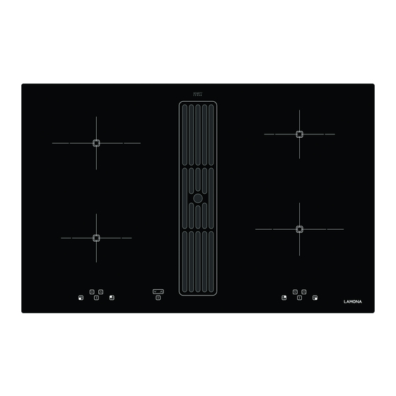
Page 7: Operation
Operation 4 Appliance description The decorative design may deviate from the illustrations. 10. Plus key (raise) / Minus key (lower) 11. Power setting indicator 1. Induction cooking zone front left 12. Timer indicator 2. Induction cooking zone back left 13. Standby key 3. - Page 8 Operation Operating the hob with the sensor keys Minus key / Plus key (10) The glass ceramic hob is operated with touch control These keys are used to set the cooking levels, the sensor keys. The sensor keys are operated as follows: automatic switch-off device and the minute minder.
-
Page 9: The Induction Hob
Operation 5 Operation 5.3 Operation time limit (Safe off) 5.1 The induction hob The induction hob has an automatic time limit function. The duration of continuous use of each cooking zone The hob is equipped with an induction cooking mode. depends on the power level selected (see chart). -
Page 10: How To Cut Power Consumption
Operation 5.6 Cookware for induction hobs 5.7 How to cut power consumption Cookware for induction cooking zones must be made of The following are a few useful hints to help you cut your metal and have magnetic properties. The base must be consumption of energy and use your new induction hob sufficiently large. -
Page 11: Operating The Keys
Operation 5.10 Switching the appliance into the standby mode This standby key is used to switch the entire hob operational. It is, as it were, the main switch. An automatic test of the controls will be carried out first of all, and the displays will light up briefly. -
Page 12: Child Lock
Operation 5.15 Child lock The child lock serves to prevent children from switching on the hob accidentally or intentionally. The controls are blocked here. Switching on the child lock 1. Press the ON/OFF key in order to switch on the hob. -
Page 13: Automatic Switch Off (Timer)
Operation 5.16 Automatic switch-off (timer) The automatic switch-off device is used to automatically switch off any cooking zone after an adjustable period of time. Cooking times ranging from 01 to 99 minutes can be set. 1. Switch on the hob. Switch on one or more cooking zones and select the required power settings. -
Page 14: Power Boost
Operation 5.18 Power boost The power boost setting makes additional power available for induction cooking zones. A large quantity of water can be brought to the boil very quickly. The power boost setting operates for 5 minutes, after which the power level is automatically reduced to power setting 9. -
Page 15: Using The Fan
Operation 5.20 Using the fan The fan is located in the middle of the hob with the extractor facing downwards. Important: Do not put the cover onto the induction hob! Risk of burning! 5.20.1 Switching the fan on and off 1. -
Page 16: Cleaning & Care
Cleaning & Care 6 Cleaning and care residual moisture resulting from cooking and cleaning can escape if necessary when the fan is not in operation • Switch the hob off and let it cool down before you and the cover is on. clean it. -
Page 17: Troubleshooting
Troubleshooting 7 What to do if trouble occurs? guaranteed. Interference with and repairs to the appliance by un- The symbol or Er03 will blink and a time-limited qualified persons are dangerous as they can result in an continuous signal will sound. electric shock or a short circuit. -
Page 18: Instructions For Assembly
Instructions For Assembly 8 Instructions for assembly • When installing a hob into an uneven worktop, e.g. with a ceramic or similar covering (tiles etc.), the seal 8.1 Safety instructions for kitchen unit fitters on the hob is to be removed and the seal between the •... -
Page 19: Clearances & Dimensions
Instructions For Assembly 8.3 Clearances & dimensions No shelf or overhang of combustible material should be closer than 650mm directly above the hob. There must be a minimum clearance of 50mm between the rear edge of the hob and the rear wall. This clearance must be maintained up to 650mm above the worktop (unless otherwise stated in your extractor manual). -
Page 20: Installation
Instructions For Assembly 8.4 Installation Dimensions in mm 750+1 min.50 min.50 Minimum distance to adjacent walls Opening dimensions Cutout dimensions Outer dimensions of the hob Important: There is a risk of breakage if the hob is canted or subjected to stress during installation! In the case of thin worktops i.e less than 38mm pack out the brackets as required. -
Page 21: Illustrations Kitchen Cabinets
Instructions For Assembly 8.5 Illustrations kitchen cabinets 8.6 800 Base Cabinet 616mm 335mm 50mm 46mm 165mm 170mm 616mm 335mm 50mm 46mm 165mm 170mm 170mm >150mm 170mm >150mm >370mm 220mm >370mm 575mm 160mm 220mm 575mm 160mm 800mm 800mm 100mm 96mm 100mm 96mm 140mm 255mm... -
Page 22: Extraction Air System
Instructions For Assembly 8.8 Extraction air system assembly Exhaust air duct components (inclusive): The hob and the fan can be connected with a flexible hose or with the addition of flat ducting for island configurations. Flexi duct can be cut with a knife. Shorten the flat duct with a fine saw if necessary, smooth ends and ensure no bumps. -
Page 23: Pole Fan Plug Adaptor
Instructions For Assembly 8.9 7-pole fan plug connector DANGER Risk of electric shocks The fan plug connection must be made before the mains connection! The appliance must be cut off from the electricity supply before the plug retainer is opened again. The appliance may only be connected to the mains once the plug connection has been made. -
Page 24: Hob Fan Installation
Instructions For Assembly 8.11 Hob fan installation connection cable in the factory. • Connection to the mains is carried out in accordance • The product may only be connected by a qualified with the circuit diagram. fitter according to applicable local regulations. The same applies for the connections. -
Page 25: Technical Data
Instructions For Assembly 9 Decommissioning and disposal of the 8.12 Technical Data appliance Hob dimensions 9.1 Switching the appliance off completely height/ width/ depth mm 170 x 800 x 520 The appliance is to be put out of operation when its Cooking zones useful life has finally come to an end. -
Page 26: Product Guarantee
Call the Depot number on your Proof of Purchase Document supplied with the product / kitchen. Call the LAMONA Service Line on 0344 460 0006 * Product installed within a domestic kitchen or non-domestic kitchen where 8 or fewer people are using the appliance. - Page 28 Product serial number (Place sticker here) ISSUE v1 060319 2406125000...
Need help?
Do you have a question about the LAM9500 and is the answer not in the manual?
Questions and answers