Table of Contents
Advertisement
Available languages
Available languages
Quick Links
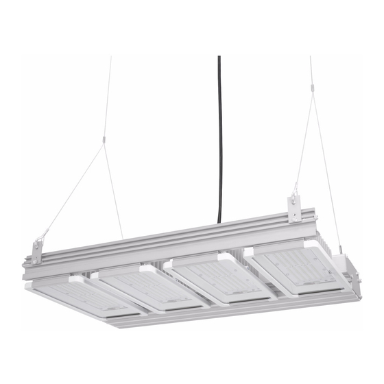
Industrial High Bay LED Luminaires
Installation & Maintenance Information
APPLICATION
*CE suffix does not include SO cable.
To avoid the risk of fire, or electric shock, this product should be installed,
inspected and maintained by a qualified electrician only, in accordance with all
applicable electrical codes. *Verify power wire (SOOW cable) is in accordance
with all applicable electrical codes.
To avoid electric shock:
Be certain electrical power is OFF before and during installation and maintenance.
Luminaire must be supplied by a wiring system with an equipment grounding
conductor.
To avoid burning hands:
Make sure lens and housing are cool when performing maintenance.
To avoid product degradation:
Do not operate in ambient temperatures above those indicated on the luminaire
nameplate.
Use proper supply wiring as specified on the luminaire nameplate.
Avoid use in environments containing sulfur, chlorine or other halides, methyl
acetate or ethyl acetate, cyanoacrylates, glycol ethers, formaldehyde or butadiene.
Mount luminaire no less than 36 inches from ceiling.
Make sure the supply voltage is within the voltage range stated on the nameplate.
Aircraft cable mounting is recommended for dry locations only.
INSTALLATION – PENDANT MOUNT
1.
Install the pendant mount bracket with the hardware provided, four (4) ¼-20
screws and four (4) ¼-20 nuts (see Figure 1). Center the pendant mount
bracket on the luminaire (see Figure 1). Measure from each end of the
luminaire to the edge of the pendant mount on each side. The distance from
side to side should be equal or within 1/16" to each other. Tighten the ¼-20
screws to 65 in.-lbs. and tighten the 10-24 screws to 21 in.-lbs. DO NOT
REMOVE MOUNTING TAB RETENTION SCREWS. If mounting tab retention
screws are removed, make sure to re-install and tighten to 65 in.-lbs. torque.
2.
Thread the locknut onto the ¾" NPT conduit threads as far up the threads as
possible.
3.
Place the luminaire onto the conduit at the hole located in the center of the
pendant mount bracket. Install the throat bushing onto the conduit and rotate
the luminaire to the correct position. Tighten the throat bushing first (42 ft.-
lbs.) and then the lock nut (hand tight plus a quarter turn). After tightening both
wrench tight, tighten the set screw to 9 in.-lbs.
4.
Remove all four (4) screws from the end cap of the luminaire closest to the
wiring entry gland. Install the SOOW cable from the conduit into the cord grip
and connect the input wires to the driver input wires of the luminaire according
to the wiring diagram (see Figure 5). For dimmer applications, remove plug
from driver housing cover and use a separate cord grip wire according to the
wiring diagram (see Figure 5). Tighten cord grip(s) wrench tight to secure
wires into place. Install the driver housing end cap and tighten the four (4)
screws until bottomed.
SAVE THESE INSTRUCTIONS FOR FUTURE REFERENCE
WARNING
WARNING
WARNING
CONFIGURATIONS
VOLTAGE OPTIONS
POWER WIRE
(SOOW CABLE)
DIMMER WIRE
ENTRY LOCATION
MOUNTING TAB
RETENTION SCREWS
WIRE ACCESS
LOCATION
(END CAP)
END CAP SCREWS
Lock Screw
Figure 1 – Pendant Mount Connection
Secondary retention may be considered for pendant mount applications for
added security and is recommended in applications where high vibrations are
present. Four (4) additional holes are included on the pendant mount bracket
that may be used for secondary retention and either the aircraft cable (in dry
locations) and jack chain mounts are suitable for this purpose.
AIRCRAFT CABLE
AIRCRAFT CABLE MOUNTING IS INTENDED FOR DRY LOCATIONS ONLY.
1.
Mounting tabs are located 1" from each end of the luminaire from the factory.
If mounting tabs need to be relocated or become loose, tighten the 10-24
screws to 21 in.-lbs. (see Figure 2) before hanging the luminaire. Mounting
tab retention bolts should be tightened to 65 in.-lbs. in all four corners of the
luminaire. Mounting tabs should be placed equal distance from the ends of
the luminaire to ensure the luminaire hangs level.
2.
Install two (2) aircraft cable assemblies to the luminaire with one aircraft cable
assembly at each end of the luminaire as shown in Figure 2. Do not exceed
an angle greater than 30° between the cables and the gravity line. Adjust
the length of the aircraft cable assembly to ensure the luminaire hangs level.
Mount the luminaire a minimum of 36 inches away from the ceiling. Refer to
B-Line FIS-164 Instruction Sheet for further details and information.
3.
Use the factory installed wire (SOOW cable) for electrical connection to the
appropriate junction connection. See WIRING section for more information.
CONDUIT
SECONDARY
LOCK NUT
RETENTION
HOLES
PENDANT MOUNT
BRACKET
MOUNTING TABS
1/4-20 SCREWS
1/4-20 NUTS
EQUAL
DIST.
EQUAL
10-24 SCREWS
DIST.
Lock Nut
Throat Bushing
WARNING
IF 1726
Advertisement
Table of Contents

Related Manuals for Eaton CROUSE-HINDS Industrial High Bay


Summary of Contents for Eaton CROUSE-HINDS Industrial High Bay
- Page 1 Industrial High Bay LED Luminaires Installation & Maintenance Information IF 1726 SAVE THESE INSTRUCTIONS FOR FUTURE REFERENCE APPLICATION CONFIGURATIONS *CE suffix does not include SO cable. VOLTAGE OPTIONS WARNING CONDUIT SECONDARY LOCK NUT RETENTION HOLES To avoid the risk of fire, or electric shock, this product should be installed, PENDANT MOUNT BRACKET POWER WIRE...
- Page 2 INPUT POWER CONNECTIONS DC OUT + (RED) DC OUT + (RED) DC OUT-(EUC-075S070DT-BLACK) DC OUT - (BLACK) (ESC-075S070DT - BLUE) LINE (BLACK) LINE (BLACK) NEUTRAL (WHITE) NEUTRAL (WHITE) SOOW CABLE 30 ° MAX AIRCRAFT DIM+ (PURPLE) CABLE ASSY WITH HOOKS INPUT DIMMING CONNECTIONS DIM- (EUC-075S070DT - GREEN) (ESC-075S070DT - GREY)
-
Page 3: Driver Replacement
WEIGHTS: DC OUT + (RED) DC OUT - (BLUE) DIM+ (PURPLE) DIM- (GREY) DC OUT + (RED) CONFIGURATION DC OUT + (RED)* LINE (BLACK) DC OUT - (BLACK) LINE (BLACK) DC OUT - (BLACK) PENDANT MOUNT (LBS.) 11.2 LINE (BLACK) NEUTRAL (WHITE) DC OUT + (RED) AIRCRAFT CABLE (LBS.) -
Page 4: Replacement Parts
REPLACEMENT PARTS ever, should the need for replacement parts arise, they are available through your ACCESSORY KITS Description Parts Ordered Separately 40” Aircraft Cable Kit 120” Aircraft Cable Kit 32L Configuration UNV1 150W Dimming Driver Kit 48L Configuration UNV34150W Dimming Driver Kit Occ Sensor with FSD-L2 Lens Occ Sensor with FSP-L3 Lens Occ Sensor with FSP L4... - Page 5 Luminaires industriels à DEL pour grande surface Information sur l’installation et l’entretien IF 1726 CONSERVER CES INSTRUCTIONS À TITRE DE RÉFÉRENCE UTILISATION CONFIGURATIONS *Le suffixe CE ne comprend pas le câble SO. OPTIONS DE TENSION AVERTISSEMENT CONDUIT TROUS D’ A TTACHE ÉCROU AUTO-FREINÉ...
- Page 6 RACCORD D’ A LIMENTATION SORTIE CC + (ROUGE) SORTIE CC + (ROUGE) SORTIE CC-(EUC-075S070DT-NOIR) SORTIE CC - (NOIR) (ESC-075S070DT - BLEU) LIGNE (NOIR) LIGNE (NOIR) NEUTRE (BLANC) NEUTRE (BLANC) CÂBLE SOOW MAX. 30° GRADATION+ (VIOLET) ASSEMBLAGE DE CÂBLES D’ A ÉRONEF CONNEXIONS D’ENTRÉE DE GRADATION AVEC CROCHETS GRADATION- (EUC-075S070DT - VERT) MISE À...
- Page 7 POIDS : SORTIE CC + (ROUGE) SORTIE CC - (BLEU) GRADATION+ (VIOLET) GRADATION- (GRIS) SORTIE CC + (ROUGE) CONFIGURATION POIDS DU MONTAGE (EN LB) SORTIE CC + (ROUGE)* LIGNE (NOIR) SORTIE CC - (NOIR) LIGNE (NOIR) SORTIE CC - (NOIR) SUSPENSION (EN LB) 11,2 LIGNE (NOIR) NEUTRE (BLANC) SORTIE CC + (ROUGE) SORTIE CC - (BLEU) SORTIE CC + (ROUGE)
-
Page 8: Pièces De Rechange
PIÈCES DE RECHANGE 4,23 1,00 Toutefois, si vous avez besoin de pièces de rechange, vous pouvez vous en procurer chez votre 3,63 ENSEMBLES D’ACCESSOIRES Description Pièces commandées séparément Configuration de 32L 4,23 1,00 3,63 41,34 protection contre la poussière seulement) protection contre la poussière seulement) Ensemble de pilote de gradation UNV1 150 W Configuration de 48L... - Page 9 Luminarias LED para altos montajes industriales Información de instalación y mantenimiento IF 1726 CONSERVE ESTAS INSTRUCCIONES PARA FUTURAS REFERENCIAS APLICACIÓN CONFIGURACIONES *El sufijo CE no incluye el cable SO. OPCIONES DE VOLTAJE ADVERTENCIA CONDUCTO AGUJEROS DE TUERCA DE SEGURIDAD RETENCIÓN Para evitar el riesgo de incendios o descargas eléctricas, este producto debe ser SECUNDARIA SOPORTE DE MONTAJE COLGANTE...
- Page 10 CONEXIONES DE DC DE SALIDA + POTENCIA DE ENTRADA (ROJO) DC DE SALIDA + (ROJO) DC DE SALIDA- DC DE SALIDA - (NEGRO) (EUC-075S070DT - NEGRO) LÍNEA (ESC-075S070DT - AZUL) (NEGRO) LÍNEA (NEGRO) NEUTRO (BLANCO) NEUTRO (BLANCO) CABLE SOOW 30 ° MÁX. ENSAMBLAJE DIM+ (MORADO) DE CABLE PARA...
- Page 11 PESOS: DC DE SALIDA + (ROJO) DC DE SALIDA - (AZUL) DC DE DIM+ (MORADO) SALIDA + DIM- (GRIS) (ROJO) CONFIGURACIÓN DC DE SALIDA + PESO DE ACCESORIO (LB) (ROJO)* LÍNEA (NEGRO) LÍNEA (NEGRO) DC DE SALIDA - (NEGRO) DC DE SALIDA - MONTAJE COLGANTE (LB) 11,2 LÍNEA (NEGRO)
-
Page 12: Piezas De Reemplazo
PIEZAS DE REEMPLAZO 4,23 1,00 confiable. Sin embargo, si surge la necesidad de colocar piezas de reemplazo, éstas se encuentran 3,63 KITS DE ACCESORIOS Descripción Las piezas se solicitan por separado Kit de cable para aviación de 40 pulgadas Kit de cable para aviación de 120 pulgadas Kit de cadena de eslabones de 4 pies Configuración 32L Kit de cadena de eslabones de 6 pies... - Page 13 Gewerbliche Hochregal-LED-Leuchtmittel Installations- und Wartungsinformationen IF 1726 BEWAHREN SIE DIESE INFORMATIONEN FÜR ZUKÜNFTIGE ZWECKE AUF ANWENDUNG KONFIGURATIONEN SPANNUNGSOPTIONEN ACHTUNG GEWINDE ZWEITE SICHERUNGSMUTTER SICHERUNGSLÖCHER Um das Risiko von Feuer und elektrischen Schocks zu vermeiden, ist dieses Produkt HÄNGELEUCHTENHALTERUNG STROMVERSORGUNGSKABEL (SOOW-KABEL) zu installieren, zu prüfen und zu warten. *Die Prüfung des Stromversorgungskabels BEFESTIGUNGSELEMENTE DIMMKABEL EINGANGSPOSITION...
- Page 14 VERBINDUNGEN EINGANGSLEISTUNG DC OUT + (ROT) DC OUT + (ROT) DC OUT - (SCHWARZ) DC OUT-(EUC-075S070DT-SCHWARZ) (ESC-075S070DT - BLAU) PHASE PHASE (SCHWARZ) (SCHWARZ) NEUTRAL (WEISS) NEUTRAL (WEISS) SOOW-KABEL 30° MAX DIM+ (VIOLETT) FLUGZEUGKABELBAUGRUPPE MIT HAKEN VERBINDUNGEN EINGANGSDIMMEN DIM- (EUC-075S070DT - GRÜN) (ESC-075S070DT - GRAU) ERDUNG (GRÜN) ERDUNG (GRÜN)
- Page 15 GEWICHTE: DC OUT + (ROT) DC OUT - (BLAU) DIM+ (VIOLETT) DIM- (GRAU) DC OUT + (ROT) KONFIGURATION DC OUT + (ROT)* PHASE (SCHWARZ) PHASE (SCHWARZ) DC OUT - (SCHWARZ) DC OUT - (SCHWARZ) 11,2 PHASE (SCHWARZ) NEUTRAL (WEISS) FLUGZEUGKABEL (LBS.) DC OUT + (ROT) DC OUT - (BLAU) DC OUT + (ROT)
-
Page 16: Wartung
ERSATZTEILE 4,23 1,00 leisten. Sollten jedoch Ersatzteile benötigt werden, dann sind diese über Ihren autorisierten 3,63 ZUBEHÖRSATZ Beschreibung Ersatzteile einzeln bestellt 40” Flugzeugkabelsatz 120” Flugzeugkabelsatz 32L Konfiguration 4,23 1,00 3,63 41,34 UNV1 150W Treibersatz Dimmen UNV34150W Treibersatz Dimmen 48L Konfiguration 4,23 1,00 3,63 55,36 Staubschutz, Typ 1 Staubschutz, Typ 1...
Need help?
Do you have a question about the CROUSE-HINDS Industrial High Bay and is the answer not in the manual?
Questions and answers