Table of Contents
Advertisement
Quick Links
Advertisement
Table of Contents

Related Manuals for Jet EVS-1440B


Summary of Contents for Jet EVS-1440B
- Page 1 This .pdf document is bookmarked Operating Instructions and Parts Manual 14”x40” Electronic Variable Speed Lathe Model EVS-1440B 427 New Sanford Road LaVergne, Tennessee 37086 Part No. M-311440 Ph.: 800-274-6848 Edition 2 06/2019 www.jettools.com Copyright © 2019 JET...
-
Page 2: Important Safety Instructions
recommended. Wear protective hair covering to contain long hair. Do not wear any type of glove. 16. Always wear ANSI Z87.1 approved safety glasses or face shield while using this machine. 1.0 IMPORTANT SAFETY (Everyday eyeglasses only have impact resistant lenses; they are not safety glasses.) INSTRUCTIONS 17. -
Page 3: About This Manual
If there are questions or comments, please contact your local supplier or JET. JET can also be reached at our web site: www.jettools.com. -
Page 4: Table Of Contents
15.7.1 EVS-1440B Bed Assembly – Exploded View ..................46 15.7.2 EVS-1440B Bed Assembly – Parts List ....................47 15.8.1 EVS-1440B Cabinet and Panel Assembly – Exploded View ............... 48 15.8.2 EVS-1440B Cabinet and Panel Assembly – Parts List ............... 49 ... - Page 5 15.15.1 EVS-1440B Four-Position Stop Assembly – Exploded View ............56 15.15.2 EVS-1440B Four-Position Stop Assembly – Parts List ..............56 15.16.1 EVS-1440B Chuck Key Bracket Assembly – Exploded View ............57 15.16.2 EVS-1440B Chuck Key Bracket Assembly – Parts List ..............57 ...
-
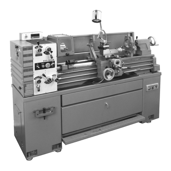
Page 6: Main Features And Nomenclature, Evs-1440B Lathe
4.0 Main features and nomenclature, EVS-1440B Lathe Figure 4-1 1. Headstock 16. Bed ways 2. End cover 17. Tailstock 3. Gearbox 18. Splash guard 4. Chuck key bracket with sensor 19. Steady rest 5. Left stand 20. Cross slide 6. Leveling pad with screw (x6) 21. -
Page 7: Specifications
5.0 Specifications Table 1 Model number EVS-1440B Stock number 311440 Motor and Electricals Type Totally enclosed, fan-cooled, induction Horsepower 3HP (2.2 kW) Phase Main Motor Voltage 230/460V Cycle 60 Hz Listed FLA (full load amps) 8.4/4.2 A Motor speed 1800 RPM... - Page 8 L = length, W = width, H = height The specifications in this manual were current at time of publication, but because of our policy of continuous improvement, JET reserves the right to change specifications at any time and without prior notice, without incurring obligations.
-
Page 9: Machine Dimensions And Hole Spacing
5.1 Machine dimensions and hole spacing Figure 5-1 Figure 5-2... -
Page 10: Setup And Assembly
Read understand assembly instructions before attempting assembly. Failure to comply may cause serious injury. 6.0 Setup and assembly 6.1 Shipping contents See Figure 6-1. 1 Lathe 1 Steady rest (pre-installed) 1 Follow rest (pre-installed) 1 Three jaw scroll chuck 6” (pre-installed) 1 Backplate 6”... -
Page 11: Leveling The Lathe
With proper lifting equipment, slowly raise lathe off shipping pallet. (See Figure 6-2). Do not lift lathe by the spindle. Do not place slings around bed – this can bend leadscrew and feed shaft. Figure 6-3 6.4 Completing installation Exposed metal surfaces have been treated with an anti-corrosion coating. -
Page 12: Break-In Period
Failure to comply may cause serious damage to lathe mechanisms. The JET lathe is shipped with appropriate oil in the reservoirs of headstock, gearbox and apron. Coolant is not included. Use clean lubricants and check levels often, including before each working shift. - Page 13 apron. Drain oil completely and refill after first three months of operation. Then, change oil in the apron annually. Figure 7-2 External Gears – Coat all gears (Figure 7-3) with a heavy, non-slinging grease. Figure 7-4 (cutting tool not provided) Saddle –...
-
Page 14: Coolant Preparation
11. Leadscrew – Lubricate ball oiler (R, Figure 7- 8.0 Electrical connections 6) once daily. Electrical connections must be made by a qualified electrician in compliance with all relevant codes. This machine must be properly grounded while in use to help protect the operator from electrical shock and possible fatal injury. - Page 15 Power Indicator Light (A, Figure 9-1). Illuminates whenever lathe is receiving electrical current. Coolant On-Off Switch (B, Figure 9-1). Activates coolant pump. Jog/Toggle Button (C, Figure 9-1). Quickly press and release to briefly rotate spindle. Emergency Stop Button (D, Figure 9-1). Shuts down all machine functions.
-
Page 16: Operation
16. Top Slide Handwheel (U, Figure 9-2): Rotate 10.0 Operation to position rest. The accompanying scale on collar is graduated in 0.001 inch increments. The operator should consult shop manuals such as “Machinery’s Handbook” for cutting speeds and 17. Tailstock Quill Lock (V, Figure 9-3): Push feeds appropriate to specific workpieces. -
Page 17: Feed And Thread Selection
Figure 10-2 Avoid short clamping contact (A, Figure 10-3) or clamping on a minor part diameter (B, Figure 10-3). Face-locate the workpiece for added support. Figure 10-4 Figure 10-3 10.1 Feed and Thread Selection To obtain various feed settings and thread pitches, the knob and two levers (J, Figure 10-4) are used conjunctively. -
Page 18: Adjustments
Select desired thread using thread pitch levers Loosen two screws with the provided hex key, , Figure 10-4), referring to charts on end remove jaw, and rotate it 180-degrees. Reinstall cover. jaw, and tighten each screw incrementally until fully tightened. Set feed direction lever (P, Figure 10-5) to correct position (neutral). -
Page 19: Tailstock Adjustments
To adjust drag, loosen rear gib screw one turn, and tighten front gib screw a quarter turn. Rotate handwheel to check play. If still loose, tighten front gib screw a bit more. Repeat as needed until slide moves freely without play. When cross slide is properly adjusted, snug rear gib screw. -
Page 20: Aligning Tailstock To Headstock
11.5 Aligning tailstock to headstock Firmly tighten hex nut (L). Set fingers snug to workpiece. Fingers should Headstock and tailstock have been aligned by be snug but not overly tight. the manufacturer and should not require attention. If future adjustment should ever be Loosen three hex nuts (P ), and tighten set needed, proceed as follows. -
Page 21: Gear Change
11.10 Gear change Note: The 120/127, 26, and 52 tooth gears are installed by the manufacturer in the end gear compartment. This combination will cover most inch feeds and threads under normal circumstances. The additional gears found in the toolbox are used for some metric threads and feeds. -
Page 22: Lubrication Schedule
Regularly scheduled maintenance is crucial to ensure a long service life for your machine. The schedule below shows lubrication points and coolant replacement information for the EVS-1440B Lathe. Push stop button and power off before lubricating. Follow local regulations for disposal of used coolant/lubricants. Minimize direct skin contact with lubricants and coolants, and wear eye protection when pouring coolant in case of splash. -
Page 23: Thread And Feed Chart
13.0 Thread and feed chart Table 9... -
Page 24: Recommended Cutting Speeds
14.0 Recommended cutting speeds Table 4 Workpiece material Speed (SFM) Feed (LPR) Aluminum 2021 to 6061 0.002 Brass 0.001 Bronze 0.001 Cast Iron Gray 35 to 125 00015 to 0.004 Ductile 15 to 125 0.001 to 0.004 Malleable 35 to 170 0.0015 to 0.003 Copper 101 to 757... -
Page 25: Replacement Parts
Non-proprietary parts, such as fasteners, can be found at local hardware stores, or may be ordered from JET. Some parts are shown for reference only, and may not be available individually. -
Page 26: Evs-1440B Headstock Assembly - Exploded View Ii
15.1.2 EVS-1440B Headstock Assembly – Exploded View II... -
Page 27: Evs-1440B Headstock Assembly - Exploded View Iii
15.1.3 EVS-1440B Headstock Assembly – Exploded View III... -
Page 28: Evs-1440B Headstock Assembly - Parts List
15.1.4 EVS-1440B Headstock Assembly – Parts List Index No Part No Description Size 1 ....EVS1440B-A01 ..Headstock Casting........... 405Lx235Wx264H ..1 2 ....EBL1236VS-A02 ..Headstock Cover ............. 405Lx235Wx23H ..1 3 ....TS-1503061 ....Socket Head Cap Screw ......... M6x25mm ....13 4 .... - Page 29 Index No Part No Description Size 62 ....EBL1236VS-A62 ..Circlip ..............S-25mm ......3 63 ....BB-6205 ....Bearing ..............No.6205 ......1 64 ....EBL1236VS-A64 ..Shaft ................ Ø30x302L 21x25x5 ..1 65 ....EBL1236VS-A65 ..Circlip ..............S-38mm ......1 66 ....
-
Page 30: Evs-1440B Gearbox Assembly - Exploded View I
15.2.1 EVS-1440B Gearbox Assembly – Exploded View I... -
Page 31: Evs-1440B Gearbox Assembly - Exploded View Ii
15.2.2 EVS-1440B Gearbox Assembly – Exploded View II... -
Page 32: Evs-1440B Gearbox Assembly - Exploded View Iii
15.2.3 EVS-1440B Gearbox Assembly – Exploded View III... -
Page 33: Evs-1440B Gearbox Assembly - Parts List
15.2.4 EVS-1440B Gearbox Assembly – Parts List Index No Part No Description Size 1 ....EBL1236VS-B01 ..Gear Box ....................... 1 2 ....EBL1236VS-B02 ..Gasket For Gearbox ..................1 3 ....EBL1236VS-B03 ..Gear Box Cover ..................... 1 4 .... - Page 34 Index No Part No Description Size 60 ....EBL1236VS-B60 ..Shaft ......................1 61 ....EBL1236VS-B61 ..Gear ................. 2M 25T ......1 62 ....EBL1236VS-B62 ..Gear ................. 2.75M 20T ..... 1 63 ....EBL1236VS-B63 ..Gear ................. 2.25M 20T ..... 1 64 ....
-
Page 35: Evs-1440B Apron Assembly - Exploded View I
15.3.1 EVS-1440B Apron Assembly – Exploded View I... -
Page 36: Evs-1440B Apron Assembly - Exploded View Ii
15.3.2 EVS-1440B Apron Assembly – Exploded View II... -
Page 37: Evs-1440B Apron Assembly - Exploded View Iii
15.3.3 EVS-1440B Apron Assembly – Exploded View III... -
Page 38: Evs-1440B Apron Assembly - Parts List
15.3.4 EVS-1440B Apron Assembly – Parts List Index No Part No Description Size 1 ....EBL1236VS-C01 ..Half Nut ..............8TPI ......1 2 ....EBL1236VS-C02 ..Half Nut Bracket ............105Lx50Wx71h ..... 1 3 ....TS-1503021 ....Socket Head Cap Screw ........M6x10mm ..... 2 .... - Page 39 Index No Part No Description Size 57 ....EBL1236VS-C57 ..Shaft ......................1 58 ....EBL1236VS-C58 ..Gear ....................... 1 59 ....EBL1236VS-C59 ..Gear ....................... 1 60 ....EBL1236VS-C60 ..Worm Gear .............. Ø30xØ14x23L ..... 1 61 ....
-
Page 40: Evs-1440B Carriage Assembly - Exploded View
15.4.1 EVS-1440B Carriage Assembly – Exploded View... -
Page 41: Evs-1440B Carriage Assembly - Parts List
15.4.2 EVS-1440B Carriage Assembly – Parts List Index No Part No Description Size 1 ....E1340VS-D01 ... Wiper ............... PVC ......1 2 ....E1340VS-D02 ... Screw ............... 3/16x3/8 in....14 3 ....E1340VS-D03 ... Nut ................6.5txØ7/8"x14W .... 2 4 .... -
Page 42: Evs-1440B Tool Post Assembly - Exploded View
15.5.1 EVS-1440B Tool Post Assembly – Exploded View... -
Page 43: Evs-1440B Tool Post Assembly - Parts List
15.5.2 EVS-1440B Tool Post Assembly – Parts List Index No Part No Description Size 1 ....EVS1440B-A12 ..Handle ..............dia.22xdia.15 x43L..1 ....EVS1440B-E01A ..Handle Assembly (includes #1,2) ..............1 2 ....EBL1236VS-E02 ..Lever ................ Ø1/2"x107L ....1 3 .... -
Page 44: Evs-1440B Tailstock Assembly - Exploded View
15.6.1 EVS-1440B Tailstock Assembly – Exploded View... -
Page 45: Evs-1440B Tailstock Assembly - Parts List
15.6.2 EVS-1440B Tailstock Assembly – Parts List Index No Part No Description Size 1 ....EBL1236VS-F01 ..Nut ................30L ........ 1 2 ....TS-1502041 ....Socket Head Cap Screw ........M5x16mm ..... 4 3 ....EBL1236VS-F03 ..Screw ............... Ø20.5x179L ....1 .... -
Page 46: Evs-1440B Bed Assembly - Exploded View
15.7.1 EVS-1440B Bed Assembly – Exploded View... -
Page 47: Evs-1440B Bed Assembly - Parts List
15.7.2 EVS-1440B Bed Assembly – Parts List Index No Part No Description Size 1 ....EBL1236VS-G01 ..Gap Section ............. 240x190x70 ....1 2 ....TS-1505051 ....Socket Head Cap Screw ......... M10x35mm ....4 3 ....EBL1236VS-G03 ..Taper Pin ..............Ø4x38mm ..... 2 4 .... -
Page 48: Evs-1440B Cabinet And Panel Assembly - Exploded View
15.8.1 EVS-1440B Cabinet and Panel Assembly – Exploded View... -
Page 49: Evs-1440B Cabinet And Panel Assembly - Parts List
15.8.2 EVS-1440B Cabinet and Panel Assembly – Parts List Index No Part No Description Size 41 ....EVS1440B-G41 ..Splash Guard ............1385x266x509H .... 1 42 ....TS-0254011 ....Screw ............... 1/4x3/8 in ....19 43 ....EBL1236VS-G43 ..Cap Screw .............. 1/4x1-1/4 in ....1 44 .... -
Page 50: Evs-1440B End Gear Assembly - Exploded View
15.9.1 EVS-1440B End Gear Assembly – Exploded View... -
Page 51: Evs-1440B End Gear Assembly - Parts List
15.9.2 EVS-1440B End Gear Assembly – Parts List Index No Part No Description Size 35 ....TS-1503031 ....Socket Head Cap Screw ......... M6x12mm ..... 2 50 ....TS-0561051 ....Nut ................1/2 in ......2 75 ....EBL1236VS-G75 ..Washer ..............Ø25xØ1/4"x3T ....2 76 .... -
Page 52: Evs-1440B Chuck Guard Assembly - Exploded View
15.10.1 EVS-1440B Chuck Guard Assembly – Exploded View 15.10.2 EVS-1440B Chuck Guard Assembly – Parts List Index No Part No Description Size 20 ....TS-1503041 ....Socket Head Cap Screw ......... M6x16mm ..... 2 102 .... EBL1236VS-G102 ..Cam ....................... 1 103 .... -
Page 53: Evs-1440B Coolant Pump Assembly - Exploded View
15.11.1 EVS-1440B Coolant Pump Assembly – Exploded View 15.11.2 EVS-1440B Coolant Pump Assembly – Parts List Index No Part No Description Size 62 ....EBL1236VS-G62 ..Coolant Tank ............310Lx220Wx170H ..1 119 .... EVS1440B-G119 ..Pump..........1/8HP,115/230V,1PH,prewired 230V ..1 120 .... -
Page 54: Evs-1440B Dial Indicator Assembly - Exploded View
15.12.1 EVS-1440B Dial Indicator Assembly – Exploded View 15.12.2 EVS-1440B Dial Indicator Assembly – Parts List Index No Part No Description Size 26 ....EBL1236VS-G26 ..Roll Pin ..............Ø3x20mm ..... 1 127 .... EBL1236VS-G127 ..Plate ......................1 128 .... -
Page 55: Evs-1440B Chuck Assembly - Exploded View
135 .... EBL1236VS-SK6 ..3-Jaw Scroll Chuck ..........6" ........1 136 .... EBL1236VS-G136 ..Backplate ..............6" ........1 137 .... EBL1236VS-G137 ..Stud ................. D1-4 ......3 15.14.1 EVS-1440B Face Plate (OPTIONAL) – Exploded View 15.14.2 EVS-1440B Face Plate (OPTIONAL) – Parts List Index No Part No... -
Page 56: Evs-1440B Four-Position Stop Assembly - Exploded View
15.15.1 EVS-1440B Four-Position Stop Assembly – Exploded View 15.15.2 EVS-1440B Four-Position Stop Assembly – Parts List Index No Part No Description Size 7 ....TS-1503051 ....Socket Head Cap Screw ......... M6x20mm ..... 2 17 ....SB-1/4 ....... Steel Ball ..............1/4 in. dia...... 1 18 .... -
Page 57: Evs-1440B Chuck Key Bracket Assembly - Exploded View
15.16.1 EVS-1440B Chuck Key Bracket Assembly – Exploded View 15.16.2 EVS-1440B Chuck Key Bracket Assembly – Parts List Index No Part No Description Size 1 ....TS-1504111 ....Socket Head Cap Screw ......... M8x55mm ..... 2 2 ....EVS1440B-CKB ..Chuck Key Bracket ..................1... -
Page 58: Evs-1440B Steady Rest Assembly - Exploded View
15.17.1 EVS-1440B Steady Rest Assembly – Exploded View 15.17.2 EVS-1440B Steady Rest Assembly – Parts List Index No Part No Description Size 1 ....E1440VS-FR01 ..Nut ................Ø20xØ24x25L ....3 2 ....TS-1523011 ....Set Screw ..............M6x6mm ....... 3 3 .... -
Page 59: Evs-1440B Follow Rest Assembly - Exploded View
15.18.1 EVS-1440B Follow Rest Assembly – Exploded View 15.18.2 EVS-1440B Follow Rest Assembly – Parts List Index No Part No Description Size 1 ....E1440VS-FR01 ..Nut ................Ø20xØ24x25L ....2 2 ....TS-1523011 ....Set Screw ..............M6x6mm ....... 2 3 .... -
Page 60: 892035 Taper Attachment Assembly (Optional) - Exploded View
15.19.1 #892035 Taper Attachment Assembly (OPTIONAL) – Exploded View... -
Page 61: 892035 Taper Attachment Assembly (Optional) - Parts List
15.19.2 #892035 Taper Attachment Assembly (OPTIONAL) – Parts List Index No Part No Description Size 1 ....E1440VS-J01 .... Thrust No. 51101 ................... 2 2 ....E1440VS-J02 .... Block ................ 52x20x35 ...... 1 3 ....E1440VS-J03 .... Yoke ................ 60x42x41.5 ....1 4 .... -
Page 62: Evs-1440B Control Plate Assembly - Exploded View
15.20.1 EVS-1440B Control Plate Assembly – Exploded View... -
Page 63: Evs-1440B Control Plate Assembly - Parts List
15.20.2 EVS-1440B Control Plate Assembly – Parts List Index No Part No Description Size 3 ....EBL1236VS-H03 ..Plate ......................1 4 ....EBL1236VS-H04 ..Brake Resistance ........... 300W 70 220V ... 1 5 ....EBL1236VS-H05 ..Inverter............VFD022B23A/AC240V/3HP ..1 7 .... -
Page 64: Electrical Connections For Evs-1440B
16.0 Electrical Connections for EVS-1440B... -
Page 67: Warranty And Service
JET sells through distributors only. The specifications listed in JET printed materials and on official JET website are given as general information and are not binding. JET reserves the right to effect at any time, without prior notice, those alterations to parts, fittings, and accessory equipment which they may deem necessary for any reason whatsoever. - Page 68 427 New Sanford Road LaVergne, Tennessee 37086 Phone: 800-274-6848 www.jettools.com...
Need help?
Do you have a question about the EVS-1440B and is the answer not in the manual?
Questions and answers