Table of Contents

Related Manuals for Panasonic KX-DT543-B


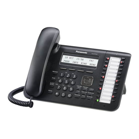
Summary of Contents for Panasonic KX-DT543-B
- Page 1 ORDER NO. KMS1403012CE Digital Proprietary Telephone KX-DT543 Model No. KX-DT543-B KX-DT546 KX-DT546-B White Version Black Version (for USA, Canada) © Panasonic System Networks Co., Ltd. 2014 Unauthorized copying and distribution is a violation of law.
-
Page 2: Table Of Contents
KX-DT543/KX-DT543-B/KX-DT546/KX-DT546-B TABLE OF CONTENTS PAGE PAGE 1 Safety Precautions -----------------------------------------------3 10.2.1. Preparation ------------------------------------------- 42 1.1. For Service Technicians ---------------------------------3 10.2.2. Removal Procedure -------------------------------- 42 2 Warning --------------------------------------------------------------4 10.2.3. Procedure--------------------------------------------- 42 2.1. About Lead Free Solder (PbF: Pb free) --------------4 10.2.4. Removing Solder From Between Pins--------- 42 2.1.1. -
Page 3: Safety Precautions
KX-DT543/KX-DT543-B/KX-DT546/KX-DT546-B 1 Safety Precautions 1. Before servicing, unplug the AC power cord to prevent an electric shock. 2. When replacing parts, use only the manufacturer's recommended components. 3. Check the condition of the power cord. Replace if wear or damage is evident. -
Page 4: Warning
KX-DT543/KX-DT543-B/KX-DT546/KX-DT546-B 2 Warning 2.1. About Lead Free Solder (PbF: Pb free) Note: In the information below, Pb, the symbol for lead in the periodic table of elements, will refer to standard solder or solder that contains lead. We will use PbF solder when discussing the lead free solder used in our manufacturing process which is made from Tin (Sn), Silver (Ag), and Copper (Cu). -
Page 5: Specifications
KX-DT543/KX-DT543-B/KX-DT546/KX-DT546-B 3 Specifications... -
Page 6: Technical Descriptions
KX-DT543/KX-DT543-B/KX-DT546/KX-DT546-B 4 Technical Descriptions 4.1. Block Diagram... -
Page 7: Circuit Operations
KX-DT543/KX-DT543-B/KX-DT546/KX-DT546-B 4.2. Circuit Operations 4.2.1. LCD Circuit LCD data are output from pin 66 of IC410 to LCD module. LCD contrast is set by electronic volume in LCD module. VCC33 (+3.3V) of the power supply voltage is pressurized about four/three times in the LCD module and used as LCD driving volt- age (approx. -
Page 8: Data Communication
KX-DT543/KX-DT543-B/KX-DT546/KX-DT546-B 4.2.3. Data Communication Function The data communication circuit serves the following functions: Information exchanger between PBX and proprietary telephone, key input information as well as data for the LED control, LCD control, voice data, etc. This information is continuously exchanged at all times. -
Page 9: Dxdp Communication
KX-DT543/KX-DT543-B/KX-DT546/KX-DT546-B 4.2.4. DXDP Communication Function: This circuit performs the same type of communication as between the DPT and PBX, but a slave DPT for DXDP is connected to the DXDP port. In addition, it controls power feeding for a slave DPT. -
Page 10: Analog Circuit
KX-DT543/KX-DT543-B/KX-DT546/KX-DT546-B 4.2.5. Analog Circuit 1. Speaker phone call Transmitting signal is input from microphone input to IC410-pin 33 and 34 amplified by a built-in analog amplifier of IC410 A/D conversion, Gain adjustment and echo cancel by a built-in DSP of IC410. -
Page 11: Asic (Ic300)
KX-DT543/KX-DT543-B/KX-DT546/KX-DT546-B 3. Headset Call Transmitting signal is input from headset microphone input to IC410-pin 26 amplified by a built-in analog amplifier of IC410 A/D conversion, Gain adjustment and echo cancel by a built-in DSP of IC410. Receiving signal is sent by data from PBX Gain adjustment and D/A conversion by a built-in DSP of IC410 amplified by a built-in analog amplifier of IC410 ... -
Page 12: Asic (Ic150)
KX-DT543/KX-DT543-B/KX-DT546/KX-DT546-B 4.2.7. ASIC (IC150) IC150 controls KEY, LED, EHS and Headset-detect. An operation clock is provided from IC300. IC410 controls reset signal (L(0V): Reset) for IC150. IC150 and IC410 are connected via I2C interface. IC410 checks the presence of IC150 by getting the signal from IC150. -
Page 13: Key Circuit
KX-DT543/KX-DT543-B/KX-DT546/KX-DT546-B 4.2.8. Key Circuit The key detection is under the matrix control by IC150. The HOOK key is independent from Key Scan Matrix and taken into the port singularly. KEY Input control timing chart KEYIN pins have a internal pull-down resistor. -
Page 14: Led Circuit
KX-DT543/KX-DT543-B/KX-DT546/KX-DT546-B 4.2.9. LED Circuit The lighting of the LEDs is controlled by IC150. Ringer LEDs are static lighting system. Other LEDs light up in a dynamic lighting system. The duty ratio is 1/10 (ON time 1.28ms). -
Page 15: Ehs Circuit
KX-DT543/KX-DT543-B/KX-DT546/KX-DT546-B LED dynamic control timing chart LED lights with 3.3V created by the STB pin of the High output and Transistor Collector pin of the Low output. 12.6ms 0.1ms 1.28ms LED_STB2 Q110C CO3(Red) lighting Q111C CO5(Red) lighting Q112C CO10(Red) lighting... -
Page 16: Power Supply Circuit
KX-DT543/KX-DT543-B/KX-DT546/KX-DT546-B 4.2.11. Power Supply Circuit... -
Page 17: Location Of Controls And Components
KX-DT543/KX-DT543-B/KX-DT546/KX-DT546-B 5 Location of Controls and Components 5.1. Name and Locations Front View... -
Page 18: Installation Instructions
Connections Note • When connecting a headset The following headsets can be used with this unit. (Not all operations with the headsets can be guaranteed.) - Wired headsets Panasonic RP-TCA400 or KX-TCA430 - EHS headsets ® Selected Plantronics -brand headsets For up-to-date information about headsets that have been tested with this unit, please contact your dealer. -
Page 19: Test Mode
KX-DT543/KX-DT543-B/KX-DT546/KX-DT546-B 7 Test Mode 7.1. Function Test Mode 7.1.1. Preparation Preparation device • Unit for Test phone • PBX (including DLC or DHLC) Set up unit in test mode by key control 1. Connect DLC or DHLC (power on) while pressing "1","*" and "CONF" keys at the same time. -
Page 20: Troubleshooting Guide
KX-DT543/KX-DT543-B/KX-DT546/KX-DT546-B 8 Troubleshooting Guide 8.1. No Operation [ Power supply circuit ] Remove L221(VDD33), L220(VCCA33) and L222(VCC33) from Main PCB. Disconnect Operation PCB from Main PCB. Connect DPT to PBX. Check the soldering. Resolder or replace parts as needed. Confirm the voltage between Pin + and Pin - of Related parts: JK300,L301,L302,T300,D300, C550. - Page 21 KX-DT543/KX-DT543-B/KX-DT546/KX-DT546-B [ DCX81(IC410) ] Boot ROM Error into IC410 (No.2) Check the TEST POINT(ST0-ST3). See Table-1. See Table-2 (P.23). Is it "NOT Error (No.1)" ? [ Flash ROM(IC401) ] Flash ROM(IC401) Data Error / DSP Data Error (No.3,4,6,7) See Table-3 (P.24).
- Page 22 KX-DT543/KX-DT543-B/KX-DT546/KX-DT546-B Table-1: PORT OUTPUT at ERROR The error result is output to a port of IC410 at error. Check the Test Point ST3,ST2,ST1 and ST0. See below for the output contents. Test Point Error Item Related Points LCD Error Message.
- Page 23 KX-DT543/KX-DT543-B/KX-DT546/KX-DT546-B Table-2 : Boot ROM Error IC410 Check the soldering. Resolder or replace parts as needed. Confirm the voltage at Pin 19 of IC410 (VCC33). Related parts: L222 Is it about 3.3V? Related parts: L410,C413,C406,C407, Confirm the voltage at TP:1.2V.
- Page 24 KX-DT543/KX-DT543-B/KX-DT546/KX-DT546-B Table-3 : Flash ROM(IC401) Data Error / DSP Data Error Check the soldering. Resolder or replace parts as needed. Confirm the voltage at Pin 8 of IC401 (VCC33) and Pin 106 of IC410. Related parts: C400,C559,IC401,IC410,L222 Are they about 3.3V? Confirm the frequency of clock signal at Pin 6 of IC401.
- Page 25 KX-DT543/KX-DT543-B/KX-DT546/KX-DT546-B Table-4 : ASIC2(IC150) Data Error Check the soldering. Resolder or replace parts as needed. Related parts: [Main PCB] CN400 Confirm the voltage at Pin 3 of IC150 (Ope PCB). [Ope PCB] CN160,D160,C160,C161,C154 Is it about 3.3V? C156 Flat Cable (Between Main PCB and Ope PCB)
-
Page 26: Asic1(Ic300) Does Not Operate
KX-DT543/KX-DT543-B/KX-DT546/KX-DT546-B 8.2. ASIC1(IC300) Does Not Operate Check the soldering. Resolder or replace parts as needed. Confirm the voltage at Pin19,30 and 43 of Related parts: C323,C327,C324,C328,C326, IC300 (VCC33). C329, L222 Is it about 3.3V? Confirm the frequency of clock signal at Pin 39 of IC300. -
Page 27: Lcd Does Not Operate
KX-DT543/KX-DT543-B/KX-DT546/KX-DT546-B 8.3. LCD Does Not Operate Check the soldering. Resolder or replace parts as needed. Confirm the voltage at Pin7 of CN460. Related parts: CN460,D460,C460-462,C464 Is it about 3.3V? Confirm the voltage between Pin 12 and Pin 13 of CN460. -
Page 28: Dxdp Does Not Work
KX-DT543/KX-DT543-B/KX-DT546/KX-DT546-B 8.4. DXDP Does Not Work Connect DPT to DXDP port. Check the soldering. Resolder or replace parts as needed. Confirm the voltage at Pin 4 of Q332 (VDD33). Related parts: L221 Is it about 3.3V? Related parts: Q330,R345,R346,R347,C331, Confirm the voltage between TP:H-D and TP:L-D. -
Page 29: Audio Problem
KX-DT543/KX-DT543-B/KX-DT546/KX-DT546-B 8.5. Audio Problem Check the soldering. Resolder or replace parts as needed. Confirm the voltage at Pin 31 and Pin 39 of Related parts: R427,C418,C419,C421,C455, IC410 (VCCA33). R557,C420,C453,L220 Is it about 3.3V? Handset problem ? See 8.6 Headset problem ? See 8.7... -
Page 30: Send
KX-DT543/KX-DT543-B/KX-DT546/KX-DT546-B 8.6.2. Send Check the soldering. Resolder or replace parts as needed. Confirm the voltage between Pin 6 of IC150 and AG. Related parts: IC150,R161,L163,D163,JK160 Is it about 2.3V? Confirm the voltage between either end of C443 (MICBIAS). Related parts: IC410,C442,R238,C443 Is it about 2.5V? -
Page 31: Headset Does Not Work
KX-DT543/KX-DT543-B/KX-DT546/KX-DT546-B 8.7. Headset Does Not Work 8.7.1. Receive Check the soldering. Resolder or replace parts as needed. Insert a headset Confirm the waveform of dial tone at Related parts: IC410,C577,L462 TP:HESSPOUT when you press the speaker button. Can you see the waveform of dial tone? -
Page 32: Send
KX-DT543/KX-DT543-B/KX-DT546/KX-DT546-B 8.7.2. Send Insert a headset Check the soldering. Resolder or replace parts as needed. Confirm the voltage between either end of C443 (MICBIAS). Related parts: IC410,C442,R238,C443 Is it about 2.5V? Related parts: Confirm the voltage between TP:HESMIN and [Main PCB] CN400,L461,C576,R566,R569, TP:UART_GND. -
Page 33: Speaker-Phone/Ringer Does Not Work
KX-DT543/KX-DT543-B/KX-DT546/KX-DT546-B 8.8. Speaker-Phone/Ringer Does Not Work 8.8.1. Receive / Ringer Check the soldering. Resolder or replace parts as needed. Confirm the waveform of dial tone between TP:SPP Related parts: IC410,C500,C501,R501,R502, and TP:SPN, when you press the speaker button. (Speaker-phone mode). -
Page 34: Led Does Not Light
KX-DT543/KX-DT543-B/KX-DT546/KX-DT546-B 8.9. LED Does Not Light Check the soldering. Resolder or replace parts as needed. Does SP-PHONE_LED light? Related parts: IC150,D139,R101,R111,Q117, cR200, and Jumper hip Does RINGER LED(RED) light? Related parts: IC150,R108,D109, and Jumper chip Related parts: IIC150,R109,D108,Q104,R110, Does RINGER LED(GREEN) light? -
Page 35: Ehs Does Not Work
KX-DT543/KX-DT543-B/KX-DT546/KX-DT546-B 8.10. EHS Does Not Work 8.10.1. EHS (Plantronics) Does Not Work Check the soldering. Resolder or replace parts as needed. Mesure the EHSDET voltage at Pin 7 of IC150. Related parts: R181,IC171,R177,Q170,R175, Is it 0V? D171,D172,JK302, and Jumper chip... -
Page 36: Ehs (Jabra) Does Not Work
KX-DT543/KX-DT543-B/KX-DT546/KX-DT546-B 8.10.2. EHS (Jabra) Does Not Work Check the soldering. Resolder or replace parts as needed. Mesure the EHSDET voltage at Pin 7 of IC150. Related parts: R181,IC171,R177,Q170,R175, Is it 0V? D171,D172,JK302, and Jumper chip Measure the JABRA_UTX signal between Pin 1 Related parts: [Main PCB] R453,R433,IC410 Pin 4 of JK302. -
Page 37: Disassembly And Assembly Instructions
KX-DT543/KX-DT543-B/KX-DT546/KX-DT546-B 9 Disassembly and Assembly Instructions 9.1. Remove Main Board and Ope Board 1. Remove the Stand. 2. Remove 7 Screws (A). 3. Remove the Lower Cabinet. 4. Remove 4 Screws (A). 5. Remove 2 Flat Cables and Connector. -
Page 38: Remove And Assembly For Lcd
KX-DT543/KX-DT543-B/KX-DT546/KX-DT546-B 6. Remove 2 Screws (A). 7. Remove the Main Board. 8. Remove 2 Screws (A). 9. Remove the PCB Holder. 10. Remove 5 Screws (A). 11. Remove the Ope Board. 9.2. Remove and Assembly for LCD Please note the tab when LCD is resolved and assembled. -
Page 39: Assembly For Lead Wire
KX-DT543/KX-DT543-B/KX-DT546/KX-DT546-B 9.3. Assembly for Lead wire Perform this process in reverse when taking the unit apart. **LEAD WIEW STYLING** WIRE (ORANGE) WIRE (BLUE) PCB HOLDER **LFW-SOLDER、 PART STICKING** The connector is surely inserted up to the White modle only A : Confirm that LEAD WIRE does not root and locked. - Page 40 KX-DT543/KX-DT543-B/KX-DT546/KX-DT546-B Note: Cable is to be inserted into connector CN460,CN400,CN160 without any inclining, as shown. <NG> <OK>...
-
Page 41: Miscellaneous
KX-DT543/KX-DT543-B/KX-DT546/KX-DT546-B 10 Miscellaneous 10.1. Terminal Guide of the ICs Transistors and Diodes 10.1.1. Main Board 10.1.2. Operation Board... -
Page 42: How To Replace A Flat Package Ic
KX-DT543/KX-DT543-B/KX-DT546/KX-DT546-B 10.2. How To Replace a Flat Package IC Even if you do not have the special tools (for example, a spot heater) to remove the Flat IC, with some solder (large amount), a sol- dering iron and a cutter knife, you can easily remove the ICs that have more than 100 pins. -
Page 43: Memo
KX-DT543/KX-DT543-B/KX-DT546/KX-DT546-B 10.2.5. Memo... -
Page 44: Schematic Diagram
KX-DT543/KX-DT543-B/KX-DT546/KX-DT546-B 11 Schematic Diagram 11.1. Main No.1 (9) IC300(ASIC1) -IC410(DCX81) signal (SPI2) (10) IC300(ASIC1) - IC410(DCX81) signal (PCM) (8) IC300(ASIC1) - IC410(DCX81) signal (Reset) RESET VCC33 (11) DPT - PBX signal (Receiving signals) R334 13 CK4M CK4M DDX1 14 VSS2... - Page 45 KX-DT543/KX-DT543-B/KX-DT546/KX-DT546-B (12) DPT - PBX signal (Transmitting signals) (11) DPT - PBX signal (Receiving signals) (12) DPT - PBX signal (Transmitting signals) 1000p 50 C308 1000p C305 C303 1u 10 R305 1.8k 1608 50V 1u T300 R302 JK300 VDD33 D300...
-
Page 46: Main No.2
KX-DT543/KX-DT543-B/KX-DT546/KX-DT546-B 11.2. Main No.2 (14) LCD - IC410(DCX81) signal (Reset) C460 (3) IC401(Flash) - IC410(DCX81) signal (Communication) C461 SPI_DO (2) Clock (IC401:Flash) 103.68MHz SPI_CS0 LCD_RST LCD_RST GPIO15 LCD_A0 VCC33 SPI_CLK (15) LCD - IC410(DCX81) signal (Communication) C400 0.1u (13) Clock (LCD) SPI_CLK... - Page 47 KX-DT543/KX-DT543-B/KX-DT546/KX-DT546-B LCD + Backlit VCC33 LCD_PWR VCCA33 TP_LED+ LED+ TP_LED- LED- SIGN2741 Q460 LCD_BL R501 R502 MICBIAS C569 AGND R530 R532 MIC1 MICP 3.3k C540 0.1u AGND AGND AGND R531 R533 MICN MIC2 3.3k C541 0.1u AGND AGND AGND AGND...
-
Page 48: Ope
KX-DT543/KX-DT543-B/KX-DT546/KX-DT546-B 11.3. Ope (6) IC150(ASIC2) - IC410(DCX81) signal (Reset) (5) Clock (IC150:ASIC2) 2MHz (7) IC150(ASIC2) - IC410(DCX81) signal (Communication) (10) (11) (12) (13) (21) JABRA_URX signal (14) (15) (16) (17) (18) (19) (20) JABRA_UTX signal (19) EHSRX signal (18) EHSTX signal... - Page 49 KX-DT543/KX-DT543-B/KX-DT546/KX-DT546-B (10) (11) (12) (13) (14) (15) (16) (17) (18) (19) KX-DT543/KX-DT546 OPERATION BOARD (2/2)
-
Page 50: Waveform
KX-DT543/KX-DT543-B/KX-DT546/KX-DT546-B 11.4. Waveform 11.4.1. No.(1)-(6) (1) Clock (IC410:DCX81) 13.824MHz (2) Clock (IC401:Flash) 103.68MHz 45pin(XOUT) 6pin of IC401 of IC410 (3) IC401(Flash) - IC410(DCX81) signal (Communication) (4) Clock (IC300:ASIC1) 16.384MHz 1pin(*CS) of IC401 39pin(OSO) of IC300 6pin(CLK) of IC401 5pin(IO0) of IC401... -
Page 51: No.(7)-(10)
KX-DT543/KX-DT543-B/KX-DT546/KX-DT546-B 11.4.2. No.(7)-(10) (7) IC150(ASIC2) - IC410(DCX81) signal (Communication) 43pin(I2C_SCL) 43pin(I2C_SCL) IC150 IC150 44pin(I2C_SDA) 44pin(I2C_SDA) IC150 IC150 (8) IC300(ASIC1) - IC410(DCX81) signal (Reset) (9) IC300(ASIC1) - IC410(DCX81) signal (SPI2) SPI2_CLK SPI2_CS VCC33 SPI2_DO 1pin(RESET) SPI2_DI of IC300 (10) IC300(ASIC1) - IC410(DCX81) signal (PCM) -
Page 52: No.(11)-(12)
KX-DT543/KX-DT543-B/KX-DT546/KX-DT546-B 11.4.3. No.(11)-(12) (11) DPT - PBX signal (Receiving signals) 28pin(PVRH) of IC300 27pin(PDR) of IC300 Between "H" and "L" 26pin(PVRL) of IC300 Receiving signals from PBX (12) DPT - PBX signal (Transmitting signals) 32pin(PDX1) of IC300 Between "H" and "L"... -
Page 53: No.(13)-(15)
KX-DT543/KX-DT543-B/KX-DT546/KX-DT546-B 11.4.4. No.(13)-(15) (13) Clock (LCD) SPI_CLK SPI_CLK SPI_CLK (14) LCD - IC410(DCX81) signal (Reset) VCC33 LCD_RST (15) LCD - IC410(DCX81) signal (Communication) SPI_CLK SPI_CLK SPI_CS0 SPI_CS0 LCD_A0 LCD_A0 SPI_D0 SPI_D0... -
Page 54: No.(16)-(17)
KX-DT543/KX-DT543-B/KX-DT546/KX-DT546-B 11.4.5. No.(16)-(17) (16) DXDP signal (Receiving signals) 23pin(DVRH) of IC300 22pin(DDR) Between "HD" and "LD" of IC300 21pin(DVRL) of IC300 Receiving signals from DXDP (17) DXDP signal (Transmitting signals) 47pin(DDX0) of IC300 Between "HD" and "LD" 3pin of Q332... -
Page 55: No.(18)-(21)
KX-DT543/KX-DT543-B/KX-DT546/KX-DT546-B 11.4.6. No.(18)-(21) (18) EHSTX signal (19) EHSRX signal 8pin(EHS_RX) of IC150 Between 3pin and 4pin of JK302 (20) JABRA_UTX signal Between 1pin and 4pin of JK302 (21) JABRA_URX signal 10pin of IC410 10pin(JABRA_URX) on Main PCB of CN160... -
Page 56: Memo
KX-DT543/KX-DT543-B/KX-DT546/KX-DT546-B 11.4.7. Memo... -
Page 57: Printed Circuit Board
KX-DT543/KX-DT543-B/KX-DT546/KX-DT546-B 12 Printed Circuit Board 12.1. Main Board 12.1.1. Component View C 5 1 6 cam1 C 4 4 3 C 5 1 5 R 2 3 8 C 5 3 1 C 5 1 7 C 5 3 2... -
Page 58: Bottom View
KX-DT543/KX-DT543-B/KX-DT546/KX-DT546-B 12.1.2. Bottom View C 5 6 3 C 4 1 9 R 5 5 9 C 4 1 8 S P N R 5 7 0 C 5 7 2 S P P C 4 2 7 H S M I P... -
Page 59: Operation Board
KX-DT543/KX-DT543-B/KX-DT546/KX-DT546-B 12.2. Operation Board 12.2.1. Component View R179 R170 C170 D171 R171 C171 D170 D172 R172 R175 C169 R173 C168 Q170 C159 J262 IC172 R176 C158 C172 R161 R181 R178 J281 Q174 R202 IC173 R160 J275 SW60 J276 Q173 J272... -
Page 60: Mic Board Component View
KX-DT543/KX-DT543-B/KX-DT546/KX-DT546-B 12.2.2. MIC Board Component View MIC+ MIC- BOARD COMPONENT VIEW... -
Page 61: Appendix Information Of Schematic Diagram
KX-DT543/KX-DT543-B/KX-DT546/KX-DT546-B 13 Appendix Information of Schematic Diagram Note: 1. DC voltage measurements are taken with an oscilloscope or a tester with a ground. 1. The schematic diagrams and circuit board may be modified at any time with the development of new technology. -
Page 62: Exploded View And Replacement Parts List
KX-DT543/KX-DT543-B/KX-DT546/KX-DT546-B 14 Exploded View and Replacement Parts List 14.1. IC Data 14.1.1. IC410 28 DCIN2 QSCLK 29 DCIN3/LIN1 30 LEDSINK1/PWM1 QVCC 31 VREF 32 VCCA QCSN0 33 MIN QCSN1/EXGPIO0 34 MIP GPIO25/XD4 35 HSMIN GPIO24/XD5 36 HSMIP GPIO23/XD6 37 MPWR... - Page 63 KX-DT543/KX-DT543-B/KX-DT546/KX-DT546-B Pin No. Terminal Name Function I/O Setting Contents of Control Remarks HSMIN HSMICINN Handset Mic negative input HSMIP HSMICINP Handset Mic positive input MPWR (MICBIAS) Mic power output Pull-up to MICBIAS at 390Ω SPOUTP Hands free Speaker positive output...
- Page 64 KX-DT543/KX-DT543-B/KX-DT546/KX-DT546-B Pin No. Terminal Name Function I/O Setting Contents of Control Remarks GPIO18 (SPI_CLK) LCD Serial clock LCD control port GPIO19 (SPI_CS0) LCD Chip select LCD control port GPIO20 Not in use GPIO22 Not in use GPIO23 Receive data from Jabra / Software down-...
-
Page 65: Ic300
KX-DT543/KX-DT543-B/KX-DT546/KX-DT546-B 14.1.2. IC300 25 GPIO4 SPICS 26 PVRL SPICLK 27 PDR SPIRX 28 PVRH SPITX 29 NC2 30 VDD2 OCLK IC300 31 VSS4 VSS1 32 PDX1 OSYNC 33 PDX0 OEP1 34 GPIO5 OEP0 35 GPIO6 36 GPIO7 RSTN Pin No. Terminal Name... -
Page 66: Ic150
KX-DT543/KX-DT543-B/KX-DT546/KX-DT546-B IC150 14.1.3. Pin No. Terminal Name Function I/O Setting Contents of Control Remarks CLKIN CK4M System clock input from IC300 (2MHz) CLKOUT GIN08 HOOK Switch Input VDD1 3.3V Digital system power supply (+3.3V) VSS1 Digital system ground Not in use... -
Page 67: Cabinet And Electric Parts
KX-DT543/KX-DT543-B/KX-DT546/KX-DT546-B 14.2. Cabinet and Electric Parts KX-DT546 PCB2-b PCB2-a SCREWS Figure Ref. No. PCB1 ( 2.6 10 mm) KX-DT543... -
Page 68: Accessories And Packing Materials
KX-DT543/KX-DT543-B/KX-DT546/KX-DT546-B 14.3. Accessories and Packing Materials KX-DT546... -
Page 69: Replacement Parts List
KX-DT543/KX-DT543-B/KX-DT546/KX-DT546-B 14.4. Replacement Parts List 1. RTL (Retention Time Limited) Safety Ref. Part No. Part Name & Description Remarks Note: PNBH1012Z2 HOOK BUTTON(WHITE) The “RTL” marking indicates that its Retention Time is PNUS1126Z SPRING HOOK BUTTON Limited. PNBC1500Y1 CURSOR KEY(WHITE) -
Page 70: Accessories And Packing Materials
KX-DT543/KX-DT543-B/KX-DT546/KX-DT546-B Safety Ref. Part No. Part Name & Description Remarks Safety Ref. Part No. Part Name & Description Remarks PNBX1104Z2 CO KEY RIGHT_WHITE IC401 There is no parts supply of PNBX1110Z1 CO KEY LEFT_BLACK only IC. Please order PCB1. PNBX1110Z2... - Page 71 KX-DT543/KX-DT543-B/KX-DT546/KX-DT546-B Safety Ref. Part No. Part Name & Description Remarks Safety Ref. Part No. Part Name & Description Remarks C416 ECUE1A104KBQ C581 ECUE1H102KBQ 0.001 C418 ECUE1C104KBQ C419 ECUE1C104KBQ (RESISTORS) C420 ECUE1C104KBQ L220 ERJ3GEY0R00 C421 F1J0J2260002 L221 ERJ3GEY0R00 C422 ECUE1A104KBQ L222...
-
Page 72: Ope Board Parts
KX-DT543/KX-DT543-B/KX-DT546/KX-DT546-B Safety Ref. Part No. Part Name & Description Remarks Safety Ref. Part No. Part Name & Description Remarks R437 ERJ2GE0R00 (CRYSTAL OSCILLATOR) R438 ERJ2GEJ102 X301 H0J163500033 CRYSTAL OSCILLATOR R439 ERJ2GEJ271 X410 H0J138500003 CRYSTAL OSCILLATOR R440 ERJ2GEJ271 R441 ERJ2GEJ471 14.4.4. Ope Board Parts... - Page 73 KX-DT543/KX-DT543-B/KX-DT546/KX-DT546-B Safety Ref. Part No. Part Name & Description Remarks Safety Ref. Part No. Part Name & Description Remarks D139 PSVD1SRCT DIODE(SI) J238 ERJ8GEY0R00 D140 B3AGB0000050 DIODE(SI) J239 ERJ8GEY0R00 D170 DZ2J068M0L DIODE(SI) J240 ERJ8GEY0R00 D172 DZ2J056M0L DIODE(SI) J241 ERJ8GEY0R00 J242...
- Page 74 KX-DT543/KX-DT543-B/KX-DT546/KX-DT546-B Safety Ref. Part No. Part Name & Description Remarks R183 ERJ2GE0R00 R184 ERJ2GE0R00 R185 ERJ2GEJ151 R186 ERJ3GEYJ102 R188 ERJ3GEYJ102 R190 ERJ3GEYJ102 R192 ERJ3GEYJ102 R194 ERJ3GEYJ102 R196 ERJ3GEYJ102 R198 ERJ3GEYJ102 R200 ERJ3GEYJ102 R202 ERJ2GEJ222 2.2k R203 ERJ2GE0R00 (FILTERS AND COILS)
Need help?
Do you have a question about the KX-DT543-B and is the answer not in the manual?
Questions and answers