Table of Contents
Advertisement
Quick Links
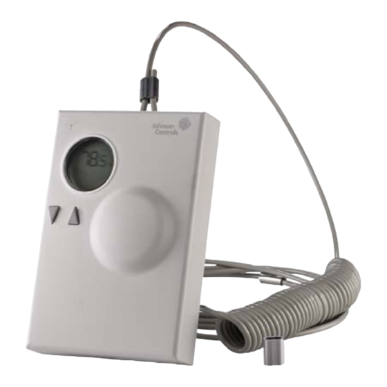
WRZ-TTB0000-5 Handheld Temperature Room Sensor
Installation Guide
WRZ-TTB0000-5
Application
The WRZ Handheld Temperature Room Sensor is
designed to sense the temperature of a room or zone
and transmit wireless temperature control data.
In a mesh application, the WRZ sensor is compatible
with both the ZFR1810 and ZFR1820 Pro Series
Wireless Field Bus Systems. The sensors
communicate with FAC26 Series, FEC16 Series,
FEC26 Series, and VMA16 Series Controllers through
the ZFR18xx Router (ZFR or ZFR Pro Series Router).
Up to nine WRZ Series Sensors can be associated
with a single Controller.
In wired field bus applications, the sensors
communicate with a WRZ-78xx Wireless Receiver. The
WRZ-78xx Receiver transfers data to the controller by
means of the Sensor Actuator (SA) communication
bus. In a typical application, one WRZ Series Sensor
reports to one WRZ-78xx Receiver, but up to five
WRZ Series Sensors can be associated with a single
WRZ-78xx Receiver for multi-sensor averaging or
high/low temperature selection.
The WRZ Handheld Temperature Room Sensor comes
with an LCD. The WRZ Sensor can transmit sensed
temperature, setpoint temperature, occupancy status,
and low battery conditions to an associated router or
receiver. The WRZ Sensor is designed for indoor,
intra-building applications only.
Refer to the
QuickLIT website
The WRZ Sensor uses direct-sequence,
spread-spectrum RF technology, and operates on the
2.4 GHz industrial, scientific, and medical (ISM) band.
The receiver meets the IEEE 802.15.4 standard for low
power, low duty cycle RF transmitting systems.
WRZ-TTB0000-5 Handheld Temperature Room Sensor Installation Guide
*24107240D*
(barcode for factory use only)
Part No. 24-10724-0, Rev. D
for the most up-to-date version of this document.
IMPORTANT: The WRZ Sensor is intended to
provide an input to equipment under normal
operating conditions. Where failure or malfunction of
the sensor could lead to personal injury or property
damage to the controlled equipment or other
property, additional precautions must be designed
into the control system. Incorporate and maintain
other devices, such as supervisory or alarm systems
or safety or limit controls, intended to warn of or
protect against failure or malfunction of the sensor.
IMPORTANT : Le WRZ Sensor est destiné à
transmettre des données entrantes à un équipement
dans des conditions normales de fonctionnement.
Lorsqu'une défaillance ou un dysfonctionnement du
sensor risque de provoquer des blessures ou
d'endommager l'équipement contrôlé ou un autre
équipement, la conception du système de contrôle
doit intégrer des dispositifs de protection
supplémentaires. Veiller dans ce cas à intégrer de
façon permanente d'autres dispositifs, tels que des
systèmes de supervision ou d'alarme, ou des
dispositifs de sécurité ou de limitation, ayant une
fonction d'avertissement ou de protection en cas de
défaillance ou de dysfonctionnement du sensor.
24-10724-0, Rev. D
Issued March 2019
1
Advertisement
Table of Contents

Subscribe to Our Youtube Channel
Related Manuals for Johnson Controls WRZ-TTB0000-5


Summary of Contents for Johnson Controls WRZ-TTB0000-5
- Page 1 The WRZ Sensor is designed for indoor, dispositifs de sécurité ou de limitation, ayant une intra-building applications only. fonction d'avertissement ou de protection en cas de défaillance ou de dysfonctionnement du sensor. WRZ-TTB0000-5 Handheld Temperature Room Sensor Installation Guide...
-
Page 2: North American Emissions Compliance
• wire cutter to cut the tether cable Parts Included • Phillips screwdriver for accessing battery holder • one WRZ Handheld Temperature Room Sensor • tether cable with aluminum sleeves WRZ-TTB0000-5 Handheld Temperature Room Sensor Installation Guide... - Page 3 ZFR or ZFR Pro Series Router is 50 ft (15 m). Figure 3: Cutting the Cable 2. Remove the temperature sensor cover from its base by loosening the set screw. See Figure 1. 3. Remove the temperature sensor housing from its mounting base. WRZ-TTB0000-5 Handheld Temperature Room Sensor Installation Guide...
- Page 4 10. Use a 1/16 in. (1.6 mm) Allen wrench or a Johnson Controls T-4000-119 Allen-Head Adjustment Tool to tighten the tamper-resistant set screw and secure the temperature sensor assembly onto its mounting base. WRZ-TTB0000-5 Handheld Temperature Room Sensor Installation Guide...
- Page 5 Actual installation of the tether cord style to securely cradle the temperature room sensor. varies based on room parameters, but we recommend using a security anchor from a Johnson Controls approved vendor such as Tufnut (www.tufnut.com). Tufnut also offers anchor plates as well as security screws that can be used to secure a looped and crimped end of the tethered cord.
- Page 6 ZFR or ZFR Pro Series Coordinator, ZFR or ZFR Pro Series Router, and WRZ Handheld Sensor in a mesh network. See Figure 11: One-to-One Network Application Figure 13. DIP Switch Overlay WRZ-TTB0000-5 Handheld Temperature Room Sensor Installation Guide...
-
Page 7: Zone Number
Table 1: Setting the ZONE DIP Switches Zone Number SA Bus Address Insert two AA alkaline AA Alkaline Battery batteries in battery compartment. Figure 14: Battery Placement 6. Tighten the battery compartment cover into place. WRZ-TTB0000-5 Handheld Temperature Room Sensor Installation Guide... -
Page 8: Signal Strength
To force the WRZ Series Sensor into rapid transmit mode, press and hold the manual occupancy override (Occ) button on a WRZ Series Sensor for 5 or more seconds. WRZ-TTB0000-5 Handheld Temperature Room Sensor Installation Guide... -
Page 9: Address Setting
Sensors per field controller. You can use any nine of the sixteen available Zone Netsensor address settings The one-to-one mode of operation is intended for use at a time. with the WRZ-78xx Receiver. For one-to-one mode, Figure 11 shows DIP switch settings. WRZ-TTB0000-5 Handheld Temperature Room Sensor Installation Guide... -
Page 10: Repair Information
Sensor, to Function as a Site Survey Tool for the WRZ-78xx-0 One-to-One Room Temperature Sensing System, or for the ZFR or ZFR Pro Wireless Field Bus System T-4000-119 Allen-Head Adjustment Tool: 1/16 in. (1.6 mm), 30 Tools per Bag WRZ-TTB0000-5 Handheld Temperature Room Sensor Installation Guide... -
Page 11: Technical Specifications
The performance specifications are nominal and conform to acceptable industry standard. For application at conditions beyond these specifications, consult the local Johnson Controls office. Johnson Controls shall not be liable for damages resulting from misapplication or misuse of its products.
Need help?
Do you have a question about the WRZ-TTB0000-5 and is the answer not in the manual?
Questions and answers