Table of Contents
Advertisement
Available languages
Available languages
Advertisement
Chapters
Table of Contents

Subscribe to Our Youtube Channel
Related Manuals for HNF-NICOLAI UD1 PedelecW


Summary of Contents for HNF-NICOLAI UD1 PedelecW
- Page 1 UD1 Pedelec Bedienungsanleitung Manual (p. 63)
- Page 3 Hersteller: HNF GmbH Bahnhofstraße 150 16359 Biesenthal Deutschland Mail: info@hnf-nicolai.com Web: hnf-nicolai.com V3, Februar 2018 Layout, Fotos und Text: HNF GmbH, Biesenthal, Deutschland Die erwähnten Markennamen unterliegen Schutzrechten und sind auch ohne weitere Kennzeichnung Eigentum ihrer rechtmäßigen Besitzer. Nachdruck, auch auszugsweise, nur mit schriftlicher Genehmigung.
-
Page 4: Table Of Contents
Inhaltsverzeichnis Ihr Fahrzeug 1.1. Bestimmungsgemäßer Gebrauch 1.2. Fahrzeugübersicht 1.3. Lieferumfang 1.4. Nutzung eines Anhängers oder Kindersitzes Inbetriebnahme 2.1. Sattelhöhe einstellen 2.2. Lenkerhöhe einstellen 2.3. Entnehmen/ Einsetzen des Akkus 2.4. Ein-/Ausschalten des Antriebs 2.5. Unterstützungslevel anpassen 2.6. Licht ein-/ausschalten 2.7. Scheibenbremsen einbremsen Vor jeder Fahrt 3.1. - Page 5 Ergonomieeinstellung 5.1. Sattelposition und -neigung einstellen 5.2. Bremshebel 5.2.1. Bremshebelposition anpassen 5.2.2. Winkel der Bremshebel 5.2.3. Bremshebelabstand anpassen Instandhaltung 6.1. Liste der Verschleißteile 6.2. Empfohlene Wartungsintervalle 6.3. Nach einem Unfall 6.4. Akku 6.5. Reifen 6.6. Reifen-/Schlauchwechsel 6.6.1. Vorderrad ausbauen 6.6.2. Hinterrad ausbauen 6.6.3.
- Page 6 . Die vorliegende Anleitung spiegelt den Wissensstand zur Zeit der Drucklegung wider. Wir empfehlen Ihnen daher einen Besuch auf unserer Webseite www.hnf-nicolai.com, um sich über eventuelle Änderungen zu informieren. Dort ist auch das jeweils aktuelle Handbuch als PDF-Down- load für Sie hinterlegt.
-
Page 7: Ihr Fahrzeug
Helm und eine Brille zum Schutz zu tragen. 1.1. Bestimmungsgemäßer Gebrauch Ihr HNF-NICOLAI UD1 ist für den Transport einer Person auf asphaltierten Straßen und befestigten Wald- und Feldwegen bestimmt. Die zulässige Zuladung (Fahrer + Zubehör + Gepäck) beträgt 125 kg. - Page 8 Ihr Fahrzeug Der besti mmungsgemäße Gebrauch ist weiterhin eingegrenzt durch: • die Sicherheitshinweise in dieser Bedienungsanleitung • die landesspezifi schen Vorschrift en zum Straßenverkehr (StVO) • die landesspezifi schen Vorschrift en zur Straßenverkehrs-Zulassung- Ordnung (StVZO) Die Nutzung des Pedelec wird für folgende Nutzergruppen nicht empfohlen: •...
-
Page 9: Fahrzeugübersicht
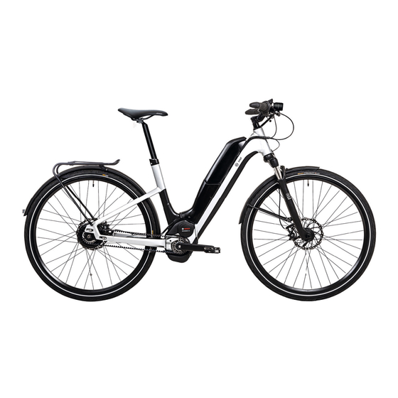
Ihr Fahrzeug 1.2. Fahrzeugübersicht ⑦ ① ⑤ ⑥ ② ③ ④ 1 NuVinci-Nabe 7 Display & Bedieneinheit 2 Gates Carbon Drive Riemen 3 Bosch Performance Cruise Motor 4 Bosch PowerPack 500 Akku 5 Typenschild (unter dem Akku) 6 Seriennummer (unter dem Unterrohr) Bitt e noti eren Sie die Seriennummer des UD1 hier:___________________________ 1.3. -
Page 10: Nutzung Eines Anhängers Oder Kindersitzes
Inbetriebnahme 1.4. Nutzung eines Anhängers oder Kindersitzes Aufgrund der Vielzahl verfügbarer Anhänger/Kindersitze kann HNF keine generelle Freigabe erteilen. Halten Sie Rücksprache mit HNF oder einem fachkundigen Händ- ler um die Kompatibilität des Anhängers/Kindersitzes zum Pedelec zu prüfen. Abhängig von der Bauart des Anhängers muss ggf. der Luftdruck am Hinterrad erhöht werden. -
Page 11: Lenkerhöhe Einstellen
Inbetriebnahme Die Satt elstützenklemmschraube ist fest genug angezogen, wenn sich die Satt elstütze nicht verdrehen lässt bzw. unter Belastung mitt els Ihres Körpergewichts nicht ins Sitzrohr abrutscht. Bruchgefahr des Sitzrohrs mit möglicher Folge eines Unfalls, wenn Sie die Satt elstütze zu weit ausziehen. ->... -
Page 12: Ein-/Ausschalten Des Antriebs
Inbetriebnahme • Akku einsetzen: Zum Einsetzen des Akkus setzen Sie ihn mit den Kontakten auf die untere Hal- terung und kippen ihn bis zum Anschlag in die obere Halterung, bis das Schloss hörbar einrastet. 2.4. Ein-/Ausschalten des Antriebs • Schieben Sie zunächst den beigelegten Intuvia-Bordcomputer auf die Halterung am Lenker. -
Page 13: Scheibenbremsen Einbremsen
Vor jeder Fahrt 2.7. Scheibenbremsen einbremsen Im Auslieferungszustand besitzt Ihr Bremssystem zunächst nur eine schwache Bremswirkung, da die Oberfl ächen von Bremsscheibe und Bremsbelägen noch nicht eingebremst sind. Bei Ihrem neuen Pedelec und auch wenn Sie Bremsscheibe und Bremsbeläge wechseln, sollten Sie die Scheibenbremsen wie folgt einbremsen: •... -
Page 14: Bremsanlage Überprüfen
Sie den Hebel mehrmals hintereinander an („Pumpen“). Prüfen Sie, ob sich der Druckpunkt verhärtet. In diesem Fall und wenn die Lage des Druckpunkts während der Fahrt wandert, muss die Bremsanlage durch den HNF-NICOLAI-Service oder in einer qualifizierten Fachwerkstatt entlüftet werden. •... -
Page 15: Federgabel Überprüfen
Prüfen Sie, ob lose Teile zu sehen und zu hören sind. Gehen Sie dem Ur- sprung der losen Teilen nach und prüfen Sie ob diese mit dem korrekten Anzugs- drehmoment befestigt sind. Wenden Sie sich gegebenenfalls an den HNF-NICOLAI- Service oder an einen qualifizierten Fachhändler. -
Page 16: Bedienung
Bedienung Bosch Antriebssystem Bedienung 4.1. Bosch-Antriebssystem OBJ_BUCH-2795-002.book Page 2 Wednesday, April 19, 2017 11:55 AM Die folgenden Seiten zeigen die Bedienungsanleitung der Robert Bosch GmbH für das Bosch eBike System MY18. 4.1.1. Intuvia Bordcomputer TURBO SPORT TOUR KM/H PMWH KM/H Reichweite... - Page 17 OBJ_BUCH-2795-002.book Page 3 Wednesday, April 19, 2017 11:55 AM Bedienung Bosch Antriebssystem Bosch eBike Systems 1 270 020 XBI | (19.4.17)
- Page 18 Bedienung Bosch Antriebssystem Deutsch–1 Sicherheitshinweise 7 USB-Buchse 8 Schutzkappe der USB-Buchse Lesen Sie alle Sicherheitshinweise und An- 9 Bedieneinheit weisungen. Versäumnisse bei der Einhaltung 10 Taste Anzeigenfunktion „i“ an der Bedieneinheit der Sicherheitshinweise und Anweisungen 11 Taste Unterstützung senken/nach unten blättern „–“ können elektrischen Schlag, Brand und/oder schwere Verletzungen verursachen.
- Page 19 Bedienung Bosch Antriebssystem Deutsch–2 Montage Der Antrieb wird aktiviert, sobald Sie in die Pedale treten (außer in der Funktion Schiebehilfe oder im Unterstützungs- Akku einsetzen und entnehmen level „OFF“). Die Motorleistung richtet sich nach dem einge- stellten Unterstützungslevel am Bordcomputer. Sobald das Zum Einsetzen des eBike-Akkus in das eBike und zum Entneh- System aktiviert wird, erscheint für kurze Zeit „Active men lesen und beachten Sie die Betriebsanleitung des Akkus.
- Page 20 Bedienung Bosch Antriebssystem Deutsch–3 Bordcomputer ein-/ausschalten Unterstützungslevel einstellen Zum Einschalten des Bordcomputers drücken Sie kurz die Sie können an der Bedieneinheit 9 einstellen, wie stark Sie Ein-Aus-Taste 5. Der Bordcomputer kann (bei ausreichend der eBike-Antrieb beim Treten unterstützt. Der Unterstüt- geladenem internem Akku) auch eingeschaltet werden, wenn zungslevel kann jederzeit, auch während der Fahrt, geändert er nicht in die Halterung eingesetzt ist.
- Page 21 Bedienung Bosch Antriebssystem Deutsch–4 Anzeigen und Einstellungen des Bordcomputers Durch die Wahl des richtigen Ganges können Sie bei gleichem Krafteinsatz die Geschwindigkeit und die Reichweite erhöhen. Geschwindigkeits- und Entfernungsanzeigen Folgen Sie deshalb den Schaltempfehlungen, die Ihnen durch In der Tachometeranzeige f wird immer die aktuelle die Anzeigen g und h auf Ihrem Display gegeben werden.
- Page 22 Bedienung Bosch Antriebssystem Deutsch–5 Um die Grundeinstellungen zu ändern, drücken Sie zum – „Betriebszeit gesamt“: Anzeige der gesamten Fahrdauer Verringern bzw. Blättern nach unten die Ein-Aus-Taste 5 mit dem eBike (nicht änderbar) neben der Anzeige „–“ oder zum Erhöhen bzw. Blättern nach –...
- Page 23 Bedienung Bosch Antriebssystem Deutsch–6 Code Ursache Abhilfe interner Zeitüberschreitungs-Fehler Starten Sie das System neu. Falls das Problem weiterhin besteht, kontaktieren Sie Ihren Bosch eBike-Händler. Es ist in diesem Fehlerzu- stand nicht möglich, sich im Grundeinstellungsmenü den Reifenumfang anzeigen zu lassen oder anzupassen. interner Akku des Bordcomputers leer Bordcomputer aufladen (in der Halterung oder über USB-Anschluss) Software-Versionsfehler Starten Sie das System neu.
- Page 24 Bedienung Bosch Antriebssystem Deutsch–7 Code Ursache Abhilfe 595, 596 Kommunikationsfehler Überprüfen Sie die Verkabelung zum Getriebe und starten Sie das System neu. Falls das Problem weiterhin besteht, kontaktieren Sie Ihren Bosch eBike-Händler. interner Akkufehler während des Trennen Sie das Ladegerät vom Akku. Starten Sie das eBike-System neu. Ladevorgangs Stecken Sie das Ladegerät an den Akku an.
- Page 25 Bedienung Bosch Antriebssystem Deutsch–8 Wartung und Service Entsorgung Antriebseinheit, Bordcomputer inkl. Bedieneinheit, Wartung und Reinigung Akku, Geschwindigkeitssensor, Zubehör und Verpa- ckungen sollen einer umweltgerechten Wiederver- Alle Komponenten inklusive der Antriebseinheit dürfen nicht wertung zugeführt werden. ins Wasser getaucht oder mit Druckwasser gereinigt werden. Werfen Sie eBikes und ihre Komponenten nicht in den Verwenden Sie für die Reinigung Ihres Bordcomputers ein Hausmüll!
-
Page 26: Drive Unit Cruise
Bedienung Bosch Antriebssystem 4.1.2. Drive Unit Cruise 0 275 007 PDC | (10.5.17) Bosch eBike Systems... - Page 27 Bedienung Bosch Antriebssystem Deutsch–1 Sicherheitshinweise Nehmen Sie keinerlei Veränderungen an Ihrem eBike- System vor oder bringen Sie keine weiteren Produkte Lesen Sie alle Sicherheitshinweise und An- an, welche geeignet wären, die Leistungsfähigkeit weisungen. Versäumnisse bei der Einhaltung Ihres eBike-Systems zu erhöhen. Sie verringern hiermit der Sicherheitshinweise und Anweisungen in der Regel die Lebensdauer des Systems und riskieren können elektrischen Schlag, Brand und/oder...
- Page 28 Bedienung Bosch Antriebssystem Deutsch–2 Montage Technische Daten Antriebseinheit Drive Unit Cruise Akku einsetzen und entnehmen Sachnummer 0 275 007 063 Zum Einsetzen des eBike-Akkus in das eBike und zum Entneh- Nenndauerleistung men lesen und beachten Sie die Betriebsanleitung des Akkus. Drehmoment am Antrieb Geschwindigkeitssensor überprüfen max.
- Page 29 Bedienung Bosch Antriebssystem Deutsch–3 Der Antrieb wird aktiviert, sobald Sie in die Pedale treten (außer – „SPORT“/„eMTB“ in der Funktion Schiebehilfe, siehe „Schiebehilfe ein-/ausschal- „SPORT“: kraftvolle Unterstützung, für sportives Fahren ten“, Seite Deutsch–3). Die Motorleistung richtet sich nach auf bergigen Strecken sowie für Stadtverkehr dem eingestellten Unterstützungslevel am Bordcomputer.
- Page 30 Bedienung Bosch Antriebssystem Deutsch–4 Fahrradbeleuchtung ein-/ausschalten Erste Erfahrungen sammeln Es ist empfehlenswert, die ersten Erfahrungen mit dem eBike In der Ausführung, bei der das Fahrlicht durch das eBike- abseits vielbefahrener Straßen zu sammeln. System gespeist wird, können über den Bordcomputer gleichzeitig Vorderlicht und Rücklicht ein- und ausgeschaltet Probieren Sie unterschiedliche Unterstützungslevel aus.
- Page 31 Bedienung Bosch Antriebssystem Deutsch–5 Wartung und Service Wartung und Reinigung Achten Sie beim Wechsel der Lampen darauf, ob die Lampen mit dem Bosch eBike-System kompatibel sind (fragen Sie Ihren Fahrradhändler) und die angegebene Spannung über- einstimmt. Es dürfen nur Lampen gleicher Spannung ge- tauscht werden.
-
Page 32: Akku
Bedienung Bosch Antriebssystem 4.1.3. Akku OBJ_BUCH-2032-006.book Page 4 Thursday, May 4, 2017 3:28 PM 0 275 007 XPX | (4.5.17) Bosch eBike Systems 7 °... - Page 33 Bedienung Bosch Antriebssystem Deutsch–1 Sicherheitshinweise Bei falscher Anwendung kann Flüssigkeit aus dem Akku austreten. Vermeiden Sie den Kontakt damit. Bei Lesen Sie alle Sicherheits- zufälligem Kontakt mit Wasser abspülen. Wenn die hinweise und Anweisungen. Flüssigkeit in die Augen kommt, nehmen Sie zusätzlich Versäumnisse bei der Einhal- ärztliche Hilfe in Anspruch.
- Page 34 Bedienung Bosch Antriebssystem Deutsch–2 Produkt- und Leistungsbeschreibung 4 Ein-Aus-Taste 5 Schlüssel des Akkuschlosses Abgebildete Komponenten 6 Akkuschloss 7 Obere Halterung des Standard-Akkus Die Nummerierung der abgebildeten Komponenten bezieht sich auf die Darstellungen auf den Grafikseiten. 8 Standard-Akku Alle Darstellungen von Fahrradteilen außer den Akkus und 9 Untere Halterung des Standard-Akkus ihren Halterungen sind schematisch und können bei Ihrem 10 Abdeckkappe (Lieferung nur bei eBikes mit 2 Akkus)
- Page 35 Bedienung Bosch Antriebssystem Deutsch–3 Hinweis: Der Akku wird teilgeladen ausgeliefert. Um die volle Ladevorgang bei zwei eingesetzten Akkus Leistung des Akkus zu gewährleisten, laden Sie ihn vor dem Sind an einem eBike zwei Akkus angebracht, so können beide ersten Einsatz vollständig mit dem Ladegerät auf. Akkus über den nicht verschlossenen Anschluss geladen wer- den.
- Page 36 Bedienung Bosch Antriebssystem Deutsch–4 Ziehen Sie den Schlüssel 5 nach dem Abschließen immer aus Überprüfen Sie vor dem Einschalten des Akkus bzw. des dem Schloss 6. Damit verhindern Sie, dass der Schlüssel eBike-Systems, dass das Schloss 6 abgeschlossen ist. herausfällt bzw. dass der Akku bei abgestelltem eBike durch Zum Einschalten des Akkus drücken Sie die Ein-Aus-Taste 4.
- Page 37 Bedienung Bosch Antriebssystem Deutsch–5 Lagerungsbedingungen Beim Transport durch gewerbliche Benutzer oder beim Trans- port durch Dritte (z.B. Lufttransport oder Spedition) sind be- Lagern Sie den Akku möglichst an einem trockenen, gut belüf- sondere Anforderungen an Verpackung und Kennzeichnung teten Platz. Schützen Sie ihn vor Feuchtigkeit und Wasser. Bei zu beachten (z.B.
-
Page 38: Ladegerät
OBJ_BUCH-2031-006.book Page 5 Wednesday, April 19, 2017 9:54 AM Bedienung Bosch Antriebssystem 4.1.4. Ladegerät OBJ_BUCH-2031-006.book Page 2 Wednesday, April 19, 2017 9:54 AM Bosch eBike Systems 0 275 007 XCX | (19.4.17) Standard Charger eBike Battery Charger 36-4/230 Standard Charger 0 275 007 907 Input: 230V 50Hz 1.5A... - Page 39 Bedienung Bosch Antriebssystem Deutsch–1 Sicherheitshinweise Beaufsichtigen Sie Kinder bei Benutzung, Reinigung und Wartung. Damit wird sichergestellt, dass Kinder nicht Lesen Sie alle Sicherheits- mit dem Ladegerät spielen. hinweise und Anweisungen. Kinder und Personen, die aufgrund ihrer physischen, Versäumnisse bei der Einhal- sensorischen oder geistigen Fähigkeiten oder ihrer tung der Sicherheitshinweise Unerfahrenheit oder Unkenntnis nicht in der Lage sind,...
- Page 40 Bedienung Bosch Antriebssystem Deutsch–2 Technische Daten Ladegerät Standard Charger Standard Charger Compact Charger (36–4/230) (36–4/100-230) (36–2/100-240) Sachnummer 0 275 007 907 0 275 007 923 0 275 007 915 Nennspannung 207...264 90...264 90...264 Frequenz 47...63 47...63 47...63 Akku-Ladespannung Ladestrom (max.) Ladezeit –...
- Page 41 Bedienung Bosch Antriebssystem Deutsch–3 Der Ladezustand wird mit der Akku-Ladezustandsanzeige 9 Ursache Abhilfe am Akku und mit den Balken auf dem Bordcomputer ange- Kein Ladevorgang möglich (keine Anzeige am Akku) zeigt. Stecker nicht richtig Alle Steckverbindungen Während des Ladevorgangs leuchten die LEDs der Ladezu- eingesteckt überprüfen.
-
Page 42: Nuvinci N380 Nabenschaltung
Bedienung 4.2. NuVinci N380 Nabenschaltung Über einen Drehgriff können Sie die Übersetzung stufenlos anpassen. Drehen Sie den Drehgriff vom Körper weg, um die Übersetzung zu ver- ringern, z. B. für das Anfahren oder für Bergauf- fahrten. Drehen Sie den Drehgriff zum Körper hin, um die Übersetzung zu erhöhen und mit schnelleren Geschwindigkeiten zu fahren. -
Page 43: Bremsanlage
Bedienung mit Zahnkranz aufziehen mit Hebel aufziehen 4.4. Bremsanlage Ihr UD1 ist mit hydraulischen Scheibenbremsen ausgestatt et, die Sie bei Bedarf schnell und sicher zum Stehen bringen. Benutzen Sie beide Bremsen gleichzeiti g für eine opti male und sichere Bremsung. Der linke Bremshebel wirkt auf die Vorderrad- bremse, der rechte Bremshebel auf die Hinterradbremse. -
Page 44: Rockshox Paragon Federgabel
Bedienung 4.5. RockShox Paragon Federgabel Über das so genannte Turnkey-System kann die Federgabel arreti ert werden. Turn- key befi ndet sich an der rechten Seite der Gabelkrone. Es gibt zwei Positi onen: • “Open”: In dieser Positi on ist die Dämpfung geöff net, die Gabel federt. -
Page 45: Ergonomieeinstellung
Ergonomieeinstellung Ergonomieeinstellung 5.1. Sattelposition und -neigung einstellen Die Sattelposition sollte per Knielot ermittelt werden. Das Knielot ist eine beispielsweise durch eine Schnur mit daranhängendem Gewicht ermittelbare senkrechte Linie von der Knievor- derseite durch die Pedalachse (bei waagerechter Kurbelposition). Setzen Sie sich in der oben aufgezeigten Position mit waagerechten Kurbelarmen auf das Pedelec und lassen Sie eine zweite Person das Knielot ermitteln. -
Page 46: Winkel Der Bremshebel
Position ① ① Instandhaltung Damit das Pedelec funktionsfähig und sicher bleibt, muss es regelmäßig gewartet werden. Beachten Sie bitte vor jeder Instandhaltungsmaßnahme die nachfolgen- den Informationen. HNF-NICOLAI bietet ein Servicekonzept an. Informieren Sie sich unter www.hnf-nicolai.com... -
Page 47: Liste Der Verschleißteile
Die Instandhaltung setzt technische Fähigkeiten voraus. Sie sind selbst verantwortlich für die korrekte Durchführung der Instandhaltung. -> Sollten Sie sich die Arbeiten nicht zutrauen, geben Sie das Rad bei einem Fachhändler zur Wartung, oder kontakti eren Sie den HNF-NICOLAI Service. Ist das Antriebssystem eingeschaltet, so besteht Verletzungsgefahr bei Wartungsar- beiten! Ihre Hände können bei anlaufendem... -
Page 48: Empfohlene Wartungsintervalle
Die Wartungsbedürft igkeit Ihres Pedelec hängt von dessen Nutzung ab und lässt sich deshalb nicht präzise angeben. Sie sollten das Pedelec mindestens einmal jährlich zur Inspekti on bei einem Fachhändler abgeben oder vom HNF-NICOLAI- Service warten lassen. Als Anhaltspunkt schlagen wir Ihnen die folgenden Wartungsintervalle vor: einmalig nach 100 - 300 km •... -
Page 49: Akku
Instandhaltung 6.4. Akku Während der Benutzung bestimmt vor allem die Leistungsabforderung die Lebensdauer des Akkus. Häufige Nutzung hoher Unterstützungsstufen senkt die Lebensdauer des Akkus. Während der Lagerung/Nichtnutzung sind folgende Faktoren relevant für die Lebensdauer: • Lagerungstemperatur. Optimal: 0-20 °C. Temperaturen über 30 °C bzw. das Abstellen des Bikes mit Akku in der prallen Sonne reduzieren die Lebensdauer des Akkus. -
Page 50: Hinterrad Ausbauen
Instandhaltung • Schieben Sie die Transportsicherung zwi- schen die Bremsbeläge. Hydraulische Scheibenbremsen dürfen bei ausgebautem Laufrad nicht betäti gt werden. Die Bremskolben fahren sonst möglicherweise vollstän- dig zusammen. -> Schieben Sie sofort nach dem Ausbau des Laufrads eine gelbe Trans- portsicherungen zwischen die Bremsbeläge. -
Page 51: Reifen/Schlauch Wechseln
Instandhaltung • Ziehen Sie das Hinterrad mit leichtem Rütteln nach unten aus dem Rahmen heraus. • Nehmen Sie den Riemen ohne Verdrehen von der Riemenscheibe hinten ab. • Stecken Sie eine gelbe Transportsicherung zwischen die Bremsbeläge, um ein versehentliches Verstellen des Bremsbelagabstands zu vermeiden. Wenn das Abheben der Zugstopper sich schwierig gestaltet, können Sie den Vorgang durch Vergrößerung des Schaltzug-Spiels vereinfachen. -
Page 52: Vorderrad Einbauen
Instandhaltung 6.6.4. Vorderrad einbauen • Nehmen Sie (wenn eingesteckt) die gelbe Transportsicherung zwischen den Bremsbelägen heraus. • Fädeln Sie das Vorderrad vorsichti g in die Gabel ein. Achten Sie darauf, dass die Bremsscheibe zwischen die Bremsbeläge gleitet. • Drehen Sie die Plasti kmutt er am Ende des Schnellspanners einige Umdrehun- gen zu. -
Page 53: Nuvinci-Nabenschaltung Einstellen
Bremsen Da es sich um ein hydraulisches Bremssystem handelt, sind Ihre Wartungsmöglich- keiten beschränkt. Arbeiten an der Hydraulik sollten Sie vom HNF-NICOLAI-Service oder einer Fachwerkstatt durchführen lassen. Kontaktieren Sie den Service in jedem Fall, wenn der Druckpunkt der Bremsen schwankt. -
Page 54: Bremsbeläge Überprüfen
Instandhaltung 6.8.2. Bremsbeläge überprüfen Die Bremsbeläge müssen ausgetauscht werden, wenn sie • nur noch 2,5 mm dick sind (Höhe von Trägerplatt e und Reibbelag) • mit Öl in Berührung kommen (führt zu geringer Bremsleistung) Zum Überprüfen der Bremsbelagstärke nutzen Sie die gelbe Transportsicherung: •... -
Page 55: Reinigung Und Pflege
Reinigung und Pfl ege Reinigung und Pfl ege • Wenn notwendig reinigen Sie das Pedelec mit Wasser und einem weichen Schwamm oder einer weichen Bürste. • Der Gates Carbon Drive-Riemen wird ebenfalls mit Wasser gereinigt und muss nicht geschmiert werden. • Die Kontakte der Batt erie und der Batt erieaufnahme am Rahmen können Sie mit einem feuchten Tuch abwischen. -
Page 56: Lenker Verdrehen
Transport am/auf dem Auto Li-Ion Akkus unterliegen den Anforderungen des Gefahrgutrechts. Private Nutzer können den Akku ohne Auflagen auf der Straße transportieren. Bei gewerblichen Transporten (z. B. Spedition) sind nationale Vorschriften zu Verpackung und Kennzeichnung zu beachten (z. B. ADR). 8.1. -
Page 57: Technische Daten
Technische Daten Technische Daten 9.1. Komponentenliste Rahmen HNF-NICOLAI Tiefeinsteiger, S/M oder L/XL Chassis Gabel RockShox Paragon silver, 65mm Motor Bosch Performance Line Cruise 25 Antriebs- Batterie Bosch Rahmenakku 500 Wh system Display Bosch Intuvia (optional: Nyon) Schaltung NuVinci N380 Nabe mit C3 Shifter (optional: C8 Shifter) -
Page 58: Gewichte
Technische Daten 9.2. Gewichte Batteriegewicht 2,5 kg Leergewicht inkl. Akku ca. 25,5 kg Zulässige Zuladung gesamt (Fahrer+Ausrüstung+Packtaschen) 125 kg 9.3. Anzugsdrehmoment der Schrauben Teil Moment/Nm Bosch-Remote an Lenker Bosch-Displaybefestigung Bremsbelag-Sicherungsschraube max. 2,5 Lenkergriffe Bremsscheiben (6x T25-Schraube) max. 4 Bremsgriffe (Klemmung am Lenker) max. -
Page 59: Sachmängelhaftung
Sachmängelhaftung Sachmängelhaftung Gesetzlich ist eine 24-monatige Sachmängelhaftung festgelegt, die mit dem Tag des Kaufs beginnt. Für die Inanspruchnahme der Sachmängelhaftung sind die Originalrechnung vorzu- legen und durchgeführte Inspektionen nachzuweisen. Sie haben Anspruch auf die Gewährleistung unter folgenden Voraussetzungen: • Es liegt ein Herstellungs-, Material- oder Informationsfehler vor. •... -
Page 60: Eg-Konformitätserklärung
HNF GmbH Bahnhofstrasse 150 16359 Biesenthal Wir, die HNF GmbH, erklären, dass die Maschine HNF-NICOLAI UD1 in der Ausführung als Pedelec allen einschlägigen Bestimmungen der Maschinenrichtlinie 2006/42/EG entspricht. Weiterhin entspricht die Maschine den folgenden Richtlinien: Richtlinie der elektromagnetischen Verträglichkeit 2014/30/EU •... -
Page 61: Entsorgung
Entsorgung Entsorgung Dieses Symbol auf Ihrem Pedelec weist darauf hin, dass das Produkt gemäß WEEE-Richtlinie (2012/19/EU; Richtlinie über Elektro- und Elektronik-Altgeräte), Batt erien-Richtlinie (2066/66/EG) und nati onalen Gesetzen zur Umsetzung dieser Richtlinien nicht über den Hausmüll entsorgt werden darf. Bitt e führen Sie das Pedelec am Ende seiner Lebensdauer einer örtlichen Sammel- stelle zu. - Page 62 Notizen...
- Page 63 UD1 Pedelec Manual (Translati on)
- Page 64 Content Your vehicle 1.1. Intended use 1.2. Vehicle overview 1.3. Scope of delivery 1.4. Use of a trailer or child seat Commissioning 2.1. Adjusting the saddle height 2.2. Adjusting handlebar height 2.3. Removing/installing the battery 2.4. Switching the drive on/off 2.5. Adjusting the assistance level 2.6. Switching the light on/off 2.7. Bedding-in brake pads Before every ride 3.1. Checking the tires 3.2. Checking the brake system 3.3. Checking the belt 3.4. Battery: Checking the attachment and charge level 3.5. Checking the suspension fork 3.6.
- Page 65 Maintenance 6.1. List of wear parts 6.2. Recommended maintenance intervals 6.3. After an accident 6.4. Battery 6.5. Tyres 6.6. Changing a tyre/tube 6.6.1. Removing the front wheel 6.6.2. Removing the rear wheel 6.6.3. Changing the tyre/tube 6.6.4. Fitting the front wheel 6.6.5. Fitting the rear wheel 6.7. Adjusting the NuVinci gear hub 6.8. Brakes 6.8.1. Brake pad and brake disc wear 6.8.2. Checking the brake pads 6.8.3. Checking the brake discs 6.9. Adjusting the headlight range Cleaning and care Transporting on a car 8.1. Turning the handlebar 8.2.
- Page 66 This indicates useful informati on regarding the handling of the product. Important informati on! The manual for your HNF-NICOLAI UD1 is regularly checked to ensure it is up to date. This manual refl ects the state of knowledge at the ti me of going to press. We therefore recommend that you visit our website www.hnf-nicolai.com to see if there have been any changes. The latest...
-
Page 67: Your Vehicle
Your vehicle Your vehicle We congratulate you on your purchase of the HNF-NICOLAI UD1 with BOSCH drive technology. You have chosen a means of transport that offers the latest technology, which will provide you with completely new mobility options. With our Pedelec1, we placed great emphasis on the technical quality of the individual components and are convinced that you will enjoy your UD1 for many years to come. The UD1 is a bike that assists the cyclist with an electric motor. This assistance is adjusted via a control, which evaluates the data from three sensors (speed, cadence and torque) and regulates the motor based on the selected level of assistance. If a speed of 25 km/h is reached, the electric motor switches off. However, you can ride faster than 25 km/h on your own without electric motor assistance. In Europe, the pedelec is excluded from Type approval2. It does not have to be approved or carry an insurance plate. The cyclist does not require a licence. For your own safety, we recommend that you always wear a suitable helmet and protection glasses. 1.1. Intended use Your HNF-NICOLAI UD1 is designed to carry one person on asphalt roads, paved and unpaved paths. The permitted load (cyclist + luggage + trailer) is 125 kg. The UD1 is suitable for use with a trailer (see section 1.4). The UD1 is not designed for the following: • Race/competition use • Cleaning with a strong jet of water • Transport on the outside of a car in the rain without covering the motor/display and removing the battery • Charging the vehicle outdoors in wet conditions The intended use is further limited by: • The safety instructions in this manual • The “Technical specifications” chapter in this manual •... - Page 68 • People with limited physical, sensory or mental capabiliti es • People who cannot operate the vehicle safely due to their height Modifi cati ons to your HNF-NICOLAI UD1 that increase motor performance or increase the maximum assistance speed, put your safety at risk and convert the vehicle from a pedelec to a moped. This may result in traffi c, licensing, insurance, as well as regulatory and criminal consequences! Rotati ng parts, such as wheels, pulleys, cranks or pedals, can pull in clothing, stowed items and even body parts. For example, your scarf or...
-
Page 69: Vehicle Overview
Your Vehicle 1.2. Vehicle overview ⑦ ① ⑤ ⑥ ② ③ ④ 1 NuVinci CVT hub 7 Intuvia on-board computer & control 2 Gates Carbon Drive belt 3 Bosch Performance Cruise drive unit 4 Bosch Powerpack 500 batt ery 5 Nameplate (below batt ery) 6 Serial number (below downtube) Please write the serial number of your UD1 here:____________________________ 1.3. Scope of delivery • Bosch charger • Bosch Intuvia on-board computer • Screw for securing the Intuvia on-board computer • 2 keys for batt ery lock • 2 transport locks for the Magura MT4 •... -
Page 70: Use Of A Trailer Or Child Seat
Comissioning 1.4. Use of a trailer or child seat Due to the large number of available trailer / child seats, HNF can not give general approval. Consult with HNF or a qualified dealer to check the compatibility of the trailer / child seat with the Pedelec. Depending on the type of trailer, the tire pressure of the rear wheel may need to be increased. Remove the loaded trailer from the connection point to the pedelec and hold it at the level of the connection point with your hand. If you feel weight on your hand, you should increase the tire pressure of the rear wheel. When using a child seat, increase the air pressure in the wheel above which the child seat is located. -
Page 71: Adjusting Handlebar Height
Comissioning Risk of breakage of upper seat tube if you pull the seatpost out too far. Consequence might be accident or injury! -> Pull the seatpost out only unti l the minimum inserti on depth mark is just visible. 2.2. Adjusti ng handlebar height Handlebar height is adjusted by changing the angle of the stem. The adjustment is done in two steps (blue semicircles show procedure of lift ing the handlebar). 1. Change Stem angle • Loosen both red marked srews unti l stem angle may be changed. • Rotate stem unti l desired handlebar height is reached. • Reti ghten both screws with 14-15 Nm. 2. Turn handlebar • Loosen all 4 screws on the front clamping plate of the stem unti l the handlebar is turnable. -
Page 72: Switching The Drive On/Off
Comissioning Installation: • Place the bottom of the battery with the contacts in the lower bracket of the battery holder . • Press the battery on its upper end downwards until it clicks into place. 2.4. Switching the drive on/off • First, slide the supplied Intuvia on-board computer onto the bracket on the handlebar. • To turn the system on/off, press the on but- ton located on Intuvia or on battery. 2.5. Adjusting the assistance level To increase the assistance level, press the “+” button on the operating unit until the desired assistance level appears in Intuvia. To reduce the assistance level, press the “-” button. 2.6. Switching the light on/off Pressing the light button on Intuvia will turn the LED headlight and rear light on or off. Please refer to 4.1.1 Intuvia on-board computer for more detailed infor- mation. -
Page 73: Bedding-In Brake Pads
Before every ride 2.7. Bedding-in brake pads When delivered, your brake system initi ally only has a weak braking eff ect, as the surfaces of the brake disc and brake pads have not yet been used for braking. With your new vehicle and also if you change the brake disc and brake pads, you should bed-in the disc brakes as follows: • Accelerate the vehicle to approx. 25 km/h • Decelerate to a stop using both brakes • Repeat the procedure unti l the braking eff ect improves suffi ciently. Recom- mendati on for the Magura: 30x. Risk of roll-over when using the front wheel brake forcefully! You can go over the handlebar! -> Apply less force to the left brake lever or release the brake lever when you noti ce the rear wheel rising. Before every ride 3.1. -
Page 74: Checking The Brake System
• For hydraulic disc brakes, the pressure point on the brake lever must be stable. If the pressure point is not reached after two-thirds of the lever stroke, pull the lever several times in succession (“pumping”). Check if the pressure point stiffens. In this case and if the location of the pressure point moves while riding, the brake system must be bled by HNF-NICOLAI Service or by a qualified specialist workshop. • The brake discs must be free of oil. If you find oil on the brake discs, remove it with an alcohol-soaked cloth. The pressure point is defined as the position of the lever stroke at which the brake responds. If the brake works perfectly – i.e. there are no air bubbles in the hydraulic line – the pressure point will be the same lever... -
Page 75: Checking The Suspension Fork
Before every ride 3.5. Checking the suspension fork Check the suspension fork before every ride for: • cracks* • deformations* • oil leaks* • Deep scratches on the upper tubes (stanchion tubes) of the fork* • Dirt and contamination on the upper tubes (stanchion tubes) of the fork -> If the stanchion tubes of the fork are dirty, wipe them clean with a rag. *If any of these issues occur, contact HNF-NICOLAI Service or a specialist retailer for diagnosis and if necessary, repair. 3.6. Checking the screw fittings Before each ride, check that the quick-release axle on the frontwheel and the axle nuts on the rearwheel are ti ghtened firmly. Also, check that the following parts do not twist: • saddle • seatpost • handlebar • stem Lift the vehicle slightly and let it fall to the ground on the tyres. A rattle can have its origin in loose parts. Check the cause and, if necessary, tighten the parts again with the required tightening torque (see section 9.3). -
Page 76: Use
Bosch operating instructions 4.1. Bosch eBike system OBJ_BUCH-2795-002.book Page 2 Wednesday, April 19, 2017 11:55 AM The following pages show the operating instructions of Robert Bosch GmbH for the Bosch eBike system MY18. 4.1.1. Intuvia on-board computer TURBO SPORT TOUR KM/H PMWH KM/H Reichweite... - Page 77 OBJ_BUCH-2795-002.book Page 3 Wednesday, April 19, 2017 11:55 AM Bosch operating instructions Bosch eBike Systems 1 270 020 XBI | (19.4.17)
- Page 78 Bedienung operating instructions English–1 Safety Notes 7 USB port 8 Protective cap of USB port Read all safety warnings and all instruc- 9 Operating unit tions. Failure to follow the warnings and in- 10 Display-function button “i” on the operating unit structions may result in electric shock, fire 11 Decrease assistance level/scroll down button “–”...
- Page 79 Bosch operating instructions English–2 Assembly The drive is activated as soon as you step on the pedals (ex- cept for in the push assistance function or in assistance level “OFF”). The motor output depends on the settings of the as- Inserting and removing the battery pack sistance level on the on-board computer.
- Page 80 Bosch operating instructions English–3 Switching on/shutting down the on-board computer Setting the Assistance Level To switch on the on-board computer, briefly press the On/Off On the operating unit 9 you can set how much the eBike drive button 5. The on-board computer can also be switched on assists you while pedalling.
- Page 81 Bosch operating instructions English–4 For this reason, follow the shift recommendations provided – “Trip time”: Trip time since the last reset by indications g and h on your display. If indication g is dis- – “Range”: Estimated range of the available battery-pack played, you should shift to a higher gear with lower cadence.
- Page 82 Bosch operating instructions English–5 – “– English +”: You can change the language of the text in- – “ Service MM/YYYY”: This menu item is displayed dications. You can choose between German, English, when the bike manufacturer has set a fixed service ap- French, Spanish, Italian, Portuguese, Swedish, Dutch and pointment.
- Page 83 Bosch operating instructions English–6 Code Cause Corrective Measure Internal software error Restart the system. If the problem persists, contact your Bosch eBike dealer. Error at USB connection Remove the cable from the USB connection of the on-board computer. If the problem persists, contact your Bosch eBike dealer. Internal error of the on-board Have the on-board computer checked.
- Page 84 Bosch operating instructions English–7 Code Cause Corrective Measure Battery pack temperature error The eBike is outside of the permissible temperature range. Switch off the eBike system and allow the drive unit to either cool down or heat up to the permissible temperature. Restart the system. If the problem persists, contact your Bosch eBike dealer.
- Page 85 Bosch operating instructions English–8 Transport If you transport your eBike attached to the outside of your car, e.g. on a bike rack, remove the on-board com- puter and the eBike battery to avoid damaging them. (If the on-board computer cannot be fitted onto a bracket, it is not possible to remove it from the bicycle.
-
Page 86: Drive Unit Cruise
Bosch operating instructions 4.1.2. Drive Unit Cruise 0 275 007 PDC | (10.5.17) Bosch eBike Systems... - Page 87 Bosch operating instructions English–1 Safety Notes Do not make any modifications to your eBike system or fit any other products which would be suitable for in- Read all safety warnings and all instruc- creasing the performance of your eBike system. This tions.
- Page 88 Bosch operating instructions English–2 Assembly Technical Data Drive Unit Drive Unit Cruise Inserting and removing the battery pack Article number 0 275 007 063 For inserting and removing the eBike battery pack in/from the Rated continuous output eBike, please read and observe the battery pack operating in- Torque at drive, max.
- Page 89 Bosch operating instructions English–3 As soon as you stop pedaling when in normal operation, or as The motor output requested appears on the display of the on- soon as you have reached a speed of 25 km/h, the assistance board computer (not on Purion). The maximum motor output from the eBike drive is switched off.
- Page 90 Bosch operating instructions English–4 The eBike drive automatically switches off at speeds in excess Careful Handling of the eBike of 25 km/h. When the speed falls below 25 km/h, the drive is Please observe the operating and storage temperatures of the automatically available again. eBike components.
-
Page 91: Powerpack 500 Battery
Bosch operating instructions 4.1.3. PowerPack 500 battery OBJ_BUCH-2032-006.book Page 4 Thursday, May 4, 2017 3:28 PM 0 275 007 XPX | (4.5.17) Bosch eBike Systems 7 °... - Page 92 Bosch operating instructions English–1 Safety Notes Under abusive conditions, liquid may be ejected from the battery pack. Avoid contact. If contact accidentally Read all safety warnings and occurs, flush with water. If liquid contacts eyes, addi- all instructions. Failure to tionally seek medical help. Liquid ejected from the follow the warnings and in- battery pack may cause skin irritations or burns.
- Page 93 Bosch operating instructions English–2 Product Description and 4 On/Off button 5 Key of the battery pack lock Specifications 6 Battery-pack lock 7 Upper holder of the standard battery pack Product Features 8 Standard battery pack The numbering of the product features refers to the illustra- 9 Bottom holder of the standard battery pack tions on the graphics pages.
- Page 94 Bosch operating instructions English–3 Charging the Battery Pack If you have an eBike that is designed for two battery packs and you want to use it with only battery pack, cover off the con- Use only the Bosch charger provided with your eBike or tacts of the unused socket using the cover lid 10 provided be- an identical original Bosch charger.
- Page 95 Bosch operating instructions English–4 After locking, always remove the key 5 from the lock 6. This To switch on the battery pack, press the On/Off button 4. The prevents the key from falling out and the battery pack from LEDs of indicator 3 light up and at the same time indicate the being removed from unauthorised persons when the eBike is charge condition.
- Page 96 Bosch operating instructions English–5 Storage Conditions When being transported by commercial users or third parties (e.g. air transport or forwarding agency), special require- Store the battery pack in a dry, well-ventilated location. ments on packaging and labelling must be observed (e.g. ADR Protect the battery pack against moisture and water.
-
Page 97: Charger
OBJ_BUCH-2031-006.book Page 5 Wednesday, April 19, 2017 9:54 AM Bosch operating instructions 4.1.4. Charger OBJ_BUCH-2031-006.book Page 2 Wednesday, April 19, 2017 9:54 AM Bosch eBike Systems 0 275 007 XCX | (19.4.17) Standard Charger eBike Battery Charger 36-4/230 Standard Charger 0 275 007 907 Input: 230V 50Hz 1.5A Li-Ion... - Page 98 Bosch operating instructions English–1 Safety Notes Supervise children during use, cleaning and mainte- nance. This will ensure that children do not play with the Read all safety warnings and charger. all instructions. Failure to fol- Children or persons that owing to their physical, senso- low the warnings and instruc- ry or mental limitations or to their lack of experience or tions may result in electric...
- Page 99 Bosch operating instructions English–2 Technical Data Battery Charger Standard Charger Standard Charger Compact Charger (36–4/230) (36–4/100-230) (36–2/100-240) Article number 0 275 007 907 0 275 007 923 0 275 007 915 Rated voltage 207...264 90...264 90...264 Frequency 47...63 47...63 47...63 Output voltage Charging current (max.) Charging time –...
- Page 100 Bosch operating instructions English–3 The charging state is displayed by the battery charge-control Cause Corrective Measure indicator 9 on the battery and by the bars on the on-board No charging procedure possible (no indication on battery computer. pack) During the charging procedure, the LEDs of charge-control Plug not inserted correctly Check all plug connections.
-
Page 101: Nuvinci N380 Gear Hub
4.2. NuVinci N380 gear hub With the NuVinci gear hub transmission system, you can adjust the transmission rati o infi nitely via a twist grip. Turn the twist grip away from the body to reduce the transmission rati o, e.g. for starti ng up or for uphill riding. Turn the twist grip towards the body to increase the transmission rati o and ride at faster speeds. When at a standsti ll, only 50 to 70% of the transmission range is available on NuVinci hubs. The remaining range is only available while riding. -
Page 102: Brake System
Fitti ng with the sprocket Fitti ng with a lever 4.4. Brake system Your UD1 is equipped with hydraulic disc brakes that will stop you quickly and safely when needed. Use both brakes simultaneously for safe braking. The left brake lever acts on the front brake, the right brake lever on the rear brake. The brake system has fully automati c pad compensati on. This compensates for the wear of the brake pads and ensures that the pressure point of the brake always remains the same. The front brake has a stronger decelerati on eff ect than the rear brake. Therefore, practi ce targeted use of the front brake to familiarise yourself with the force of the brakes. Risk of roll-over when using the front wheel brake forcefully! You can go over the handlebar! -> Apply less force to the left brake lever or release the brake lever when... -
Page 103: Rockshox Paragon Suspension Fork
4.5. RockShox Paragon suspension fork The fork may be locked via the so-called Turnkey system. Turnkey can be found on the right side of the fork crown. Adjustment is possible between two points: • “Open”: In this positi on the forks damping circuit is open and the fork will react to shocks. • “Lock”: At light shocks, the fork is prevented from diving into travel. If you ride over a larger object in „lock“-positi on, the damping circuit will open briefl y and allow the the fork to absorb the shock. Aft erwards dam- ping circuit will be locked again. 4.6. Side stand Please note the following points when handling your side stand: Riding with the side stand folded out may result in a fall. Pushing the vehicle backwards with the side stand folded out can cause the stand to jam on the crank. -> Fold the stand in before starti ng to ride. The stand may break if you sit on the vehicle when the stand is folded out. -> Do not sit on the vehicle with the side stand folded out. 4.7. Tubus carrier The Tubus carrier is placed on the rear Wingee mudguard and may carry a load of 16 kg in total. -
Page 104: Ergonomic Setting
Ergonomic setting Ergonomic setting 5.1. Adjusting the saddle position and tilt The optimal horizontal position of the saddle can be determined by the knee plumb line. The knee plumb line is the vertical line from the front of the knee down and should ideally pass through the pedal axle or just in front of it. You can determine the knee plumb line by means of a string with a weight and a helper. Sit on the vehicle in the position shown above with horizontal crank arms and let a second person determine the knee plumb line. To adjust the saddle position and tilt, loosen the two Allen screws of the saddle clamp, which are located behind the seatpost under the saddle. You can now move the saddle horizontally and adjust the tilt. Set the tilt of the saddle horizontally or with the saddle tip inclined downwards slightly. Then tighten the screws to 9-10 Nm. 5.2. Brake lever You can adjust the brake lever position on the handlebar, the angle of the brake levers and the lever width. 5.2.1. Adjusting the brake lever position To hold the handlebar securely while braking, it is best to only grip the brake levers with your index and middle fingers. To achieve this position, you may need to move the lever sideways so that both fingers can grip the brake lever as shown in the photo. By loosening the two T25 screws on the handlebar clamp, the brake lever on the handlebar can be moved. You may also first have to loosen and move the Bosch control unit with a suitable Allen key. -
Page 105: Brake Lever Angle
rst phalanx of the 2 fi ngers in questi on. The lever width can be adjusted with a Torx 25 key. Adjust the screw at the marked positi on ① ① Maintenance In order to keep the vehicle functi onal and safe, it must be regularly maintained. Please note the following informati on before every maintenance measure. HNF-NICOLAI off ers a service concept. Find out more at www.hnf-nicolai.com Maintenance requires technical skills. You are responsible for the maintenance work being carried out correctly. -> If you do not feel confi dent doing the work, contact HNF-NICOLAI Ser- vice or have a bicycle workshop carry out maintenance on the bike. There is a risk of clamping and crushing during maintenance work. Your fi ngers could get stuck between moving parts. -> Pay careful att enti on to your hands and work. -
Page 106: List Of Wear Parts
• All moving parts (e.g. bearings) • Gear cables, cable housing • Hydraulic oil and lubricants • Handlebar grips • Paint and all surfaces Precise explanati ons regarding the wear of some parts can be found in the following secti ons. For most parts, the wear is due to fricti on. 6.2. Recommended maintenance intervals The maintenance needs of your vehicle depend on its use and therefore this cannot be indicated in general terms. You should have the vehicle serviced at least once a year by the HNF-NICOLAI service or a bicycle workshop. As a guide, we suggest the following maintenance intervals: once aft er 100-300 km • Check the ti ghtening torques of the grips, brake levers, saddle, seatpost, stem and handlebar • Check the spoke tension, if necessary true the wheel • Adjust the NuVinci shift cable clearance, if necessary... -
Page 107: After An Accident
6.3. Aft er an accident If parts of the drive system (cable, motor, batt ery) are visibly damaged due to an accident, there is a risk of electric shock. -> In this case, remove the batt ery immediately. Have the drive system checked by the HNF-NICOLAI service or a bicycle workshop trained in Bosch eBike system. Parts of your vehicle may be damaged due to an accident, which can cause a risk of breakage. -> In case of an accident, contact HNF-NICOLAI Service or a bicycle work- shop to have damaged parts such as the frame, fork, handlebar, stem, seatpost, pedal cranks and pedals checked and replaced if necessary. -
Page 108: Tyres
Maintenance 6.5. Tyres The tyres are subject to inevitable wear due to fricti on. You can reduce the tyre wear by ensuring the air pressure is high enough (secti on 3.1) and refraining from locking the tyres when braking. You will need to replace your tyres if the rubber tread is so worn down that the braid underneath becomes visible, or if the tyres have become porous due to ageing and frequent exposure to the sun. The following secti ons explain how to change the tyres. 6.6. Changing a tyre/tube 6.6.1. Removing the front wheel The wheels are easier to remove if you put the vehicle into a service stand or place it upside down on the saddle and handlebar. In the second procedure, please protect the display and bell from damage. • Fold the quick-release lever on the front wheel axle down by 180°. • Loosen the nut on quick-release axle some turns. The front wheel may now slide out of the dropouts of the fork. Hydraulic disc brakes must not be actuated when the wheel is removed. Otherwise, the brake pistons will run together completely. -> Immediately aft er removing the wheel, push a yellow transport lock between the brake pads. (see picture next page) 6.6.2. -
Page 109: Changing The Tyre/Tube
Maintenance If it is difficult to lift the pull-stop device, you can facilitate this process by increasing the shift cable clearance. See section 6.7. "Adjusting the NuVinci gear hub". • Lever the control cable end provided with the silver bolt off the hub interface, e.g. with a small screwdriver. • Loosen the axle nuts and external tab wash- ers on both sides of the hub. • Pull the rear wheel out of the frame by giving it a gentle shake. • Remove the belt from the rear pulley without twisting. • Insert a yellow transport lock between the brake pads to prevent accidental adjustment of the brake pad spacing. 6.6.3. Changing the tyre/tube • Unscrew the valve cap and large knurled nut from the valve. • Completely release the air by applying pressure to the valve pin in the centre of the valve. -
Page 110: Fitting The Front Wheel
Maintenance • Then lever the other side of the tyre onto the rim using tyre levers. • Turn the knurled nut onto the valve unti l it reaches the rim. • Infl ate the tyre to the maximum pressure indicated on the tyre wall so that the tyre sits evenly on the rim. It is normal to hear a “plop” when doing so. • Then lower the pressure to the desired value (see secti on 3.1.). • Screw the valve cap onto the valve. 6.6.4. Fitti ng the front wheel • Remove (when inserted) the yellow transport lock from between the brake pads. • Carefully thread the front wheel into the fork. Make sure that the brake disc slides between the brake pads. • Turn the quick-release axle nut a few turns while holding the quick release lever. • Fold the quick-release lever up, so that it is aligned parallel to the fork leg. The closing force should increase during closing. If not, reopen the quick-release lever and conti nue to fasten the nut. If the pretensioning of the quick-release is too low, the wheel can become loose while riding. There is a risk of accident! -> Always ti ghten the quick-release unti l the tensioning lever leaves a force-induced imprint on the palm of your hand when folding it down. -
Page 111: Adjusting The Nuvinci Gear Hub
If you increased the shift cable clearance to make it easier to remove the rear wheel, you will need to readjust it now. 6.7. Adjusting the NuVinci gear hub The gear shift quality of the NuVinci gear hub may decrease while the vehicle is in use. You can correct this by adjusting the shift cable clearance. • You can feel the shift cable clearance by gen- tly pulling on the end caps of the gear cables that run into the twist grip. • A clearance of 0.5 mm per pull is ideal. More than 2 mm clearance can adversely affect the gear shift quality of the system and the ser- vice life of the shift cable. 0,5 mm • To adjust turn both setscrews and check the amended clearance. 6.8. Brakes As it is a hydraulic braking system, your maintenance options are limited. Work on the hydraulics should be carried out by HNF-NICOLAI Service or a bicycle workshop. In any case, please contact HNF-NICOLAI Service or a bicycle workshop if the pres- sure point of the brakes fluctuates. 6.8.1. Brake pad and brake disc wear Brake pads and brake discs are subject to functional wear caused by friction between the two parts. The wear depends on the riding style, terrain, weather and ground conditions, meaning that no binding information can be given regarding the brake pads. Brake discs need to be replaced after approx. 4 to 5 changes of brake pad pairs, as they are made of a harder material. It is recommended to check the brake pads every 500 km. -
Page 112: Checking The Brake Pads
Maintenance 6.8.2. Checking the brake pads The brake pads must be replaced when they • are only 2.5 mm thick (height of carrier plate and fricti on lining) • come into contact with oil (leads to low braking power) To check the brake pad thickness, use the yellow transport lock supplied: • Pull the brake lever and insert the rear side of the transport lock between the carrier plates of the corresponding brake calliper. If the transport lock sti ll fi ts between the pads, they are not worn out. • Alternati vely, you can put the removed pads into the small notch in the transport lock. The pads are worn out when they fi t into the notch. 6.8.3. Checking the brake discs The brake discs must be replaced if they have a thickness of less than 1.8 mm. The thickness can be determined using a calliper, for example. 6.9. -
Page 113: Cleaning And Care
Cleaning and care Cleaning and care • If necessary, clean the vehicle with water and a soft sponge or soft brush. • The Gates Carbon Drive Belt is also cleaned with water and does not need to be lubricated. • The contacts of the batt ery and the batt ery holder on the frame can be wiped with a damp cloth. Wait unti l the contacts are dry before reatt aching the batt ery. A high-speed jet of water can cause damage to the bearings, NuVinci hub, Bosch batt ery, motor and display. -> Only use a weak garden hose that provides a slow jet of water. Oil or spray wax that gets onto the brake discs or pads dramati cally reduc- es brake performance. -> Prevent spray wax or oil from coming into contact with the brake discs or pads! Transporti ng on a car To avoid damage caused by transporti ng the vehicle on the outside of a car, observe the following instructi ons: The batt ery can become loose when the vehicle is being transported on... -
Page 114: Turning The Handlebar
Transporting on a car 8.1. Turning the handlebar It may be necessary to turn the handlebar during transport. In order to do so, pro- ceed as follows: • Loosen both red marked screws on the stem with a suitable Allen key. • Turn the stem into the desired position. • If you wish to transport the bike without a cyclist, it is sufficient to firmly both screws. • If you wish to restore the UD1 to its riding position, tighten the side crews with 14-15 Nm. 8.2. Installing/removing the pedals The right pedal has a right-hand thread and the left pedal has a left-hand thread on the pedal axle. The right pedal is screwed clockwise and the left pedal is screwed anticlockwise. • For installation, proceed as follows: • Grease the thread of the pedal axle and the crank sparingly. First screw the pedal in loosely by hand. Make sure that you place the parts at the correct angle to each other and do not tilt them. • Put the crank in a horizontal position so that the right pedal points towards the front wheel. -
Page 115: Technical Specifications
Technical specifications Technical specifications 9.1. Component list Frame HNF-NICOLAI low step-through, S/M oder L/XL Chassis Fork RockShox Paragon silver, 65mm Drive unit Bosch Performance Line Cruise 25 Bosch eBike Battery Bosch PowerPack 500 Wh system On-board computer Bosch Intuvia (optional: Nyon) Shifting system NuVinci N380 Hub with C3 Shifter (optional: C8 Shifter) Crank ISIS Miranda Delta 170 mm Front Sprocket Gates CDX for Bosch 24T Riding Belt Gates Carbon Drive Belt 111T braking Rear Sprocket Gates CDX for NuVinci 24T FW brakes Magura MT4, 180 mm RW brakes Magura MT4, 180 mm RW hub NuVinci N380 SE Rims Ryde Taurus, 622-21 Wheels... -
Page 116: Weights
Technical specifications 9.2. Weights Battery weight 2,5 kg Curb weight incl. battery approx. 25,5 kg Total permissible load (cyclist+equipment+panniers) 125 kg 9.3. Tightening torque of the screws Part Torque/Nm Bosch Purion on-board computer on handlebar Bosch-Displaybefestigung Brake pad locking screw max. 2,5 Handlebar grips Brake discs (6x T25 screw) max. 4 Brake levers (clamp on the handlebar) max. 4 Stem on handlebar 5 - 6 Stem on steerer tube / angle adjustment 14 - 15 Seatpost clamp 5 - 12 Seatpost saddle clamp 9 - 10 Sliding dropout side screws Brake adapter to fork/frame max. 6 Brake caliper to adapter/frame max. 6 Front sprocket lockring 20 - 25 Pedals 30 - 35... -
Page 117: Liability For Defects
Liability for defects Liability for defects In most European countries a 24-month warranty is stipulated by law, beginning on the day of purchase. For the defect liability claim, the original invoice must be submitted and ideally, any inspections performed must be verified. You are entitled to the warranty under the following conditions: • There is a manufacturing defect, material defect or information error. • The damage referred to in the complaint was already present at the time of delivery. • The product was not altered due to function-related wear or ageing. • The damage was not caused by violation of the intended use. • Battery: it has a residual capacity of less than 60% of the nominal capacity after a maximum of 500 charging cycles. One charging cycle is the complete charging of the battery with a single load or multiple partial charges (e.g. two half charges). -
Page 118: Ec Declaration Of Conformity
EC declaration of conformity HNF GmbH Bahnhofstrasse 150 16359 Biesenthal We, HNF GmbH, declare that the machine HNF-NICOLAI UD1 a Pedelec, meets all relevant provisions of Machinery Directive 2006/42/EC. Furthermore, the machine complies with the following directives: Directive of Electromagnetic compatibility 2014/30/EC •... -
Page 119: Disposal
Disposal Disposal This symbol on your vehicle indicates that, in accordance with the WEEE Directi ve (2012/19/EU; Waste Electrical and Elec- tronic Equipment Directi ve), the Batt eries Directi ve (2006/66/ EC) and nati onal laws implementi ng these Directi ves, the prod- uct may not be disposed of with household waste. Please take the vehicle to a local collecti on point at the end of its service life. Packaging materials must be separated by type and disposed of according to local regulati ons. You may return the batt ery to an e-bike retailer or send it to HNF for disposal in the supplied hazardous goods box: HNF GmbH -Entsorgung- Bahnhofstraße 150 16359 Biesenthal...
Need help?
Do you have a question about the UD1 PedelecW and is the answer not in the manual?
Questions and answers