Sign In
Upload
Manuals
Brands
SKF Manuals
Water Pump
143 Series
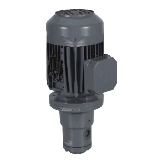
SKF 143 Series Gerotor Pump Units Manuals
Manuals and User Guides for SKF 143 Series Gerotor Pump Units. We have
2
SKF 143 Series Gerotor Pump Units manuals available for free PDF download: Assembly & Instruction Manual, Operating Instructions Manual
SKF 143 Series Assembly & Instruction Manual (80 pages)
gerotor pumps and pump units for SKF CircOil centralized lubrication systems
Brand:
SKF
| Category:
Water Pump
| Size: 2 MB
Table of Contents
Information Concerning EC Declaration of Conformity and EC Declaration of Incorporation
2
Table of Contents
4
Explanation of Symbols and Signs
6
Safety Instructions
8
General Safety Instructions
8
General Behavior When Handling the Product
8
Qualiied Technical Personnel
9
Electric Shock Hazard
10
System Pressure or Hydraulic Pressure Hazard
10
Operation
10
Assembly/Maintenance/Malfunction/Decommissioning/Disposal
11
Intended Use
12
Foreseeable Misuse
12
Disclaimer of Liability
13
Referenced Documents
13
Warning Labels on the Product
14
Residual Risks
15
Lubricants
17
General Information
17
Selection of Lubricants
17
Approved Lubricants
18
Lubricants and the Environment
19
Lubricant Hazards
19
Overview
20
Product Codes
21
Order Example
23
Assembly
24
General Information
24
Setup and Attachment
25
Installation Instructions
26
Information on Assembly Holes
27
Minimum Mounting Dimensions
27
Gerotor Pump
28
Gerotor Pump Design, Assembly
28
Mounting Dimensions
28
Assembly Holes and Minimum Mounting Dimensions
29
Technical Data
30
Installation of the Gerotor Pump
32
Installation of the Gerotor Pump with Pump Lange and Shaft Coupling
33
Gerotor Pump Unit
34
Foot Design, Type IM B34, Assembly Holes and Minimum Mounting Dimensions
34
Flange Design, Type IM B14, Assembly Holes and Minimum Mounting Dimensions
35
Technical Data
36
Assembly of Gerotor Pump Unit in Foot Design, Type IM B34
38
Electrical Motor Connection
40
Lubrication Line Arrangement
41
Note on the Rating Plate
43
Operating Instructions
45
Safety Instructions
46
General Information
46
Lubricants
46
Delivery, Returns, and Storage
47
Checking the Delivery
47
Returns
47
Lubrication Units
47
General Notes
47
Assembly
48
Information on Assembly
48
Functional Description
48
General System Description
48
Gerotor (Annular Gear) Pumps
49
Gerotor (Annular Gear) Pump Units
50
Operation/Decommissioning and Disposal
51
Operation
51
General
51
Commissioning
51
Recommissioning after Downtime
52
Temporary Shutdown
52
Decommissioning and Disposal
53
Maintenance
54
General Information
54
Maintenance Schedule
55
Malfunctions, Causes, and Remedies
56
Gerotor Pumps and Gerotor Pump Units
57
Technical Data
59
Characteristic Curves
59
Operating Viscosity, 20 MM 2 /S
60
Operating Viscosity, 140 MM 2 /S
61
Operating Viscosity, 750 MM 2 /S
61
Operating Viscosity, 1000 MM 2 /S
61
Viscosity-Temperature Relationship of Oils with Different Rated Viscosity
62
Viscosity Range
63
To 2000 MM 2 /S
64
Spare Parts
65
Appendix
67
IEC Squirrel Cage Motors
67
Principles
67
Voltage Code, Motor Design 50 /60 Hz
72
Installation Drawing and Dimensions
75
Technical Data
77
Advertisement
SKF 143 Series Operating Instructions Manual (48 pages)
ATEX-compliant gerotor pump units for SKF CircOil centralized lubrication systems
Brand:
SKF
| Category:
Water Pump
| Size: 2 MB
Table of Contents
Table of Contents
4
1 Safety Instructions
7
Special Safety Instructions Regarding
7
Explosion Protection
7
Operation in Potentially Explosive Atmospheres
8
Explosion Protection Marking
8
Explosion Protection Measures
8
Nullification of ATEX Approval
8
Prohibition of Certain Activities
8
Intended Use
9
Foreseeable Misuse
9
Modifications to the Product
9
Persons Authorized to Use the Product
9
General Safety Instructions
9
General Behavior When Handling the Product
10
Inspections Prior to Delivery
10
Emergency Pump Shut-Down
10
Referenced Documents
10
Transport, Assembly, Servicing, Repair, Maintenance
10
Initial Commissioning, Daily Startup
11
Cleaning
11
Identification of Hazards
11
Provision of Necessary Information
11
Duty to Provide Instruction and Training
11
Information on CE Marking
12
Instruction of Outside Fitters
12
Verification of Proper Usage
12
Provision of Personal Protective Gear
12
Existing Residual Risks
13
Warning Labels on the Product
15
2 Lubricants
16
General Information
16
Selection of Lubricants
16
Material Compatibility
16
Aging of Lubricants
16
Lubricants in Potentially Explosive Atmospheres
16
3 Overview, Functional Description
17
Assemblies
17
Product Codes
17
Order Example 143-21FD03E-RE+1GD
18
Functional Description of Gerotor Pump Units
18
Operation of the Gerotor Pump Units
19
4 Technical Data
20
Basic Data
20
Oil Lubrication Pump Units in Types IM B34 and IM B14
21
Delivery Rates and Characteristic Curves
21
Operating Viscosity, Characteristics 20 MM 2 /S, 50 Hz
22
Operating Viscosity, Characteristics 140 MM 2 /S, 50 Hz
22
Operating Viscosity, Characteristics 750 MM 2 /S, 50 Hz
22
Operating Viscosity, Characteristics 1000 MM 2 /S, 50 Hz
22
Viscosity-Temperature Relationship of Oils with Different Rated Viscosity
23
Viscosity Range from 2.6 to 50 MM 2 /S
23
Viscosity Range from 50 to 2000 MM 2 /S
23
5 Delivery, Returns, and Storage
24
Delivery
24
Returns
24
Storage until Initial Use
24
Special Storage Conditions for ATEX Motors
24
Transporting the Gerotor Pump Unit
24
Transporting the Gerotor Pump Unit by Forklift
25
Transporting a Gerotor Pump Unit by Crane
25
6 Assembly
26
General Information on Assembly of the Gerotor Pump Unit and the Lubrication System
26
Operator
26
Specialist in Maintenance/Servicing in Potentially Explosive Atmospheres
26
Attachment
26
Minimum Mounting Dimensions
28
Setup and Attachment
28
Assembly of Gerotor Pump Unit in Foot Design, Type IM B34
29
Assembly of Gerotor Pump Unit in Flange Design, Type IM B14
29
Assembly Drawing
30
Foot Design, Type IM B34, Assembly Holes and Minimum Mounting Dimensions
30
Flange Design, Type IM B14, Assembly Holes and Minimum Mounting Dimensions
31
Electrical Motor Connection
32
Establishing Grounding Connection for Motor
34
Lubrication Line Arrangement
34
Lubrication Line Connection
35
Note on the Rating Plate
35
7 Commissioning, Operation
36
Commissioning
36
Venting the Pump Unit
36
Inspections before Initial Commissioning
37
Enabling the Gerotor Pump Unit
37
Inspections During Initial Commissioning
37
Operation
38
Filling the Gerotor Pump Units
38
8 Shutdown and Disposal
39
Temporary Shutdown
39
Recommissioning after Downtime
39
Permanent Shutdown and Disposal
39
Disposing of Dismantled Parts
39
9 Maintenance and Cleaning
40
Maintenance Instructions
40
Safety Measures before Maintenance Work
40
Maintenance Checklist
41
Cleaning
42
Cleaning Agents
42
Exterior Cleaning
42
Interior Cleaning
42
10 Malfunctions, Causes, and Remedies
42
Prior to Beginning Troubleshooting
42
Safety Measures before Maintenance Work
42
Commissioning, Product, and System Malfunctions
43
11 Supplier Documentation with Declarations of Conformity
44
Supplier Documentation
44
Declaration of Conformity for Coupling
44
Declaration of Conformity for Motor
45
Advertisement
Related Products
SKF 143-11...B03C-RA+1FX
SKF 143-11...D03E-RA+1FX
SKF 143-12...D03E-XA+1FX
SKF 143-11...F02D-RA+1FX
SKF 143-12...F02D-XA+1FX
SKF 143-12...F05F-XA+1FX
SKF 143-11...F05F-RA+1FX
SKF 143-11...H02F-RA+1FX
SKF 143-12...H02F-XA+1FX
SKF 143-11...H05J-OA+1GD
SKF Categories
Water Pump
Lubrication systems
Measuring Instruments
Tools
Industrial Equipment
More SKF Manuals
Login
Sign In
OR
Sign in with Facebook
Sign in with Google
Upload manual
Upload from disk
Upload from URL