Table of Contents
Advertisement
Quick Links
Download this manual
See also:
Reference Manual
Advertisement
Chapters
Table of Contents

Related Manuals for Epson GT-9000


Summary of Contents for Epson GT-9000
- Page 1 MANUAL DE SERVIÇO SCANNERS GT9000 / ES-1200C robot@ieg.com.br Esquemas em Cd-Rom: Monitores, Impressoras, Televisores, Áudio, Scanners, Etc...
- Page 2 EPSON IMAGE SCANNER SERVICE MANUAL EPSON...
- Page 3 All efforts have been made toensuretheaccuracyof thecontentsof this manual. However, should any errors be detected, SEIKO EPSON would greatly appreciate being informed of them. The above notwithstanding SEIKO EPSON can assume no responsibility for any errors in this manual or the consequence thereof.
- Page 4 THE POWER SUPPLY CABLE MUST BE CONNECTED, USE EXTREME CAUTION IN WORKING ON POWER SUPPLY AND OTHER ELECTRONIC COMPONENTS. WARNING REPAIRS ON EPSON PRODUCT SHOULD BE PERFORMED ONLY BY AN EPSON CERTIFIED REPAIR TECHNICIAN. MAKE CERTAIN THAT THE SOURCE VOLTAGE IS THE SAME AS THE RATED VOLT- AGE, LISTED ON THE SERIAL NUMBER/RATING PLATE.
-
Page 5: Product Description
Includes a step-by-step guide for product disassembly and assembly. CHAPTER 4. ADJUSTMENTS Includes a step-by-step guide for adjustment. CHAPTER 5. TROUBLESHOOTING Provides Epson-approved techniques for adjustment. CHAPTER 6. MAINTENANCE Describes preventive maintenance techniques and lists lubricants required to service the equipment. APPENDIX Describes connector pin assignments, circuit diagrams, circuit board component layout and exploded diagram. - Page 6 REVISION SHEET Revision Issue Date Revision Page Rev. A June 29,1994 let issue...
- Page 7 TABLE OF CONTENTS PRODUCT DESCRIPTION CHAPTER 1. OPERATING PRINCIPLES CHAPTER 2. DISASSEMBLY AND ASSEMBLY CHAPTER 3. ADJUSTMENTS CHAPTER 4. TROUBLESHOOTING CHAPTER 5. MAINTENANCE CHAPTER 6. APPENDIX vi -...
-
Page 8: Table Of Contents
Product Description Chapter 1 Table of Contents FEATURES 1.2 SPECIFICATIONS 1.2.1 Specifications........Electrical 1.2.2 Resistance... - Page 9 1-23 1.9 MAIN COMPONENTS MAIN Control Board ........1-24 1.9.1 B027 1.9.2 B027 PSB/PSE Power SupPly Board.
-
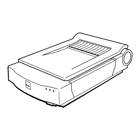
Page 10: Figure 1-1. External View
Product Description 1.1 FEATURES The GT-9000 and ES-1200C are low-cost, high-resolution (600 dpi) color image scanners for A4 or letter-size sheets. Their main features are: High resolution: 600 dpi Full-color scanning: 24-bit color Captures l@bit/pix image and converts to 8-bit High speed scanning: Monochrome Approx. -
Page 11: Table 1-1. Optional Units
Table 1-1. Optional Units Model Automatic document feeder (for GT-9000) Automatic document feeder (for ES-1200C) B813011 Transparency unit (for IBM PC) Bidirectional parallel interface board SCSI Syatem cable (25-pinto 50-pin) SCSI peripheral cable (50-pin to 50-pin) 1380818* EPSON Scanning Safari for Macintoeh... -
Page 12: Electrical Specifications
Product Description 1.2 SPECIFICATIONS This section provides specifications for the GT-9000 and ES1200C. Product type: Flatbed color image scanner Sub-scanning method: Reading head movement Photoelectric device: CCD (charge coupled device) line sensor Size of original: 216 x 297 mm (8.5 x 11.7 inches) (A40r letter size) -
Page 13: Figure 1-2. Maximum Sizeoforiginal Forscanning
1.2.2 Resistance to Electric Noise Static electricity: Panel -10 KV Metal -7 KV, 150 pF, 150 Cl 1.2.3 Environmental Conditions Temperature Operating: 5 to35degrees C(41 to95degrees F) Storage: -25 to 60 degrees C (-13 to 140 degrees F) Operating: 10t080%, nocondensation Humidity Storage: 10to857., no condensation... -
Page 14: Figure 1-3. Data Transmission Timing (Host To Scanner)
Product Description 1.3 INTERFACE SPECIFICATIONS The GT-90Ml and ES-12(M3C are equipped with the following external interfaces: Bidirectional parallel interface Parallel Interface 1.3.1 Bidirectional Bidirectional parallel interface Interface type: 8-bit parallel Data format: Synchronization: By STROBE pulse By BUSY/ACKNLG pulse Handshaking: Input/output data and interface control signals are TT’L-level compatible. - Page 15 Table 1-2. Pin Assignments for the Bidlrectionai Paraiiel Interface Pin No. Signal Name Description The STROBE pulse used to read in or send out data. Pulse STROBE width at the receiving terminal must exceed 0.5 p.s. These signals convey the Ist to 8th bits of data. HIGH level indicates a logical 1;...
-
Page 16: Scsi
Product Description 1.3.2 SCSI This section describes the SCSI interface for the GT-9000/ES-1200C. 1.3.2.1 Basic Specifications Any items not included in this service manual are in conformance with ANSI standard X3.131-1986. ANSI X3.131-1986 Interface type: The following functions are included Functions: 1. -
Page 17: Table 1-3. Commands For Scsi Interface
1.3.2.2 SCSI Commands This device uses the following group “O” p roms.sor commands: Table 1-3. Commands for SCSI Interface Command Code Description Test Unit Ready Confirm for operation Requires sense data (Note 1) Request Sense Receive Data transmission from target to initiator Send Inquiry data returned by the... -
Page 18: Table 1-5. Messages For Scsi Interface
Product Description 1.3.2.4 SCSI Messsges for SCSI Interface Table 1-5. Messages Code Message Direction Completion of ATN — Command Complete Disconnect Bus Device Reset Message Reject In/out In/out 80H-FFH Pin Assignments 1.3.2.5 SCSI Table 1-6. Pin Assignments for the SCSI Pin No. -
Page 19: Figure 1-5. Buttons And Indicators Location
Comes on when the scanner is ready to receive data. READY (green LED) Indicates that an error has occurred. ERROR (red LED) ERROR READY OPERATE EPSON e 0[ RESET OPERATE button button Figure 1-5. Buttons and Indicators Location 1.5 SELF-TEST This scanner has a built-in self-test mode to check the functions of the following parts. -
Page 20: Errors
Product Description 1.6 ERRORS When an error occurs, the scanner displays the corresponding error message using the LEDs. Command Errors An unidentified comman d is detected. Cause: The scanner ignores the cornmand or parameter. (The current Disposition: settings or the default values remain in effect.) The scanner sends a NACK and waits for the next comman d or parameter. -
Page 21: Data Transmission Protocol
Product Description 1.7 DATA TRANSMISSION PROTOCOL This section describes the data transmission protocol used by the scanner and host computer. 1.7.1 Handshaking Control Codes This section describes the control codes for the handshaking procedure. Control Codes without Parameters The host computer W&a control code. Step 1 Step 2 Illegal control code received. -
Page 22: Figure 1-8. Scanner Data Request And Monochrome Reading
Product Descrfptlon 1.7.2 Data Block Handshaking Procedure Monochrome or Color Line Sequence Reading in Block Data Transfer Mode The following handshaking procedure is required to send the control code that requests the scanner send back data. The host computer sends a control code. Step 1 The scanner sends a data block. -
Page 23: Figure 1-11. Line Data Format
Product &scriptIon Step 1 Step 2 The scanner sends another data block (red). Step 3 Step 4 Step 5 The host computer responds: The scanner sends a fiml data block. Step 6 Note: The host oomputer should not send back an ACK (06H) after rscek”ng the final data block SCANNER HOST... -
Page 24: Block Data Format
Product Description 1.7.3.1 Line Data Format information Block Header The header indicates the beginning of a data block. Refer to Section 1.6.4. status Byte counter The byte counter indicates the number of data bytes that follow the information block. The byte counter consists of 2 bytes, and the lower byte precedes the higher byte. -
Page 25: Figure 1-13. Status Byte
Product DOscridion 1.7.4 Format of Status Byte The status byte should have the format shown below. Area end flag Fatal em flag Figure 1-13. Status Byte 1. Status indicates the scanner’s current condition and error status. 2. Status accompanies the information block of the data block. 3. -
Page 26: Table 1-8. Scanner Functions
Product Description 1.8 SCANNER FUNCTIONS Table 1-8 summarizes the scanner’s functions and settings. These functions, which are explained on the following pages, are all controlled by software commands. Table 1-8. Scanner Functions Command Available Settings Function Data format 29 settings, from 50 to 1200 dpi (main scan and sub scan Output resolution resolutions can be set inde~endentlv). -
Page 27: Figure 1-14. Zoom
Product Description 1.8.2 Output Resolution The output resolution determines how many pixels, or dots, are used tbr repraiucting an image. Resolution is measured in units of dpi (dots per inch). This scanner has 29 settings: 50,60, 72,75, 80,90,100,120,133,144, 150,160,175,180,200, 216,240,300,320,360, 400,480, ~, 800,900,1200, 1600,1800, and 2400 dpi. -
Page 28: Figure 1-15. Reading Area
Product Description 1.8.4 Reading Area This function allows you to limit the scan to a specified portion of the document. Set the reading area by specifying the reading lengths, in units of dots, for both the main scan and the sub scan. The maximum selectable reading area is determined by the resolution and zoom settings. - Page 29 Product Lkscriptfon 1.8.6 Digitai Haiftoning Generally speakin~ 1 bit/pixel and 2 bits/pixel formats cannot express continuous image tones. The halftoning mode processes the scanned image data so that the data output in these formats simulates continuous tones when displayed or ptited. The halftoning mode is suitable for use with continuous tone images (such as photographs), and in conjunction with output devices that @mot handle multi-bus data for each pixel.
-
Page 30: Figure 1-16. Brightness
Product Description 1.8.7 Color Correction The color correction function can operate only when the scanner is in color line sequence mode, under which pixel color is determin ed immediately upon scanning. Four color-conection settings To disable color correction, select either color page sequence reading or are provided. -
Page 31: Scanning Mode
1.8.10 Gamma Correction This function adjusts the image input/output light intensity ratio, so that tones can be preserved when the image is output to different types of devices. This ratio is called “gamma” (y). See Figure 1-16 for a graphical representaticm of the five gamma correcdon settings. The gamma correction is set independently of other scanner functions. -
Page 32: Main Components
Product Dss@ption 1.9 MAIN COMPONENTS To simplify maintenance and repair, the main components of the GT-9000/ES-1200C have been designed for easy removal and replacement. The main components are: Main control circuit MAIN board: Power supply circuit Interface board carriage Assembly... - Page 33 Product _riPtbtl 1.9.1 B027 MAIN Contoi Board MAIN board is the main circuit board in the scanner, containing a logic arcuit and 8027 scanner engine driver circuit. The M37720SlAFP CPU (location: IC14) is used, and the following memory ICS and gate array are assigned to the memory space: Memory ICS 256K-bit SRAM: IC4/ 5/ 9/ 11...
-
Page 34: B027 Psb/Pse Power Supply Board
Product Description GT-900WES-1200C service Manual 1.9.2 B027 PSB/PSE Power Supply Board The power supply unit consists of a switching regulator arcuit, which converts the AC line voltage to the DC voltages (for example, +24 VDC, +5 VDC, +12 VDC, and –12 VDC) used by the scanner. The B027 PSB board uses a 120 V input type, and the B027 PSE board uses a 220/240 V input type. -
Page 35: Lower Case With Scanner Mechanism
Product Description 1.9.5 Lower Case with Scanner Mechanism The lower case includes the scanner mechanism compments. Among these componenk are the carriage motor, the carriage mechanism, the home position sensor, and the scanner head. 1.9.6 Upper Case The upper case includes the document glass. Figure 1-24. -
Page 36: Operating Principles
Control Circuit Block Diagram ......2-7 Outline of GT-9000/ES-1200C Operation ....2-8 Figure 2-14. -
Page 37: Engine Operations
Operating Principk3 2.1 ENGINE OPERATIONS This section describes the functions and operating principles of the GT-9000/ES-1200C engine. The engine contains a CCD image sensor with a reading resolution of 600 dpi. The engine consists of two main sections: the sensor head and the carriage-movement mechanism. - Page 38 Operating Prfncipies Photosensitive Ssction The photosensitive section converts the light energy into electrical signals and accumulates the The description below explains the process of resulting signal charge over a short term. photoelectrical conversion to change the incoming light energy into an accumulated signal charge. The equivalent circuit at left shows the operating pMaples of the photosensitive section.
- Page 39 Transmission Section This section receives the signal charge from the photosensitive section and transfers it to the output The transmission section contains two capacitors for each photodiode in the section. photosensitive section. There is only one output section, which means that signal charge for each pixel must be sent separately to the output section.
-
Page 40: Carriage Operations
Operating Ptinci@es 2.1.2 Carriage Operations Because photosensor elements are aligned and have a one-to-one correspondence with a horizontal row of pixels, no mechanical operation is required for the main scan (one horizontal reading of the original document). To read more than a single line, however, vertical movement ( also necessary. -
Page 41: Power Supply Operations
Operating Principles 2.2 POWER SUPPLY OPERATIONS The scanner can be powered by either of two power supply boards: the 120V B027 PSB board or the 220/240V B027 PSE board. The only difference in the way these boards operate is in the primary circuitry. -
Page 42: Supply Circuit Operations
Supply Circuit Operations 2.2.2 Figure 2-8 shows the power supply circuitry in block diagram form. AC power feeds into the scanner from the external power sourm. A filter circuit removes the noise. l’he AC voltage then undergoes full-wave rectification and is smoothed to produce the direct current supply voltage. This voltage is fed through a switching circuit and secondary smoothing circuit to produce a +24 supply. -
Page 43: Control Circuits
The scanner’s control circuits are implemented using a total of five boards. 2.3.1 Control Circuit Outline The scanner CPU is an 16-bit, single-chip M37720W!FP, which operates at 16 MHz. To simpli~ the circuitry, the circuits for correcting the image data signals are collected into three gate arrays. Figure 2-9 is a block diagram of the control circuitry. - Page 44 Operating Prindpks into the GT-9000/ES-12W, and ending with the output of image data to a computer. Document 10 bits/1 pixel AMP. Convertor. Scanner Head 8 bits/1 PiXd Shading Figure 2-10. Outline of GT-900WES-1200C Operation The lamps light, and the scanner reads the white standard attached to the back surface of the document glass.
- Page 45 Operating Principks Table 2-3 lists the functions of the scanner’s main elements. Table 2-3. Functions of Main Elements Location Function Element The CPU, which operates at 16 MHz, controls scanner M37720S1AFP IC14 operations. This gate array performs the following functions: .
-
Page 46: Reset Circuit
2.3.2 Reset Circuit Figure 2-11 shows the reset arcuit used to reset the controls. Immediately after power on and power off, the +5 VDC line voltage drops, and the reset IC (IC26, M51953BFP) outputs the reset signal from pin 6 (OUT port). ‘II& reset signal is then input to pin 8 (POWW of gate array to pin 6 (RS’TOUT port). -
Page 47: Carriage Motordrivecircuit
Operating Principtas Carriage Motor Drive Circuit 2.3.4 A constant current drives the carriage motor, a stepping motor that requires changes in the excitation status to generate rotation. Table 2-4 indicates the relationship between the input and output excitation phase data of the and Figure 2-14 shows the motor’s internal wiring. -
Page 48: Image Sensor Drive Circuit
Operating Principles 2.3.5 Image Sensor Drive Circuit Figure 2-15 is a block diagram of the imagesenso r drive circuit. Gate array E02A03 controls image sensor operations. The sensor receives the following control signals: the ROG signal, which drives the main sensor’s shift ekctmde; transmission pulses CKl and CK2, which transmit the signal charges (and which are described, as $1 and @2, in Section 2.1.1);... - Page 49 Operating Principles INT (Photo-signal accumulation period) ..‘ “ ’ ” signals Dummy signals Effective pixel signals Single-line output period Process Figure 2-16. Image Sensor Control Connector Scanner Head LMPI -3 Fluorescent Lamps Optional Gate Array Gate Array...
- Page 50 Chapter 3 Disassembly and Assembly Table of Contents 3.1 BEFORE BEGINNING DISASSEMBLY OR ASSEMBLY 3.1.1 Precautions..........3-1 3.1.2 TOOIS.
-
Page 51: Before Beginning Disassembly Or Assembly
Disassembly and Assemb/y 3.1 BEFORE BEGINNING DISASSEMBLY OR ASSEMBLY This section describes the precautions to take during disassembly or assembly, the tools required, and the small parts used in the scanner. 3.1.1 Precautions Before disassembling or assembling the scanner, disconnect the power supply cable from OPERATE the external AC power socket. -
Page 52: Small Parts
3.1.3 Small Parts In the following sections, abbreviations are used for small parts, such as screws and washers. Tables 3-2 and 3-3 list these abbreviations. Table 3-2. Abbreviations Used for Screw Abbreviation Part Name CP screw CPS-tite.(S-Pl) screw Plane washer 1 Table 3-3. -
Page 53: Service Shipping Check~St
Disassembly and Assembly GT-9000/ES-1200C Service Manual 3.1.4 Service Shipping Checklist Before returning the scanner to the customer, use the checldist below to ensure that it is ready for use. Table 3-4. Service Shipping Checklist Is Check Required? Category Component Item to Check... -
Page 54: Replacing The Rom
Disassembly and Assembly AND ASSEMBLY 3.2 DISASSEMBLY This section describes how to disassemble and assemble the main components of the scanner. When the procedure for installing a mmponent in the scanner is simply the reverse of the procedure for removing that component from the printer, no installation description is given. 3.2.1 Replacing the ROM 1. -
Page 55: Removing The Uppercase
Disassembly and Assembly 3.2.2 Removing the Upper Case Open the document cover, and remove the document cover. 2. Remove the and 3 fixing the upper case. 2 cosmetic (M4 x 3.4) screws 3. Remove the uppercase. Cosmetic Screw Figure 3-3. Removing the Upper Case Rev. -
Page 56: Removing The Carriage Assembly
Removing the Carriage Assembly 3.2.3 1. Remove thedocument cover and uppercase. (Refer to Section 3.2.2.) 2. Remove the harness cover. 3. Remove flat cables CN3and CN2 (through ferrite cores)on the B027MAINboard. 4. Remove the CPStite ($P1) (M3 x 6) screw and remove the spring. 5. -
Page 57: Removing The Bottom Plate
Disassembly and Assembly 3.2.4 Removing the Bottom Plate 1. Remove the document cover. (Refer to Section 3.2.2.) 2. Remove 9 CBS-tite (M3 x 6) screws and 4 CBB-tite (M3 x 10) screws. 3. Remove the bottom plate. Turn the main unit over onto a soft cloth, so that the glass will not be damaged. 3X1O) Plate Figure 3-5. -
Page 58: Removing The B027 Psb/Pse Power Supply Board
Disassembly and Assambly Removing the B027 PSBJPSE Power Supply Board 3.2.5 1. Remove thedocumentcover. (Refer to Section 3.2J2.) 2. Remove the bottom plate. (Refer to Section 3.2.4.) 3. Remove 1 CBB-tite(M4x35) screw,2CBB-tite(M3 x 10) screws, and2CBS-tite(M3 x6) screws. 4. Disconnect the 3 cables on the board, and then remove the board. Turn the main unit over onto cloth so that the glass will not be damaged. -
Page 59: Removing The B027 Main Control Board And B027 L/F Board
Disassembly and Assembly 3.2.6 Removing the B027 MAIN Control Board and B027 l/F Board Remove the document cover and uppercase. (Refer to Section 3.2.2.) 2. Remove the carriage assembly. (Refer to Section 3.2.3.) 3. Remove the bottom plate. (Refer to Section 3.2.4.) 4. - Page 60 Disassembly and Assambty Disconnect CN1O on the B027 MAIN board. 9. Remove 2 CP (M3 x 6) screws and 2 mnnector screws. 10. Remove the M127 I/F board. 11. Remove 4 CP (M3 x 10) screws. 12. Remove the B027 MAIN board. LOCK NUT Figure 3-8.
-
Page 61: Removing Thecenterrafl Andcr Motor
Disassembly and Assembly 3.2.7 Removing the Center Rail and CR Motor Remove the document cover and the uppercase. (Refer to Section 3.2.2.) Remove the carriage assembly. (Refer to Section 3.2.3.) Remove the bottom plate. (Refer to Section 3.2.4.) Disconnect comectors CN6 on the B027 MAIN board. Remove 3 CBB-tite (M4 x 12) screws and 3 CBS-tite (M3 x 6) saews. - Page 62 Disassembly and Assembly 10. Loosen the CBS-tite (M3x 6) screw. 11. Remove 2 CB (M3 x 6) screws. 12. Remove the CR motor. Figure 3-11. Removing the CR Motor Rev. A...
-
Page 63: Removing The Hpsensor
Disassembly and Assemb/y 3.2.8 Removing the HP Sensor Remove the upper case. (Refer to Section 3.2.2.) Remove the tab holding the HP sensor and discomect the comector from the HP sensor. Figure 3-12. Removing the HP Sensor 3.2.9 Removing the LED Board 1. -
Page 64: Removing The Operate Switch
Disassembly and Assembfy 3.2.10 Removing the Operate Switch 1. Remove thedocument cover and the uppercase. (Refer to Section 3.2Q.) 2. Remove thecarriageassembly. (Refer to Section 3Q3.) 3. Remove the bottom plate. (Refer to S@km3.2.4.) 4. Disconnect connector CN3 on the B027 PSB/PSE board. 5. -
Page 65: Disassembling The Carriage Assembly
Disassembly and Assembly 3.2.12 Disassembling the Carriage Assembly Remove the document cover and the uppercase. (Refer to Section 3.2.2.) 2. Remove the carriage assembly. (Refer to Section 3.2.3.) 3. Remove 2 CB (M3 x screws and 1 CBStite (M3 x 6) screw, and then remove the CR cover. 4. -
Page 66: Adjustments
Chapter 4 Adjustments No Adjustment is required in this product. -
Page 67: Troubleshooting
Chapter 5 Troubleshooting Table of Contents 5.1 OVERVIEW 5.2 SELF-DIAGNOSTIC FUNCTION 5.3 TROUBLESHOOTING Troubleshooting Abnormal Operations ......5-2 5.3.1 5.4 REPAIR OF THE POWER SUPPLY BOARD 5.5 REPAIR OF THE MAIN CONTROL BOARD... - Page 68 Troubleshooting 5.1 OVERVIEW The GT-9000/ ES-1200C has a sophisticated, built-in self-diagnostic function that reduces The following tables show motor troubleshooting time by identifying failed components. resistance ratings and sensor test points. Table 5-1. Motor Coil Resistance Motor Resistance Carriage motor I Coil resistance 4.7 Q + (25°...
- Page 69 5.3 TROUBLESHOOTING This section describes how to troubleshoot abnormal operations and repair the unit. 5.3.1 Troubleshooting Abnormal Operations The table below tells how to identify malfunctions by symptom, determine their cause, and resolve them. Each entry in the table below refers you to a more detailed troubleshooting table. Table 5-4.
- Page 70 Troubleshooting Table 5-5. OPERATE LED Does Not Light Finding Solution Step Checkpoint Cause Connect CN1 on Is connector Connector CN1 on the B027 board. disconnected? disconnected. Connect CN3 on Is connector CN3 on the Connector CN3 on the B027 board. disconnected? disconnected.
- Page 71 Table 5-5. OPERATE LED Does Not Light (Continued) Finding Solution Cause Step Disconnect connector CN3 Replace the on the B027 MAIN board and power on. Does the the scanner head. OPERATE LED come on? Disconnect connector CN2 Replace the on the B027 MAIN board Scanner head may be dead.
- Page 72 Troubleshooting Table 5-7. Carriage Does Not Move Step Checkpoint Finding Solution Cause the power on, is there With an output of +24VDC The B027 PSB/PSE board Replace the 6027 between pin 1 (+) and pin 3 may be dead. (-) for CN3 on B027 Check the Turn off the scanner and try carriage...
- Page 73 Table 5-8. Carriage Moves and Crashes Into Frame Checkpoint Finding Solution Cause Step Replace the HP HP sensor maybe bad. sensor Table 5-9. bmps Do Not Light Checkpoint Step Finding Solution Cause Is connector CN3 on the Connect CN3 on Connector CN3 on the B027 the B027 MAIN MAIN board may be...
- Page 74 Troubleshooting Table 5-11. Image Unclear Solution Cause Step Checkpoint Finding Does the scanner work after The document glass may Scanner OK. you clean the glass inside be dirty. and outside? work after Does the scanner The scanner head may be Scanner OK.
- Page 75 Troubleshooting SUPPLY BOARD 5.4 REPAIR OF THE POWER This section provides instructions for repairing a defective power supply board. Servicers who do repair to the component level (including all servicers in the US.) can ignore this section. This table describes various problems, likeIy causes, checkpoints, and solutions. The dwckpoint column provides proper waveforms, resistance values, and other values to be checked to evaluate the operation of any component that might be bad.
- Page 76 Troubleshooting 5.5 REPAIR OF THE MAIN CONTROL BOARD This section provides instructions for repairing a defective main board. It describes various problems, likely causes, checkpoints, and solutions. The checkpoint column provides proper waveforms, resistance values, and other values to checked to evaluate the operation of any component that might be bad.
- Page 77 Troubleshooting Table 5-15. Repair of the Main Controi Board (Continued) Rev. A 5-1o...
-
Page 78: Maintenance
Maintenance Chapter 6 Table of Contents 6.1 MAINTENANCE LUBRICATION List of Figures Lubrication Points........Figure 6-1. - Page 79 The scanner must be lubricated properly when it is disassembled for component replacement, or if mechnical noise exceeds a certain level. EPSON recommends only the lubricant listed in table below for this scanner. It has been tested extensively and found to comply with the requirements of the scanner mechanism.
- Page 81 Maintenance Rail Figure 6-2. Lubrication Method (1) Figure 6-3. Lubrication Method (2) Rev. A...
- Page 82 APPENDIX Table of Contents A-12 A-14 List of Figures Figure A-1. Cable Connections........A-1 Figure A-2.
- Page 83 Appendix A.1 CONNECTOR PIN ASSIGNMENTS Figure A-1 illustrates the interconnection of the primary components. Table A-1 summarizes the description and sizes of the connectors. Bidirectional Parallel i/F Optional l/F AC IN Board Board Lamps Board OPERATE Scanner Head Motor Switch Figure A-1.
- Page 84 Appendix Table A-1. Board Connector Summary Reference Pins Connector Description 9027 MAIN Control Circuit Board 11 pin I Table A-2 Table A-3 10 pin Table A-4 Connector for inverter for carriage assembly 4 pin Table A-5 LED board 4 pin Table A-6 Connector for CR motor 3 pin...
- Page 85 Appendix Table A-2. CNI Pin Assignments Description Pin No. Signal Name — Ground — +5 VDC — +12 VDC — Analog GND Table A-3. CN2 Pin Assignments Pin No. Description Signal Name Video data bit O Video data bit 1 Video data bit 2 Video data bit 3 Video data bit 4...
- Page 86 Appendix Table A-5. CN4 Pin Assignments Description Pin No. Signal Name — ERROR ERROR LED READY READY LED POWER POWER LED Table A-6. CN6 Pin Assignments Pin No. Signal Name Carriage motor phase Carriage motor phase ~ phase ~ Table A-7. CN7 Pin Assignments Description Signal Name Pin No.
- Page 87 Appendix Table A-9. CN9 Pin Assignments Description Pin No. Signal Name ID switch SCSI SCSI ID switch SCSI ID switch SCSI ID switch SCSI terminator enable +5 VDC POWER Terminator power (+5 VDC) C/D signal for SCSI — Option switch 1 Transmitted data Option switch 2 Option clock...
- Page 88 Appendix “ Figure A-3. B027 PSB Board Circuit Diagram Rev. A...
- Page 89 o ’ Figure A-4. B027 PSE Board Circuit Diagram Rev. A A-10...
- Page 90 Appendix Figure A-5. 6027 l/F Board Circuit Diagram R e v .
- Page 91 Appendix A.3 CIRCUIT BOARD COMPONENT LAYOUT — Figure A-6. B027 MAIN Board Component Layout Rev. A A-12...
- Page 92 Appendix CAUTION : .1 RISK W ELECTRIC TEST — Figure A-7. B027 PSBIPSE Board Component Layout Figure A-8. B027 l/F Board Component Layout A-13 Rev. A...
- Page 93 Appendix Table A-10. Part No. Reference Table Description PPL Name UPPER HOUSING HOUSING ASSY., UPPER LOWER HOUSING HOUSING SUB ASSY., LOWER BOTTOM PLATE BOTTOM PLATE, COVER ASSY., DOCUMENT DOCUMENT COVER FRONT FRAME FRAME FRONT FRAME, REAR REAR FRAME FLAME, SIDE, L RIGHT SIDE FRAME FLAME, SIDE, R CENTER RAIL...
- Page 94 Appendix Table A-10. Part No. Reference Table (Continued) Description PPL Name Ref. No. CARRIAGE ASSY. CARRIAGE ASSY. (SCANNER HEAD) LAMP LAMP ASSY. BOARD ASSY., INVERTOR CABLE CABLE, CR CR COVER COVER ASSY, CR CR CLAMP CLAMP, CR HOLDER, ROLLER, RAIL RAIL ROLLER HOLDER ROLLER, CARRIAGE CARRIAGE ROLLER...
- Page 95 EPSON OVERSEAS MARKETING LOCATIONS EPSON DEUTSCHLAND GmbH EPSON AMERICA, INC. 20770 Madrona Avenue, 2842 Torrance, CA 90509-2842 Phone: 0211-56030 Phone: (800) 922-8911 Fax : 0211-504-7787 Fax: (310) 782-5220 EPSON FRANCE S.A. EPSON UK LTD. Campus 100, Maylands Avenue, 68 bis, rue Marjolin 92300, Hemel Hempstead, Herts.
Need help?
Do you have a question about the GT-9000 and is the answer not in the manual?
Questions and answers