IKA KS 4000 i control Manual
Hide thumbs
Also See for KS 4000 i control:
- Operating instructions manual (85 pages) ,
- Operating instructions manual (85 pages) ,
- Operating instructions manual (84 pages)
Table of Contents
Advertisement
Advertisement
Table of Contents

Related Manuals for IKA KS 4000 i control


Summary of Contents for IKA KS 4000 i control
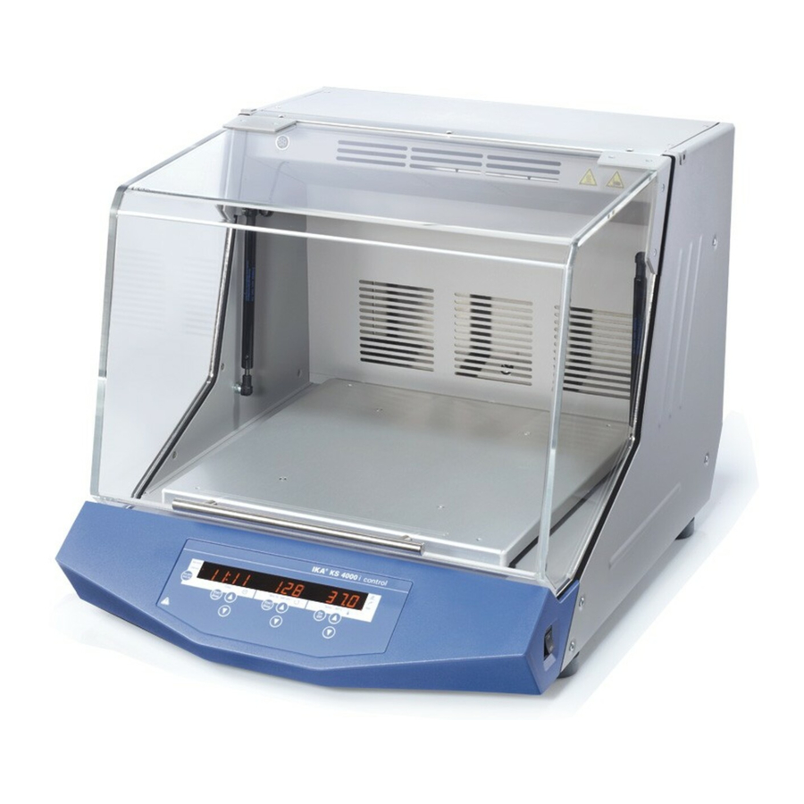
- Page 1 KS4000_1 KS 4000 i control KS 4000 ic control...
-
Page 2: Table Of Contents
The media used in the appliance may result in danger spe- Contents cific to the media and the process. This applies, for exam- ple, to shaking cultures with living cells and to aggressive Page or flammable media. Particulars as small estimated endan- Warranty germents can become, if they arise with one another in Safety instructions... - Page 3 - level of medium which is too high lower than the fire point of the media used. - biological and microbiological materials • When servicing, the wiring selected by IKA must be set up • All accessories and vessels in place for the shaking process again! must be firmly secured.
-
Page 4: Correct Use
- In the case of any damage a detailed report must be set imme- Display fields Main switch I / 0 diately (post, rail or forwarder) • Contents of package Operating mode Software KS 4000 i control KS 4000 ic control version - Shaking device - Shaking device (temperierbar) SAFE 55.5... -
Page 5: Setting The Safety Limit Values
Setting the safety limit values If the Time Start/Stop key 2 is held down while "SAFE" is dis- played, the safety limit values can be changed using the respec- tive up/down keys. Operator panel and display Display Display Display Time Speed Temperature Shift key... -
Page 6: Function Shaking
Tapping the Start/Stop keys or On/Off key starts the particular fun- Timer ctions The desired default values can be changed using the keys. The desired shaking duration is set on the operator panel of the timer using the Time up/down keys. The shift key can be used to Use the shift key 1 to switch from hour/minute mode to minu- switch from hour mode to minute mode. -
Page 7: Operating Modes
Operating modes External temperature sensor You can choose between operating modes If external temperature sensor PT1000.60 is connected to the internal slide-on receptacle, the temperature can be measured at any place in the medium. (Connector for PT1000.60) Appliance does not start up again following power outage Safety limit value for speed and temperature The temperature control of the adjustable... -
Page 8: Reset
- Close the cover and start the Temp function The cooler is connected to an external cooling unit (e.g. IKA KV - Wait until the temperature in the incubation cover has stabilised. 600) via the plug connection at the back of the appliance. The inlet... -
Page 9: Attachments
Permissible cooling agents - inlet temperature >3°C Observe the maximum permissible pressure of 1 bar! As a safeguard, we recommend using a pressure limiter (e.g. IKA C25). This is not necessary when using an IKA KV600. Accumulated condensate is drained out of the cooler through the drain hose. - Page 10 Error code Description Cause Effect Solution Er 3 Temperature inside unit too high • Permitted ambient temperature has Heating off • Switch off the unit. Allow it to cool down been exceeded and then switch on again. • Ventilation slots or fan housing •...
-
Page 11: Interface And Outputs
Error code Description Cause Effect Solution PC 1 In remote operation (PC) with • PC does not send data during the Heating off • Change the watchdog time watchdog function 1 enabled: watchdog time Motor off • Send data from the PC within the No communication between •... - Page 12 NAMUR instuctions Function • Each individual instruction including parameters and data as well as each reply are terminated with CR LF (Code: hex IN_NAME Input description name 0x0D and 0x0A) and have a maximum lenght of 80 charac- IN_PV_X Reading the real value ters.
-
Page 13: Maintenance And Cleaning
The shaker KS 4000 i control and KS 4000 ic control is mainten- controlled using the preset setpoints. An operating system ace-free. - Page 14 For materials which are not listed, please request information - shaking table from IKA. Wear the proper protective gloves during cleaning of upward remove the devices. Electrical devices may not be placed in the cleansing agent for the purpose of cleaning.
-
Page 15: Accessories
Protection at overload Temperature sensor Accessories in motorwinding Fuses on apparatus plug AS 4000.1 Universal attachment 115V T16A (Id.Nr. 37 368 00) 2x AS 4000.2 Holding bracket attachment 230V T10A (Id.Nr. 27 554 00) 2x AS 4000.3 Dish attachment Radius orit PC 1.1 Adapter Shaking motion...