Table of Contents
Advertisement
Available languages
Available languages
Advertisement
Chapters
Table of Contents

Subscribe to Our Youtube Channel
Related Manuals for Jackle inoMIG 350


Summary of Contents for Jackle inoMIG 350
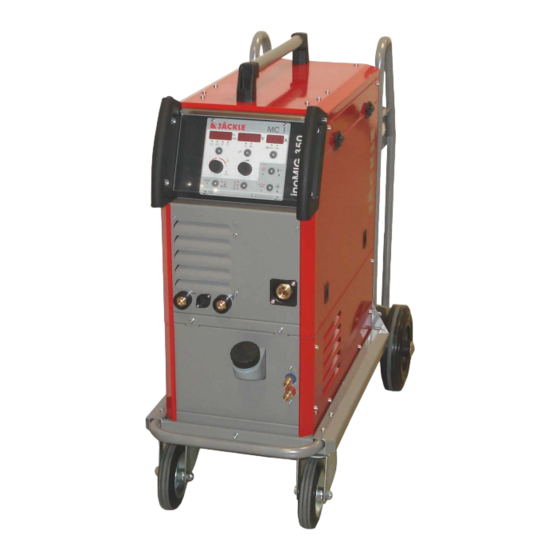
- Page 1 350/400 mit Steuerbox MC 1 / MC 2 with control box MC 1 / MC 2 Kompaktanlage / Compactunit Option mit Koffer / Option with wire feeder Sonderlichtbögen COLD/ROOT/POWER/FAST Special welding arcs COLD/ROOT/POWER/FAST Deutsch (Seite 1-26,54-64) English (Page 27-64)
-
Page 2: Inomig
Allgemeine Informationen: Diese Betriebsanleitung soll Sie dabei unterstützen, mit dem Schweißgerät effektiv und sicher zu arbeiten. Bitte lesen Sie die Anleitung vor Inbetriebnahme der Anlage gründlich durch. Die Informationen dieser Betriebsanleitung müssen dem Bedienungspersonal zugänglich gemacht werden. Die Anleitung sollte als Nachschlagewerk immer griffbereit in der Nähe der Anlage sein. Warnung: Elektromagnetische Verträglichkeit EMV (DIN EN 60974-10): Diese Klasse A Schweißeinrichtung ist nicht für den Gebrauch in Wohnbereichen vorgesehen,... - Page 3 D – 88339 Bad Waldsee Hiermit erklären wir, dass nachfolgend aufgeführte Stromquelle den Sicherheitsanforderungen der EG- Richtlinien entspricht. Bezeichnung der Anlage: Schweißstromquelle für MIG / MAG Typ der Anlage n: inoMIG 350, inoMIG 400 Einschlägige EG-Richtlinien: EMV-Richtlinie 2004/108/EG (seit 20.07.2007) Niederspannungsrichtlinie 2006/95/EG (seit 16.01.2007)
-
Page 4: Table Of Contents
Ersatzteile / spare parts .......................... 54 Schaltplan / circuit diagram ........................62 1. Kurzbeschreibung Die MIG/MAG - Schweißanlagen inoMIG 350/400 wurden für den industriellen Einsatz entwickelt. Ihre Ausstattung und Funktionsweise wurden deshalb für die professionelle Nutzung ausgelegt. Stufenlose Schweißleistungseinstellung Steuerungsfunktionen... -
Page 5: Technische Daten
350/400 2. Technische Daten Stromquelle inoMIG 350 inoMIG 400 Netzspannung, 50/60 Hz 400V, 3 Phasen (-10% / +15%) 400V, 3 Phasen (-10% / +15%) Stromaufnahme Imax = 20 A, Ieff = 13A Imax = 25 A, Ieff = 19A... -
Page 6: Sicherheitshinweise
350/400 4. Sicherheitshinweise Die Anlage ist nach den einschlägigen internationalen Normen gebaut. Die Anlage ist ausschließlich für das MIG/MAG - Schweißen bestimmt. Wie bei jedem technischen Produkt können von den Anlagen bei unsachgemäßer oder nicht bestimmungsgemäßer Nutzung Gefahren ausgehen. - Page 7 350/400 Handschuhe und Schuhe sind zu tragen, die ausreichende Isolierung bieten. Die gesamte Kleidung ist trocken zu halten. Erhöhte Vorsicht gilt in einer Umgebung mit hoher Feuchtigkeit! Alle an der Anlage angeschlossenen elektrischen Leitungen sind auf einwandfreien Zustand zu überprüfen.
- Page 8 350/400 6 Gasdruckausrüstung Gasflaschen stehen unter hohem Druck und stellen eine Gefahrenquelle dar. Beispielsweise müssen die Flaschen auf jeden Fall vor direkter Sonneneinstrahlung, vor offenem Feuer und starken Temperaturschwankungen, z. B. sehr tiefen Temperaturen geschützt werden. Der richtige Umgang mit ihnen ist unbedingt beim Gaslieferanten zu erfragen.
-
Page 9: Übersicht Steuerungsfunktionen
350/400 5. Übersicht Steuerungsfunktionen Funktionen MC 1 MC 2 ■ ■ Inverteranlage ■ ■ Handbetrieb ■ ■ Automatikbetrieb ■ ■ Lichtbogenlängenkorrektur ■ ■ Materialauswahl ■ ■ Leistung individuell einstellbar ■ ■ MIG Modus ■ ■ WIG Modus - mit Gasvorströmzeit und Slopedown Zeit einstellbar ■... -
Page 10: Bedienelemente
350/400 6. Bedienelemente Kompaktanlage: Hauptschalter (Rückseite) MC 1 Main switch Steuerbox MC 1/MC 2 l/min (Back side) Control unit MC 1/MC 2 LADEN TEST SPEICHERN Brenner Zentralanschluss Central Massebuchse torch connection Workpiece socket + Buchse Elektrode / WIG Anschluss up/down Brenner... - Page 11 350/400 Kofferanlage bzw. Koffer / Kompaktanlage: MC 1 l/min Steuerbox MC 1/MC 2 Control unit MC 1/MC 2 LADEN TEST SPEICHERN Anschluss up/down Brenner Connection up/down torch Brenner Zentralanschluss Wasserrücklauf ‘rot-heiß’ DN 5 Central water runback ‘red-hot’ DN 5 torch connection Wasservorlauf ‘blau-kalt’...
-
Page 12: Steuerung Mc 1
350/400 7. Steuerung MC 1 1 – Anzeige Display Drahtgeschwindigkeit in m/min (HAND-9), bzw. Korrektur von -3.0V bis +3.0V der Licht- bogenlänge (AUTO-9), blinkender Punkt: HOLD Funktion aktiv 2 – LED Anzeige ob 2-Takt, 4-Takt, 2-Takt - Punkten oder 2T/4T Kraterfüllen aktiv ist 3 –... -
Page 13: Steuerung Mc 2
350/400 8. Steuerung MC 2 MC 2 TEST 1 – Anzeige Display Drahtgeschwindigkeit in m/min (HAND-7), bzw. Korrektur von -3.0V bis +3.0V der Licht- bogenlänge (AUTO-7), blinkender Punkt: HOLD Funktion aktiv 4-Takt 2 – LED Anzeige ob 2-Takt, 4-Takt oder 2-Takt - Punkten aktiv ist 3 –... -
Page 14: Funktionsbeschreibung
350/400 9. Funktionsbeschreibung • 2-Takt, 4-Takt, Punkten (MC 1-2), Kraterfüllen (MC 1) Durch tippen auf die Bedientaste (3) kann zwischen 2-Takt, 4-Takt, 2-Takt Punkten (MC 1-2) und 2T/4T Kraterfüllen (MC 1) um geschalten werden. Die jeweils aktivierte Funktion wird durch die LED angezeigt. - Page 15 350/400 Funktionen Fx (MC 1) Im Ruhezustand (wenn nicht geschweißt wird): Durch kurzes antippen der Bedientaste Fx können folgende Funktionen für jede Schweißkurve individuell eingestellt werden: Betriebsart MIG: - Drossel (Cho): Stufenlose Korrektur der Schweißdrossel von ‚+15 Weicher’ bis ‚- 15 Härter’ als ‚0’ (Standard) - Startgeschwindigkeit (StS): 10 bis 100% der Schweißgeschwindigkeit...
- Page 16 350/400 Bei erneutem drücken der Bedientaste ► (11) wird immer zuerst der zuletzt geänderte Parameter angezeigt. Durch erneutes tippen auf die Taste wird zum nächsten Parameter gewechselt. Während des Schweißens: Betriebsart MIG: Während des Schweißvorganges kann durch tippen auf die Bedientaste ► die Drosselfunktion aufgerufen und geändert werden.
- Page 17 350/400 Kühlmittel – Durchflussanzeige (MC 1) Um den aktuellen Durchfluss des Kühlmittel im Kühlkreislaufsystem anzuzeigen, muss die Bedientaste l/min lang gedrückt werden. Die LED l/min leuchtet auf, und im rechten Display wird der aktuelle Wert dargestellt (z.B. 1,45). Wird der Minimumdurchfluss von 0,25l/min für länger als 5 Sekunden unterschritten, wird der Fehler ‚Err’...
-
Page 18: Inbetriebnahme / Schweißen
350/400 10. Inbetriebnahme / Schweißen Anlage aufstellen Achten Sie bei der Aufstellung auf ausreichenden Platz für Eintritt und Austritt der Kühlluft, damit die angegebene Einschaltdauer erreicht werden kann (mindestens 1m). Die Anlage sollte nach Möglichkeit nicht Nässe, Schweißspritzern und dem direkten Funkenstrahl bei Schleifarbeiten ausgesetzt werden. - Page 19 350/400 Elektrode Schweißen Vorne / front Massebuchse Workpiece socket + Buchse Elektrode / WIG + socket MMA / TIG Elektrodenhalter anschließen Elektrodenhalter wie im Bild dargestellt an die Plusbuchse anschließen. Hierbei aber immer die Polungsvorgabe des Elektrodenherstellers beachten. Drahtvorschubkoffer mit Steuerleitung muss an der Maschine eingesteckt bleiben.
- Page 20 350/400 WIG Schweißen Massebuchse Workpiece socket + Buchse Elektrode / WIG + socket MMA / TIG Start* * Brennertaster / Torch trigger - Pin 1,2 Fernbedienungsbuchse 7-polig **up/down Taster / Switch Remote control socket 7-pole down Pin 4, 5 (down),6 (up) Wasserrücklauf ‘rot-heiß’...
-
Page 21: Drahtvorschub
350/400 11. Drahtvorschub Wechseln der Drahtvorschubrolle (4) Für den verwendeten Draht muss jeweils die Drahtvorschubrolle mit der entsprechenden Nut eingesetzt werden. Zum Austauschen der Drahtvorschubrollen sind die Rändelschrauben (5) herauszudrehen. Es ist darauf zu achten, dass die Nut der Drahtvorschubrollen mit den Drahtführungsrohren (6) eine Flucht bildet. -
Page 22: Schweißbrenner Mit Display / Job - Reihenfolge
350/400 13. Schweißbrenner mit Display / Job - Reihenfolge ACHTUNG: Brenner nur bei ausgeschalteter Maschine wechseln!! Funktionen (nach Steuerbox sortiert): ■ ■ ■* ■ ■ ■ ■ ■ ■ ■ ■ ■ ■ MC 1 ■ ■ ■* ■... -
Page 23: Schweißbrennerkühlung / Kühlmittel Jpp
350/400 14. Schweißbrennerkühlung / Kühlmittel JPP Maximaler Betriebsdruck: 3,2bar Funktionsweise Die Schweißbrennerkühlung basiert auf der Funktion einer Rückkühlanlage, d.h. die Kühlflüssigkeit wird durch einen Wärmetauscher auf annähernd Raumtemperatur zurückgekühlt, mit Hilfe der vom Ventilator umgewälzten Raumluft. Wassergekühlter Brenner Ein eingebautes Wasserkühlsystem mit leise laufender Pumpe kühlt den Brenner. Der Wassertank soll annähernd voll sein. -
Page 24: Übertemperatur
350/400 16. Übertemperatur Wird durch lange Beanspruchung und sehr heiße Umgebungsbedingungen die Maschine überhitzt, wird die Maschine ab geschalten und es kann nicht mehr geschweißt werden, bis die Maschine abgekühlt ist. Dabei erscheint z.B. folgender Text im Display der Steuerung: t°C... - Page 25 350/400 Störung / Fehler Mögliche Ursache Hilfe Unregelmäßiger Drahtvorschub Draht spult schlecht von der Drahtrolle prüfen / neu einlegen Drahtspule ab Drahtaufnahmedorn läuft schwer Aufnahmedorn überprüfen falsche Drahtvorschubrolle Siehe Kapitel 10 Drahtführungsrohr bzw. Draht- Siehe Kapitel 10 führungsspirale verschmutzt/defekt Stromdüse verstopft / defekt...
-
Page 26: Materialtabelle
350/400 18. Materialtabelle Folgende Materialien sind in der Steuerung programmiert: Material Display MC Display MC Durchmesser / mm Stahl * Argon 82%, CO 18% - MIX 18 Ar82 0,8-1,0-1,2-1,6 Stahl * Argon 90%, CO 5%, O Ar90 0,8-1,0-1,2-1,6 Stahl * 0,8-1,0-1,2-1,6 CrNi 4316 –... - Page 27 350/400 PSt: Konzentrierte, druckvolle Sprühlichtbögen (Power Steel): Der POWER STEEL Lichtbogen ist ein innovativer, speziell für tiefen Einbrand und langen Stickout entwickelter Lichtbogen. Die mitgelieferten Schweißprogramme erlauben einen konzentrierten und druckvollen Lichtbogen, der überall dort eingesetzt werden kann, wo ein tiefer Einbrand, länger Stickout (Engspalt) oder eine schmälere/kleinere Schweißnahtvorbereitung gefordert ist.
- Page 28 350/400 FSt: Pulsüberlagerte Hochleistungslichtbögen (Fast Arc): Der FASTARC Lichtbogen ist ein innovativer, speziell für hohe Schweißgeschwindigkeiten bei Stahl und Nichteisenmetallen entwickelter Lichtbogen. Durch die magnetischen Einflüsse entsteht ein engerer Lichtbogen, welcher die Wärmeeinbringung in das Material reduziert, und somit den Materialverzug und die Nacharbeitung verringert.
- Page 29 350/400 Operating manual inoMIG 350 / 400 General information’s: These operating instructions are intended to ensure safe and efficient work with this welding unit. Prior to initial operation of the unit, read the instructions carefully. The information contained in this manual should be made available to all operational staff. These in structions should always be kept ready-to-hand, near the machine.
- Page 30 We declare, that below mentioned current source corresponds to the safety requirements of the recommendations. Name of unit: Welding power source for MIG / MAG Type of units: inoMIG 350, inoMIG 400 Relevant EC recommendations: EMC – Directive 2004/108/EG ( since 20.07.2007 ) Low voltage Directive 2006/95/EG ( since 16.01.2007 )
-
Page 31: Brief Description
Schaltplan / circuit diagram ........................62 20. Brief description The inoMIG 350 / 400 welding units are suited for welding thin sheet (motorcar parts) as well as extremely thick materials (industrial use). Very good results are achieved also in welding stainless steel and aluminium. -
Page 32: Technical Data
350/400 21. Technical data Power source inoMIG 350 inoMIG 400 Supply voltage, 50/60 Hz 400 V, 3-phase (-10% / +15%) 400 V, 3-phase (-10% / +15%) Drawing of current Imax = 20A, Ieff = 13A Imax = 25A, Ieff = 19A Fuse Max. -
Page 33: Safety Requirements
350/400 23. Safety requirements 1 General Information’s This welding unit has been manufactured in accordance with the relevant international standards. However, improper use or manipulation of the machine may cause hazards. The following safety instructions must be strictly observed: a) This unit is exclusively intended for the MIG/MAG welding process. - Page 34 350/400 3 Personal Protections The face and the eyes must be protected by a welder’s shield with lenses - protection category corresponding to the intensity of current. Persons working close by must also be adequately protected from arc radiation.
- Page 35 350/400 EMC and safety inspection Apart from the instructions given in this operating manual, the general safety standards, in particular the rules for prevention of accidents must be observed. The rules contain additional information’s about the prevention of radiation, smoke, combustion, electric shock, fire and explosion.
-
Page 36: Overview Control Functions
350/400 24. Overview control functions Functions MC 1 MC 2 ■ ■ Thyristor welding source ■ ■ Manual mode ■ ■ Automatic mode ■ ■ Wire feed rate tuning ■ ■ Material adjustment ■ ■ Welding power individual adjustable ■... -
Page 37: Control Elements
350/400 25. Control elements Compact unit: Hauptschalter (Rückseite) MC 1 Main switch Steuerbox MC 1/MC 2 l/min (Back side) Control unit MC 1/MC 2 LADEN TEST SPEICHERN Brenner Zentralanschluss Central Massebuchse torch connection Workpiece socket + Buchse Elektrode / WIG... - Page 38 350/400 Wire feeder unit or Compact / wire feeder unit: MC 1 l/min Steuerbox MC 1/MC 2 Control unit MC 1/MC 2 LADEN TEST SPEICHERN Anschluss up/down Brenner Connection up/down torch Brenner Zentralanschluss Wasserrücklauf ‘rot-heiß’ DN 5 Central water runback ‘red-hot’ DN 5 torch connection Wasservorlauf ‘blau-kalt’...
-
Page 39: Control Unit Mc 1
350/400 26. Control unit MC 1 1 – Display for wire speed m/min (HAND-9) or arc length correction from -3.0V to +3.0V (AUTO-9), flashing dot: HOLD Function active 2 – LED display if 2-cycle, 4-cycle, 2-cycle - spot or 2c/4c crater function is active 3 –... -
Page 40: Control Unit Mc 2
350/400 27. Control unit MC 2 MC 2 TEST 1 – Display for wire speed m/min (HAND-7) or arc length correction from -3.0V to +3.0V (AUTO-7), flashing dot: HOLD Function active 4-cycle 2 – LED display if 2-cycle, 4-cycle or 2-cycle - spot is active 3 –... -
Page 41: Functional Description
350/400 28. Functional description • 2-cycle, 4-cycle, 2-cycle spot (MC 1-2) and crater program (MC 1) By tipping on the control key (3), the box change between 2-cycle, 4-cycle, 2-cycle-spot mode (MC 1-2) and 2c/4c crater program (MC 1). The Led above shows, which function is activated. - Page 42 350/400 Function Fx (MC 1) In stand-by mode (not during welding): By tipping short on the control key ‘Fx’ the following functions can be changed for each welding curve (only in stand-by mode): Operation Mode MIG: - choke (Choc): step less correction of the welding choke from ‚+ 15 smoother’...
- Page 43 350/400 During welding: Operation mode MIG: During the welding operation, the choc function is accessed and can be modified by tapping the button ►. The left display shows Choc, in the middle display is the current value. Now, with the middle knob, the value can be changed.
- Page 44 350/400 Deleting jobs / reset to factory settings (MC 1) The control unit has 2 possibilities: 1. to delete all user jobs, display ‘rES 1 – Job’ or 2. to reset all values to factory settings, display ‘rES 2 – ALL’.
-
Page 45: Operation / Welding
350/400 29. Operation / welding - Installation of the welding unit When installing the machine, allow for sufficient space for inlet and outlet cooling air so that the rated duty cycle will be attained. The machine should not be exposed to moisture, welding spatter or spark rays caused by grinding work. - Page 46 350/400 MMA welding Vorne / front Massebuchse Workpiece socket + Buchse Elektrode / WIG + socket MMA / TIG Connection of the MMA holder Connect the electrode holder as shown in the picture to the positive terminal. Here, however, always follow the polarity specification of the electrode manufacturer.
- Page 47 350/400 TIG welding Massebuchse Workpiece socket + Buchse Elektrode / WIG + socket MMA / TIG Start* * Brennertaster / Torch trigger - Pin 1,2 Fernbedienungsbuchse 7-polig **up/down Taster / Switch Remote control socket 7-pole down Pin 4, 5 (down),6 (up) Wasserrücklauf ‘rot-heiß’...
-
Page 48: Material Table
350/400 30. Material table The following materials are in the control unit: Material Display MC Display MC Wire diameter / mm Steel * Argon 82%, CO 18% - MIX 18 Ar82 0,8-1,0-1,2-1,6 Steel * Argon 90%, CO 5%, O... - Page 49 350/400 PSt: Concentrated, pressure intensive arc (Power Steel): The POWER ARC is a modified innovative arc that has been especially developed for deep fusion penetration and long stickout. The welding programs included within the scope of supply allow a concentrated arc full of pressure that could be used everywhere, where a deeper fusion penetration, longer stickout (gap) or a narrow/smaller seam joint preparation is required.
- Page 50 350/400 FSt: Pulse superimposed high-arc (Fast Arc): The FAST ARC is a modified innovative arc that has been especially developed for high welding speeds for steel and non-ferrous metals. By means of magnetic influences, a very narrow arc reduces the heat input into the material and therefore reduces material distortion and rework.
-
Page 51: Wire Feed Unit
350/400 32. Wire feed unit 100W Motor Exchange of feed-roller (4) Depending on the wire used, the respective feed roller with matching groove must be set in. To turn or exchange the feed- rollers, remove the knurled screw (5). -
Page 52: Welding Torch With Display / Job - Sequence
350/400 34. Welding torch with Display / Job - sequence Warning: Switch off the machine for changing the torch !! Functions (sorted by the control box): ■ ■ ■* ■ ■ ■ ■ ■ ■ ■ ■ ■ ■... -
Page 53: Welding Torch Cooling / Coolant Jpp
350/400 35. Welding torch cooling / coolant JPP Maximum pressure: 3,2bar Way of functioning The welding torch coolant cooling is based on the function of a recooling plant: the cooling liquid is cooled down to approximately room temperature via heat exchanger, with the help of the room air which is circulated by the fan. -
Page 54: Over Temperature
350/400 37. Over temperature When the machine is getting hot during welding, it switched off and it can not be welded, until the machine is cooled. In over temperature conditions the following text appears in the displays: t°C - 03 - t°C = hot = temperature to high... - Page 55 350/400 Malfunction/error Cause Remedy Porous weld seam Work piece surface polluted(paint, Clean surface rust, oil, grease) No shielding gas(solenoid valve not Check / exchange solenoid valve opening) or gas tube Insufficient shielding gas Check shielding gas at pressure reducer...
-
Page 56: Ersatzteile / Spare Parts
350/400 39. Ersatzteile / spare parts Frontansicht / front view Operating manual Page 54... - Page 57 Drehknopf 28mm Turning knob 28mm 305.042.010 Deckel für Knopf Cover 28mm 305.042.011 15 Klappe rechts Movable cover right 715.032.072 16 Frontteil inoMIG 350/400 Front plate inoMIG 350/400 715.032.032 17 Isolierflansch ZA Buchse Insulating flange 455.042.011 18 Kunststoffriegel (Verschluss) Lock 303.625.007 19 Seitenbl.
- Page 58 350/400 Seitenansichten / side view Operating manual Page 56...
- Page 59 715.032.649 Flaschenhaltebügel links FG10 Bottle frame left FG10 715.032.645 46 Lüfter 12V DC (3212 JH) – inoMIG 350 Fan 12V DC (3212 JH) – inoMIG 350 450.092.005 Lüfter 24V DC – inoMIG 400 Fan 24V DC – inoMIG 400 450.119.005...
- Page 60 350/400 Koffer / wire feed case DVK 3 - 2010 Operating manual Page 58...
- Page 61 350/400 Bezeichnung Designation Nummer / Number Griff Kunststoffteil Cover plastic handle 305.235.002 Griffrohr DVK 3 - 2010 Handle metal tube DVK 3 - 2010 715.042.220 Schutzglasscheibe kleine Griffe Protecting glass small grip 705.042.260 Kunststoffgriff klein Hand grip small 305.044.002...
- Page 62 350/400 DVK 3 Ersatzteile / spare parts 4-Rollenantrieb 4-roller drive 110W/42V Operating manual Page 60...
- Page 63 350/400 Pos Bezeichnung Designation Nummer / Number Platte 4-Rollen 37-37-37 Alu Base plate 4-roller 37-37-37 Alu 455.042.028 VR-Achse M4, 8x17.3mm VR-shaft M4, 8x17.3mm 455.042.017 Gelenkachse 37.7mm Joint axis 37.7mm 455.042.111 Druckarm 37mm kpl. links Pressure arm 37mm complete left 455.042.204...
-
Page 64: Schaltplan / Circuit Diagram
Solenoid valve gas welding unit Drossel Externe Fernbedienungspotis EC1,2 Choke External remote control potentiometer Motor Motor M1,2 Ventilatoren 24V DC Fan 24V DC Elektrode Electrode JÄCKLE Stromlaufplan Name: Gerlach Circuit diagram Datum/Date: 14.04.14 inoMIG 350/400 Nr.: ino-350.0001 Schweiß- und Compakt Schneidtechnik 400V 3~50Hz... - Page 65 Fuse Externe Fernbedienungspotis EC1,2 Drossel External remote control potentiometer Choke M1,2 Ventilatoren 24V DC Fan 24V DC JÄCKLE Name: Gerlach Stromlaufplan Circuit diagram Datum/Date: 11.9.2014 inoMIG 350/400 Nr.: ino-350.0001 Schweiß- und Schneidtechnik mit Koffer / with wire feeder 400V 3~50Hz...
- Page 66 F1,2 Sicherung Steckdose Kühlgerät JÄCKLE Name: Gerlach Stromlaufplan / Circuit diagram Fuse Socket for cooling unit Datum/Date: 11.9.2014 Magnetventil inoMIG 350/400 Drossel Choke Solenoid valve gas welding unit Nr.: ino-350.0001 Compakt mit Koffer Schweiß- und M1,2 Ventilatoren 24V DC EC1,2...
- Page 68 JÄCKLE Schweiß- u. Schneidtechnik GmbH Riedweg 4 u. 9 D-88339 Bad Waldsee GERMANY www.jaeckle-sst.de info@jaeckle-sst.de Text und Abbildungen entsprechen dem technischen Stand bei Drucklegung. Irrtümer und Änderungen vorbehalten. Contents corresponding to technical standard at printing. Errors and subjects to change without notice excepted. 05/09, online: www.jaeckle-sst.de, copyrightJÄCKLE GmbH Bad Waldsee, Germany...
Need help?
Do you have a question about the inoMIG 350 and is the answer not in the manual?
Questions and answers