Chapters
Table of Contents

Related Manuals for Jackle conMIG 400


Summary of Contents for Jackle conMIG 400
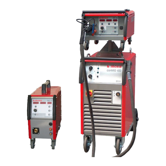
- Page 1 400 / 445 / 545 mit Steuerbox MC 3, 4, 5 oder 15 und Koffer DVK 3 oder DVK 4 with control box MC 3, 4, 5 or 15 and wire feed case DVK 3 or DVK 4 Deutsch...
- Page 3 Allgemeine Informationen: Diese Betriebsanleitung soll Sie dabei unterstützen, mit dem Schweißgerät effektiv und sicher zu arbeiten. Bitte lesen Sie die Anleitung vor Inbetriebnahme der Anlage gründlich durch. Die Informationen dieser Betriebsanleitung müssen dem Bedienungspersonal zugänglich gemacht werden. Die Anleitung sollte als Nachschlagewerk immer griffbereit in der Nähe der Anlage sein. Warnung: Elektromagnetische Verträglichkeit EMV (DIN EN 60974-10): Diese Klasse A Schweißeinrichtung ist nicht für den Gebrauch in Wohnbereichen vorgesehen,...
- Page 4 D – 88339 Bad Waldsee Hiermit erklären wir, dass nachfolgend aufgeführte Stromquelle den Sicherheitsanforderungen der EG- Richtlinien entspricht. Bezeichnung der Anlagen: Schweißstromquellen für MIG / MAG Typ der Anlagen: conMIG 400, 445, 545 Einschlägige EG-Richtlinien: EMV-Richtlinie 2004/108/EG (seit 20.07.2007) Niederspannungsrichtlinie 2006/95/EG (seit 16.01.2007)
-
Page 5: Table Of Contents
Ersatzteile / spare parts .......................... 49 Schaltpläne / circuit diagrams ....................... 62 1. Kurzbeschreibung Die MIG/MAG - Schweißanlagen conMIG 400 / 445 / 545 wurden für den industriellen Einsatz entwickelt. Ihre Ausstattung und Funktionsweise wurden deshalb für die professionelle Nutzung ausgelegt. Stufen Schweißleistungseinstellung... -
Page 6: Technische Daten
400/445/545 2. Technische Daten Stromquelle conMIG 400 conMIG 445 conMIG 545 400 V, 3 Phasen, +/- 400 V, 3 Phasen, +/- 400 V, 3 Phasen, +/- Netzspannung, 50 Hz Stromaufnahme Imax = 32 A, Ieff = 25A Imax = 35 A, Ieff = 27A... -
Page 7: Sicherheitshinweise
400/445/545 4. Sicherheitshinweise Die Anlage ist nach den einschlägigen internationalen Normen gebaut. Die Anlage ist ausschließlich für das MIG/MAG - Schweißen bestimmt. Wie bei jedem technischen Produkt können von den Anlagen bei unsachgemäßer oder nicht bestimmungsgemäßer Nutzung Gefahren ausgehen. - Page 8 400/445/545 Handschuhe und Schuhe sind zu tragen, die ausreichende Isolierung bieten. Die gesamte Kleidung ist trocken zu halten. Erhöhte Vorsicht gilt in einer Umgebung mit hoher Feuchtigkeit! Alle an der Anlage angeschlossenen elektrischen Leitungen sind auf einwandfreien Zustand zu überprüfen.
- Page 9 400/445/545 6 Gasdruckausrüstung Gasflaschen stehen unter hohem Druck und stellen eine Gefahrenquelle dar. Beispielsweise müssen die Flaschen auf jeden Fall vor direkter Sonneneinstrahlung, vor offenem Feuer und starken Temperaturschwankungen, z. B. sehr tiefen Temperaturen geschützt werden. Der richtige Umgang mit ihnen ist unbedingt beim Gaslieferanten zu erfragen.
-
Page 10: Übersicht Steuerungsfunktionen
400/445/545 5. Übersicht Steuerungsfunktionen Funktionen MC 3 MC 4 MC 5 MC15 Stufengeschaltene Schweißanlagen (conMIG) ■ ■ ■ ■ Handbetrieb ■ ■ ■ ■ ■ ■ Automatikbetrieb Drahtvorschubkorrektur ■ ■ Materialauswahl ■ ■ ■ ■ ■ ■ MIG Modus 2-Takt, 4-Takt, Punkten ■... -
Page 11: Bedienelemente
400/445/545 6. Bedienelemente MC 3 l/min Steuerbox MC 3, 4 oder 5 Control unit MC 3, 4 or 5 LADEN TEST SPEICHERN Brenner Zentralanschluss Wasserrücklauf ‘rot-heiß’ DN 5 Central water runback ‘red-hot’ DN 5 torch connection Wasservorlauf ‘blau-kalt’ DN 5 water flow ‘blue-cold’... -
Page 12: Steuerung Mc 3
400/445/545 7. Steuerung MC 3 MC 3 l/min LADEN TEST SPEICHERN 1 – Anzeige Display Drahtgeschwindigkeit in m/min, bzw. Korrektur von -50% bis +50% der Draht- geschwindigkeit, blinkender Punkt: HOLD Funktion aktiv 2 – LED Anzeige ob 2-Takt, 4-Takt, 2-Takt - Punkten oder eine Sonderfunktion aktiv ist... -
Page 13: Steuerung Mc 4
400/445/545 8. Steuerung MC 4 MC 4 TEST 1 – Anzeige Display Drahtgeschwindigkeit in m/min, bzw. Korrektur von -50% bis +50% der Draht- geschwindigkeit, blinkender Punkt: HOLD Funktion aktiv 2 – LED Anzeige ob 2-Takt, 4-Takt, 2-Takt - Punkten aktiv ist... -
Page 14: Steuerung Mc 5
400/445/545 9. Steuerung MC 5 MC 5 TEST 1 – Anzeige Display Drahtgeschwindigkeit in m/min, blinkender Punkt: HOLD Funktion aktiv 2 – LED Anzeige ob 2-Takt, 4-Takt oder 2-Takt Punkten aktiv ist 4-Takt 2-Takt Punkten 3 – Bedientaste um zwischen 2-Takt, 4-Takt, 2-Takt – Punkten durch tippen umzuschalten 4 –... -
Page 15: Steuerung Mc 15
400/445/545 10. Steuerung MC 15 MC 15 1 – Anzeige Display für die Drahtgeschwindigkeit, Einschleichgeschwindigkeit und die Drahtrückbrandzeit Während des Schweißens und im Hold (15s) wird der Schweißstrom angezeigt. z.B.: 178A 2 – Bedientaste um die Drahteinfädelfunktion zu aktivieren Der Draht wird gefördert solange die Taste gedrückt wird... -
Page 16: Funktionsbeschreibung
400/445/545 11. Funktionsbeschreibung 2-Takt, 4-Takt, Punkten, Sonderprogramme (MC 3-4)) Durch tippen auf die Bedientaste (3) kann zwischen 2-Takt, 4-Takt, 2-Takt Punkten und eventuellen Sonderfunktionen um geschalten werden. Die jeweils aktivierte Funktion wird durch die LED angezeigt. Werkstoffauswahl (Material, Gas, Drahtdurchmesser) (MC 3-4)) Durch kurzes tippen auf die Materialtaste erscheint im linken Display die Materialart (z.B. - Page 17 400/445/545 Funktionen Fx (MC 3) Im Ruhezustand (wenn nicht geschweißt wird): Durch kurzes antippen der Bedientaste Fx können folgende Funktionen für jede Schweißkurve individuell eingestellt werden: Betriebsart MIG: - Drossel (Cho): Stufenlose Korrektur der Schweißdrossel von ‚- 80 Härter’ bis ‚+ 80 Weicher’ als ‚0’ (Standard) - Startgeschwindigkeit (StS): 10 bis 100% der Schweißgeschwindigkeit...
- Page 18 400/445/545 Optionen Fx (MC 3) Hier sind untergeordnete Grundeinstellungen veränderbar. Durch langes drücken der Bedientaste Fx – länger als 1 Sekunde – werden die Optionen aufgerufen. Folgende Optionen sind veränderbar: - EC 1/2: Auswahl der Funktionen für die Fernbedienungspotentiometer (sieh nächste Seite) - Hold: Einstellung der Displayholdzeit in Sekunden (0 = unendlich bis 25s) - Zurücksetzen (Reset) der Steuerung / Speicherplätze (siehe nächster Punkt)
- Page 19 400/445/545 Drahteinfädeln Im normalen Betrieb (nicht im Job Modus! – MC 3-4) kann durch drücken der Bedientaste Drahteinfädeln’ der Draht eingefädelt werden. Er läuft solange die Taste gehalten wird. Die Einfädelgeschwindigkeit kann mit dem linken Drehknopf geändert werden. Standardmäßig wird mit 5 m/min eingefädelt.
-
Page 20: Inbetriebnahme / Schweißen
400/445/545 12. Inbetriebnahme / Schweißen Anlage aufstellen Achten Sie bei der Aufstellung auf ausreichenden Platz für Eintritt und Austritt der Kühlluft, damit die angegebene Einschaltdauer erreicht werden kann (mindestens 1m). Die Anlage sollte nach Möglichkeit nicht Nässe, Schweißspritzern und dem direkten Funkenstrahl bei Schleifarbeiten ausgesetzt werden. -
Page 21: Drahtvorschub Dvk 3 / Dvk 4
400/445/545 13. Drahtvorschub DVK 3 / DVK 4 DVK 3 – 100W Motor Wechseln der Drahtvorschubrolle (4) Für den verwendeten Draht muss jeweils die Drahtvorschubrolle mit der entsprechenden Nut eingesetzt werden. Zum Austauschen der Drahtvorschubrollen sind die Rändelschrauben (5) herauszudrehen. -
Page 22: Fernbedienungsdose (Option Bei Diesem Gerätetyp)
400/445/545 Drahtförderung im Brennerschlauchpaket Der Reibungswiderstand des Schweißdrahts in der Drahtführungsspirale vergrößert sich mit der Länge des Schlauchpakets. Das Brennerschlauchpaket sollte deshalb nicht länger als nötig gewählt werden. Bei der Verarbeitung von Aluminium-Schweißdraht empfiehlt es sich, die Drahtführungsspirale durch eine Teflon-Drahtführungs-Seele zu ersetzen. -
Page 23: Schweißbrennerkühlung / Kühlmittel Jpp
400/445/545 15. Schweißbrennerkühlung / Kühlmittel JPP Maximaler Betriebsdruck: 3,2bar Funktionsweise Die Schweißbrennerkühlung basiert auf der Funktion einer Rückkühlanlage, d.h. die Kühlflüssigkeit wird durch einen Wärmetauscher auf annähernd Raumtemperatur zurückgekühlt, mit Hilfe der vom Ventilator umgewälzten Raumluft. Wassergekühlter Brenner Ein eingebautes Wasserkühlsystem mit leise laufender Pumpe kühlt den Brenner. Der Wassertank soll annähernd voll sein. -
Page 24: Schweißbrenner Mit Display / Job - Reihenfolge
400/445/545 17. Schweißbrenner mit Display / Job - Reihenfolge ACHTUNG: Brenner nur bei ausgeschalteter Maschine wechseln!! Funktionen (nach Steuerbox sortiert): MC 3 ■ ■* ■ ■ ■ ■ ■ ■ ■ ■ MC 4 ■ ■* ■ ■ ■... -
Page 25: Übertemperatur
400/445/545 18. Übertemperatur Wird durch lange Beanspruchung und sehr heiße Umgebungsbediengungen die Maschine überhitzt, wird die Maschine abgeschalten und es kann nicht mehr geschweißt werden, bis die Maschine abgekühlt ist. Dabei erscheint z.B. folgender Text im Display der Steuerung: t°C... - Page 26 400/445/545 Draht knickt zwischen Draht- Abstand zwischen Abstand Abstand prüfen / vorschubrolle und Draht- zwischen Führungsrohr zu groß Drahtführungsrohr neu justieren führungsrohr aus Unregelmäßiger Drahtvorschub Draht spult schlecht von der Drahtrolle prüfen / neu einlegen Drahtspule ab Drahtaufnahmedorn läuft schwer Aufnahmedorn überprüfen...
-
Page 27: Materialtabelle
400/445/545 20. Materialtabelle Folgende Materialien sind standardmäßig in der Steuerung programmiert: Material Display MC Display MC Durchmesser / mm Argon 82%, CO 18% - MIX Stahl Ar82 Argon 82%, CO 18% - MIX Stahl Ar82 Argon 82%, CO 18% - MIX... - Page 28 400/445/545 Operating manual Page 25...
- Page 29 400/445/545 Operating manual conMIG 400 / 445 / 550 General information’s: These operating instructions are intended to ensure safe and efficient work with this welding unit. Prior to initial operation of the unit, read the instructions carefully. The information contained in this manual should be made available to all operational staff. These in structions should always be kept ready-to-hand, near the machine.
- Page 30 We declare, that below mentioned current source corresponds to the safety requirements of the recommendations. Name of units: Welding power sources for MIG / MAG Type of units: conMIG 400, 445, 545 Relevant EC recommendations: EMC – Directive 2004/108/EG ( since 20.07.2007 ) Low voltage Directive 2006/95/EG ( since 16.01.2007 )
-
Page 31: Brief Description
21. Brief description The conMIG 400 / 445 / 545 welding units are suited for welding thin sheet (motorcar parts) as well as extremely thick materials (industrial use). Very good results are achieved also in welding stainless steel and aluminium. -
Page 32: Technical Data
400/445/545 22. Technical data Power source conMIG 400 conMIG 445 conMIG 545 Supply voltage, 50 Hz 400 V, 3 Phase, +/- 10% 400 V, 3 Phase, +/- 10% 400 V, 3 Phase, +/- 10% Current consumption Imax = 32 A, Ieff = 25A... -
Page 33: Safety Requirements
400/445/545 24. Safety requirements 1 General Information’s This welding unit has been manufactured in accordance with the relevant international standards. However, improper use or manipulation of the machine may cause hazards. The following safety instructions must be strictly observed: a) This unit is exclusively intended for the MIG/MAG welding process. - Page 34 400/445/545 3 Personal Protections The face and the eyes must be protected by a welder’s shield with lenses - protection category corresponding to the intensity of current. Persons working close by must also be adequately protected from arc radiation.
- Page 35 400/445/545 EMC and safety inspection Apart from the instructions given in this operating manual, the general safety standards, in particular the rules for prevention of accidents must be observed. The rules contain additional information’s about the prevention of radiation, smoke, combustion, electric shock, fire and explosion.
-
Page 36: Overview Control Functions
400/445/545 25. Overview control functions Functions MC 3 MC 4 MC 5 MC15 Step switched welding source (conMIG) ■ ■ ■ ■ Manual mode ■ ■ ■ ■ ■ ■ Automatic mode Wire feed rate tuning ■ ■ Material adjustment ■... -
Page 37: Control Elements
400/445/545 26. Control elements MC 3 l/min Steuerbox MC 3, 4 oder 5 Control unit MC 3, 4 or 5 LADEN TEST SPEICHERN Brenner Zentralanschluss Wasserrücklauf ‘rot-heiß’ DN 5 Central water runback ‘red-hot’ DN 5 torch connection Wasservorlauf ‘blau-kalt’ DN 5 water flow ‘blue-cold’... -
Page 38: Control Unit Mc 3
400/445/545 27. Control unit MC 3 MC 3 l/min LADEN TEST SPEICHERN 1 – Display for wire speed (m/min) or wire speed correction from -50% to +50% flashing dot: HOLD Function active 2 – LED display if 2-cycle, 4-cycle, 2-cycle - spot or a special function is active... -
Page 39: Control Unit Mc 4
400/445/545 28. Control unit MC 4 MC 4 TEST 1 – Display for wire speed (m/min) or wire speed correction from -50% to +50% flashing dot: HOLD Function active 2 – LED display if 2-cycle, 4-cycle or 2-cycle - spot is active... -
Page 40: Control Unit Mc 5
400/445/545 29. Control unit MC 5 MC 5 TEST 1 – Display for wire speed (m/min) or wire speed correction from -50% to +50% flashing dot: HOLD Function active 2 – LED display if 2-cycle, 4-cycle or 2-cycle - spot is active... -
Page 41: Control Unit Mc 15
400/445/545 30. Control unit MC 15 MC 15 1 – Display for the wire speed, wire soft start and wire burn back value During welding and in hold function (15s) the display shows the welding current. e.g. 178A 2 – Control key to activate the wire inch function Press and hold the button down for wire inch. -
Page 42: Functional Description
400/445/545 31. Functional description 2-cycle, 4-cycle, spot, special program (MC 3-4) By tipping on the control key (3), the box change between 2-cycle, 4-cycle, 2-cycle-spot mode or a special program. The Led above shows, which function is activated. Material selection (material, gas, wire diameter) (MC 3-4) With a short tip on the control key ‘material’, the actual material appears in the 3 displays. - Page 43 400/445/545 The values can be changed by rotating the left knob. If the value is not changed for more then 2 seconds, the value will be stored. During welding: Operation mode MIG: During the welding operation, the choc function is accessed and can be modified by tapping the button Fx.
- Page 44 400/445/545 (the middle display shows the diameter of the cable: e.g. 35mm²) e.g.: 12 = complete length of all cables 12m (maximum 40m) Note: The torch type and the cable length must be set exactly, otherwise the machine is not welding correctly.
-
Page 45: Material Table
400/445/545 To assign a function to a potentiometer, press Fx until ‘EC 1’ appears in the display. Once more tipping on the key Fx to select EC 2. With the middle rotating knob, select the function as described above (in the middle display). -
Page 46: Operation / Welding
400/445/545 33. Operation / welding - Installation of the welding unit When installing the machine, allow for sufficient space for inlet and outlet cooling air so that the rated duty cycle will be attained. The machine should not be exposed to moisture, welding spatter or spark rays caused by grinding work. -
Page 47: Wire Feed Unit Dvk 3 / Dvk 4
400/445/545 34. Wire feed unit DVK 3 / DVK 4 DVK 3 – 100W Motor Exchange of feed-roller (4) Depending on the wire used, the respective feed roller with matching groove must be set in. To turn or exchange the feed- rollers, remove the knurled screw (5). -
Page 48: Remote Control Socket (Option For This Type Of Machines)
400/445/545 Wire conveying inside the torch hose pack Friction resistance of the welding wire inside the wire guide spiral increases in proportion to the length of the hose pack. Therefore, the torch hose pack shouldn’t be any longer than necessary. -
Page 49: Welding Torch Cooling / Coolant Jpp
400/445/545 37. Welding torch cooling / coolant JPP Maximum pressure: 3,2bar Way of functioning The circulation water cooling is based on the function of a recooling plant: the cooling liquid is cooled down to approximately room temperature via heat exchanger, with the help of the room air which is circulated by the fan. -
Page 50: Welding Torch With Display / Job - Sequence
400/445/545 39. Welding torch with Display / Job - sequence Warning: Switch off the machine for changing the torch !! Functions (sorted by the control box): MC 3 ■ ■* ■ ■ ■ ■ ■ ■ ■ ■ MC 4 ■... -
Page 51: Trouble - Shooting
400/445/545 40. Trouble - shooting Any remedial action to defective electrical equipment must be carried out by a qualified electrician! Malfunction/error Cause Remedy Display Machine overheated Machine to cool down with a T°C – 01/02/03 – hot (See Point 33) -
Page 52: Ersatzteile / Spare Parts
400/445/545 41. Ersatzteile / spare parts Frontansicht / front view Oben / top view Operating manual Page 49... - Page 53 Across handle K2010 715.044.339 Kunststoffgriff groß Plastic hand grip big 305.044.001 Feinstufenschalter (12) conMIG 400 Fine weld grade switch (12) conMIG 400 440.020.041 Pfeildrehknopf (4XM1-12) Rotary knob with arrow (4XM1-12) 440.220.051 Feinstufenschalter (12) conMIG 445 Fine weld grade switch (12) conMIG 445 440.225.004...
- Page 54 400/445/545 Seitenansicht links / sideview left Operating manual Page 51...
- Page 55 Wheel 300mm (conMIG 445/545) 301.300.001 Starlockkappe 25mm Star lock cap 25mm 301.025.010 Feinstufenschalter (12) conMIG 400 Fine weld grade switch (12) conMIG 400 440.020.041 Feinstufenschalter (12) conMIG 445 Fine weld grade switch (12) conMIG 445 440.225.004 Feinstufenschalter (12) conMIG 545 Fine weld grade switch (12) conMIG 545 440.432.100...
- Page 56 400/445/545 Seitenansicht rechts / sideview right Operating manual Page 53...
- Page 57 Capacitor 2µF (conMIG 400) 453.450.003 Kondensator 5µF (conMIG 445/545) Capacitor 5µF (conMIG 445/545) 453.400.013 Lüfterblech 300 (conMIG 400) Fan mounting plate (conMIG 400) 715.044.310 Lüfterblech 350 (conMIG 445/545) Fan mounting plate (conMIG 445/545) 715.044.307 Lüfter 300mm (conMIG 400) Fan 300mm (conMIG 400) 450.300.020...
- Page 58 400/445/545 Koffer / wire feed case DVK 3 - 2010 Operating manual Page 55...
- Page 59 400/445/545 Bezeichnung Designation Nummer / Number Griff Kunststoffteil Cover plastic handle 305.235.002 Griffrohr DVK 3 - 2010 Handle metal tube DVK 3 - 2010 715.042.220 Schutzglasscheibe kleine Griffe Protecting glass small grip 705.042.260 Kunststoffgriff klein Hand grip small 305.044.002...
- Page 60 400/445/545 DVK 3- Ersatzteile 4-Rollenantrieb / spare parts 4-roller drive - 110W/42V Pos Bezeichnung Designation Nummer / Number Platte 4-Rollen 37-37-37 Alu Base plate 4-roller 37-37-37 Alu 455.042.028 VR-Achse M4, 8x17.3mm VR-shaft M4, 8x17.3mm 455.042.017 Gelenkachse 37.7mm Joint axis 37.7mm 455.042.111...
- Page 61 400/445/545 Koffer / wire feed case DVK 4 - 2010 Operating manual Page 58...
- Page 62 400/445/545 Bezeichnung Designation Nummer / Number Klapphaube DVK 4 – 2010 Flap Case DVK 4 – 2010 715.013.210 Handgriff quer DVK 4 -2010 Across handle DVK 4 – 2010 715.013.127 Kunststoffgriff klein Hand grip small 305.044.002 Schraube Torx PT60 Screw Torx PT60 271.060.001...
- Page 63 400/445/545 DVK 4 Ersatzteile / spare parts 4-Rollenantrieb 4-roller drive 140W/42V Bezeichnung Designation Nummer / Number Kohlebürste 140W Carbon brush 140W 457.140.001 Bürstendeckel 140W Brushing cover 140W 457.140.002 Stator 140W Stator 140W 457.140.046 Ösenschraube M8 Eyelet bolt M8 457.140.004...
- Page 64 400/445/545 Sicherungsring I 32 x 1,5 Securing ring I 32 x 1,5 D472 I32x1,5 Nylonzahnrad, schrägverzahnt Nylon gear wheel, helical gearing 457.140.019 Keil 4x5 mm Wedge 4x5 mm 457.140.020 Zahnradwelle Long face pinion 457.140.021 Sicherungsring I 40 x 1,75...
-
Page 65: Schaltpläne / Circuit Diagrams
T-down Flachband Push-pull MC - CHO T-up T-BT +24V Brenner EC1 EC2 +10V U-Leitspg. 1 Drahtvorschubkoffer DVK U-Leitspg. 2 Werkstück I-Ist Name: Gerlach JÄCKLE Stromlaufplan U-Ist Datum: 17.02.12 conMIG 400 Fernbedienungs - Optionen Nr.: conMIG.001 Schweiß- und Schneidtechnik 400V 3~50Hz... - Page 66 T-BT +24V Torch EC1 EC2 +10V U-voltage 1 wire feed case DVK U-voltage 2 Workpiece I-actual Name: Gerlach JÄCKLE Circuit diagram U-actual Datum: 17.02.12 conMIG 400 Remote control - options Nr.: conMIG.001 Schweiß- und FB socket 17-pole Schneidtechnik 400V 3~50Hz...
- Page 67 Steuerbox MC 3, 4 oder 5 Stromquelle conMIG Platine MC - DVV Platine MC - AREM Platine I-Sense (Strommessung) Platine MC - CHO (Drosselregelung) Durchflußmesser Kühlwasser C1, C2 Kondensator 0,1µF/630V Primärsicherung H1,H2 Kontrollleuchte Netz Netzschütz Drossel Drahtvorschubmotor Ventilator Wasserpumpe Hauptschalter Stufenschalter grob Stufenschalter fein Zwischen-...
- Page 68 Control unit MC 3,4 or 5 Power source conMIG PCB MC - DVV PCB MC - AREM PCB I-Sense (current measurement) PCB MC - CHO (choke regulation) water flow meter C1, C2 capacitor 0,1µF/630V Primary fuse H1,H2 Controllamps main Main contactor Choke Wire feed motor Water pump...
- Page 69 Steuerbox MC 3, 4 oder 5 Stromquelle conMIG Platine MC - DVV Platine MC - AREM Platine I-Sense (Strommessung) Platine MC - CHO (Drosselregelung) Durchflußmesser Kühlwasser C1, C2 Kondensator 0,1µF/630V Primärsicherung H1,H2 Kontrollleuchte Netz Netzschütz Drossel Drahtvorschubmotor M2-1 Ventilator Wasserpumpe Hauptschalter Stufenschalter grob Stufenschalter fein...
- Page 70 Control unit MC 3,4 or 5 Power source conMIG PCB MC - DVV PCB MC - AREM PCB I-Sense (current measurement) PCB MC - CHO (choke regulation) water flow meter C1, C2 capacitor 0,1µF/630V Primary fuse H1,H2 Controllamps main Main contactor Choke Wire feed motor M2-1...
- Page 72 JÄCKLE Schweiß- u. Schneidtechnik GmbH Riedweg 4 u. 9 D-88339 Bad Waldsee GERMANY www.jaeckle-sst.de info@jaeckle-sst.de Text und Abbildungen entsprechen dem technischen Stand bei Drucklegung. Irrtümer und Änderungen vorbehalten. Contents corresponding to technical standard at printing. Errors and subjects to change without notice excepted. 05/09, online: www.jaeckle-sst.de, copyrightJÄCKLE GmbH Bad Waldsee, Germany...
Need help?
Do you have a question about the conMIG 400 and is the answer not in the manual?
Questions and answers