
Related Manuals for Jackle MIG 325


Summary of Contents for Jackle MIG 325
- Page 1 MIG 325,405,505 mit Steuerbox MC 4,5,15 with control box MC 4,5,15 Deutsch (Seite 1-18,37-43) English (Page 19-43)
- Page 3 Allgemeine Informationen: Diese Betriebsanleitung soll Sie dabei unterstützen, mit dem Schweißgerät effektiv und sicher zu arbeiten. Bitte lesen Sie die Anleitung vor Inbetriebnahme der Anlage gründlich durch. Die Informationen dieser Betriebsanleitung müssen dem Bedienungspersonal zugänglich gemacht werden. Die Anleitung sollte als Nachschlagewerk immer griffbereit in der Nähe der Anlage sein. Warnung: Elektromagnetische Verträglichkeit EMV (DIN EN 60974-10): Diese Klasse A Schweißeinrichtung ist nicht für den Gebrauch in Wohnbereichen vorgesehen,...
- Page 4 MIG 325,405,505 EG-KONFORMITÄTSERKLÄRUNG Hersteller: Jäckle Schweiß- und Schneidtechnik GmbH Riedweg 4+9 D – 88339 Bad Waldsee Hiermit erklären wir, dass nachfolgend aufgeführte Stromquelle den Sicherheitsanforderungen der EG- Richtlinien entspricht. Bezeichnung der Anlagen: Schweißstromquelle für MIG / MAG Typ der Anlagen: MIG 325,405,505 Einschlägige EG-Richtlinien:...
-
Page 5: Table Of Contents
MIG 325,405,505 Inhalt Inhaltsverzeichnis Seite 1. Kurzbeschreibung ......................3 2. Technische Daten ......................4 3. Umgebungsbedingungen ....................4 4. Sicherheitshinweise ......................5 5. Übersicht Steuerungsfunktionen ................... 8 6. Bedienelemente ....................... 8 7. Steuerung MC 15 ......................9 8. Steuerung MC 4 ......................10 9. -
Page 6: Kurzbeschreibung
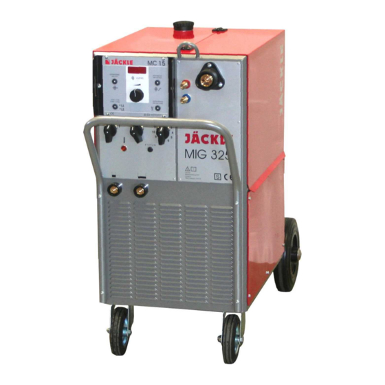
MIG 325,405,505 1. Kurzbeschreibung Die MIG/MAG - Schweißanlagen MIG 325,405,505 eignen sich zum Schweißen von Dünnblech (Kfz) bis zu dicksten Materialien. Auch beim Schweißen von Edelstahl und Aluminium werden sehr gute Ergebnisse erzielt. Schweißstufeneinstellung MIG 325,405,505: 24 Stufen Steuerungsfunktionen Siehe MC Boxen Beschreibung. -
Page 7: Technische Daten
MIG 325,405,505 2. Technische Daten Stromquelle MIG 325 MIG 405 MIG 505 Netzspannung, 50/60 Hz 400 V, 3 Phasen 400 V, 3 Phasen 400 V, 3 Phasen Max. Stromaufnahme 24 A 32 A 45 A Sicherung 20 A träge 25 A träge 32 A träge... -
Page 8: Sicherheitshinweise
MIG 325,405,505 4. Sicherheitshinweise Die Anlage ist nach den einschlägigen internationalen Normen gebaut. Die Anlage ist ausschließlich für das MIG/MAG - Schweißen bestimmt. Wie bei jedem technischen Produkt können von den Anlagen bei unsachgemäßer oder nicht bestimmungsgemäßer Nutzung Gefahren ausgehen. - Page 9 MIG 325,405,505 Erhöhte Vorsicht gilt in einer Umgebung mit hoher Feuchtigkeit! Alle an der Anlage angeschlossenen elektrischen Leitungen sind auf einwandfreien Zustand zu überprüfen. Warnung: Blanke Stellen ohne bzw. mit schadhafter Isolierung sind lebensgefährlich. Beschädigte Kabel bzw. Schlauchpakete sofort ersetzen! Beim Wechsel der Brennerteile die Anlage am Hauptschalter außer Betrieb setzen.
- Page 10 MIG 325,405,505 6 Gasdruckausrüstung Gasflaschen stehen unter hohem Druck und stellen eine Gefahrenquelle dar. Beispielsweise müssen die Flaschen auf jeden Fall vor direkter Sonneneinstrahlung, vor offenem Feuer und starken Temperaturschwankungen, z. B. sehr tiefen Temperaturen geschützt werden. Der richtige Umgang mit ihnen ist unbedingt beim Gaslieferanten zu erfragen.
-
Page 11: Übersicht Steuerungsfunktionen
MIG 325,405,505 5. Übersicht Steuerungsfunktionen MC 15 MC 4 MC 5 Funktionen Stufengeschaltene Schweißanlagen (conMIG) ■ ■ ■ Handbetrieb ■ ■ ■ Automatikbetrieb ■ Drahtvorschubkorrektur ■ Materialauswahl ■ MIG Modus ■ ■ ■ 2-Takt, 4-Takt ■ ■ ■ Punkten ■... -
Page 12: Steuerung Mc 15
MIG 325,405,505 7. Steuerung MC 15 MC 15 1 – Anzeige Display für die Drahtgeschwindigkeit, Einschleichgeschwindigkeit und die Drahtrückbrandzeit Während des Schweißens und im Hold (15s) wird der Schweißstrom angezeigt. z.B.: 178A 2 – Bedientaste um die Drahteinfädelfunktion zu aktivieren Der Draht wird gefördert solange die Taste gedrückt wird... -
Page 13: Steuerung Mc 4
MIG 325,405,505 8. Steuerung MC 4 MC 4 TEST 1 – Anzeige Display Drahtgeschwindigkeit in m/min, bzw. Korrektur von -50% bis +50% der Draht- geschwindigkeit, blinkender Punkt: HOLD Funktion aktiv 2 – LED Anzeige ob 2-Takt, 4-Takt, 2-Takt - Punkten aktiv ist... -
Page 14: Steuerung Mc 5
MIG 325,405,505 9. Steuerung MC 5 MC 5 TEST 1 – Anzeige Display Drahtgeschwindigkeit in m/min, blinkender Punkt: HOLD Funktion aktiv 2 – LED Anzeige ob 2-Takt, 4-Takt oder 2-Takt Punkten aktiv ist 4-Takt 2-Takt Punkten 3 – Bedientaste um zwischen 2-Takt, 4-Takt, 2-Takt – Punkten durch tippen umzuschalten 4 –... -
Page 15: Funktionsbeschreibung
MIG 325,405,505 10. Funktionsbeschreibung 2-Takt, 4-Takt, Punkten Durch tippen auf die Bedientaste, kann zwischen 2-Takt, 4-Takt, 2-Takt Punkten umgeschalten werden. Die jeweils aktivierte Funktion wird durch die LED angezeigt. Werkstoffauswahl (Material, Gas, Drahtdurchmesser) (MC 4) Durch kurzes tippen auf die Materialtaste, erscheint im linken Display die Materialart (z.B. Stahl), im mittleren Display das Gas (z.B. -
Page 16: Materialtabelle
MIG 325,405,505 Gastest (MC 4-5) Um das Gasventil zu öffnen, muss die Bedientaste ‚Gastest’ länger als 1 Sekunde gedrückt werden. Danach wird das Gasventil für 20 Sekunden geöffnet, schließt danach automatisch, oder wenn während dieser 20 Sekunden die Bedientaste erneut betätigt wird. -
Page 17: Drahtvorschub
MIG 325,405,505 12. Drahtvorschub 140W Motor Vierrollenantrieb Vier untereinander verzahnte Drahtvorschubrollen sorgen für einen sicheren Transport des Schweißdrahts. Für den verwendeten Draht muss jeweils die Drahtvorschubrolle mit der entsprechenden Nut eingesetzt werden. Jede Drahtvorschubrolle ist zweiseitig nutzbar. Zum Drehen bzw. Austauschen der Drahtvorschubrollen sind die Inbusschrauben (4) herauszudrehen. -
Page 18: Inbetriebnahme
MIG 325,405,505 13. Inbetriebnahme Anlage aufstellen Achten Sie bei der Aufstellung auf ausreichenden Platz für Eintritt und Austritt der Kühlluft, damit die angegebene Einschaltdauer erreicht werden kann. Die Anlage sollte nach Möglichkeit nicht Nässe, Schweißspritzern und dem direkten Funkenstrahl bei Schleifarbeiten ausgesetzt werden. -
Page 19: Schweißbrenner Mit Display (Option)
MIG 325,405,505 15. Schweißbrenner mit Display (Option) ACHTUNG: Brenner nur bei ausgeschalteter Maschine wechseln!! Funktionen (nach Steuerbox sortiert): MC 4 ■ ■* ■ ■ ■ ■ MC 5 ■* ■ ■ ■ ■ * Diese Funktion ist während des Schweißens aktiv! -
Page 20: Pflege Und Sicherheitsprüfung
MIG 325,405,505 16. Pflege und Sicherheitsprüfung Vor allen Pflege- und Wartungsarbeiten Netzstecker ziehen! Die Anlage ist weitgehend wartungsfrei. Folgende Wartungsarbeiten sollten jedoch durchgeführt werden: Stromdüse und Gasdüse regelmäßig von Schweißspritzern und Verunreinigungen säubern. Düsen nach Reinigung mit Trennmittel versehen, um die Spritzerhaftung zu verringern. -
Page 21: Störungen, Fehler, Ursache Und Beseitigung
MIG 325,405,505 19. Störungen, Fehler, Ursache und Beseitigung Fehler und Defekte an der elektrischen Anlage dürfen nur von einer Elektrofachkraft behoben werden. Störung / Fehler Mögliche Ursache Hilfe Fehleranzeige Maschine überhitzt Maschine mit laufendem Lüfter T°C – 01/02/03 – hot abkühlen lassen... - Page 22 MIG 325,405,505 Operating manual MIG 325,405,505 General information’s: These operating instructions are intended to ensure safe and efficient work with this welding unit. Prior to initial operation of the unit, read the instructions carefully. The information contained in this manual should be made available to all operational staff. These in structions should always be kept ready-to-hand, near the machine.
- Page 23 We declare, that below mentioned current source corresponds to the safety requirements of the recommendations. Name of units: Welding power source for MIG / MAG Type of units: MIG 325, 405, 505 Relevant EC recommendations: EMC – Directive 2004/108/EG ( since 20.07.2007 ) Low voltage Directive 2006/95/EG ( since 16.01.2007 )
-
Page 24: Brief Description
Schaltpläne / circuit diagrams ....................... 43 20. Brief description The MIG 325,405,505 welding units are suited for welding thin sheet (motorcar parts) as well as extremely thick materials. Very good results are achieved also in welding stainless steel and aluminium. -
Page 25: Technical Data
MIG 325,405,505 21. Technical data Power source MIG 325 MIG 405 MIG 505 Supply voltage, 50 Hz 400 V, 3-phase 400 V, 3-phase 400 V, 3-phase Max. current consumption 24 A 32 A 45 A Fuse 20 A slow 25 A slow 32 A slow Max. -
Page 26: Safety Requirements
MIG 325,405,505 23. Safety requirements 1 General Information’s This welding unit has been manufactured in accordance with the relevant international standards. However, improper use or manipulation of the machine may cause hazards. The following safety instructions must be strictly observed: a) This unit is exclusively intended for the MIG/MAG welding process. - Page 27 MIG 325,405,505 3 Personal Protection The face and the eyes must be protected by a welder’s shield with lenses - protection category corresponding to the intensity of current. Persons working close by must also be adequately protected from arc radiation.
- Page 28 MIG 325,405,505 EMC and safety inspection Apart from the instructions given in this operating manual, the general safety standards, in particular the rules for prevention of accidents must be observed. The rules contain additional information’s about the prevention of radiation, smoke, combustion, electric shock, fire and explosion.
-
Page 29: Overview Control Functions
MIG 325,405,505 24. Overview control functions Functions MC 15 MC 4 MC 5 Step switched welding source (conMIG) ■ ■ ■ Manual mode ■ ■ ■ Automatic mode ■ Wire feed rate tuning ■ Material adjustment ■ MIG mode ■... -
Page 30: Control Unit Mc 15
MIG 325,405,505 26. Control unit MC 15 MC 15 1 – Display for the wire speed, wire soft start and wire burn back value During welding and in hold function (15s) the display shows the welding current. e.g. 178A 2 – Control key to activate the wire inch function Press and hold the button down for wire inch. -
Page 31: Control Unit Mc 4
MIG 325,405,505 27. Control unit MC 4 MC 4 TEST 1 – Display for wire speed (m/min) or wire speed correction from -50% to +50% flashing dot: HOLD Function active 2 – LED display if 2-cycle, 4-cycle or 2-cycle - spot is active... -
Page 32: Control Unit Mc 5
MIG 325,405,505 28. Control unit MC 5 MC 5 TEST 1 – Display for wire speed (m/min) or wire speed correction from -50% to +50% flashing dot: HOLD Function active 2 – LED display if 2-cycle, 4-cycle or 2-cycle - spot is active... -
Page 33: Functional Description
MIG 325,405,505 29. Functional description 2-cycle, 4-cycle, spot By tipping on the control key, the box change between 2-cycle, 4-cycle, 2-cycle-spot mode. The Led above shows, which function is activated. Material selection (material, gas, wire diameter) (MC 4) With a short tip on the control key ‘material’, the actual material appears in the 3 displays. In the left display is the material (e.g. -
Page 34: Material Table
MIG 325,405,505 Gas test (MC 4-5) To open the gas valve, press the control key ‘gas test’ for more then 1 second. The gas valve is now open for 20 seconds. After this time the gas valve closes automatically. To close the gas valve earlier, press the control key again. -
Page 35: Wire Feed Unit
MIG 325,405,505 31. Wire feed unit 140W Motor Four interlocked wire feed rollers ensure safe feeding of the weld wire. Depending on the wire used, the respective feed roller with matching groove must be set in. All feed-rollers are intended for two-sided use. To turn or exchange the feed-rollers, remove the hex socket screws (4). -
Page 36: Operation / Welding
MIG 325,405,505 32. Operation / Welding - Installation of the welding unit When installing the machine, allow for sufficient space for inlet and outlet cooling air so that the rated duty cycle will be attained. The machine should not be exposed to moisture, welding spatter or spark rays caused by grinding work. -
Page 37: Welding Torch With Display (Option)
MIG 325,405,505 34. Welding torch with Display (option) Warning: Switch off the machine for changing the torch !! Functions (sorted by the control box): MC 4 ■ ■* ■ ■ ■ ■ MC 5 ■* ■ ■ ■ ■ * This function is active during welding! -
Page 38: Maintenance And Safety Check
MIG 325,405,505 35. Maintenance and safety check Disconnect mains prior to any service and maintenance work! The welding unit is, on principle, maintenance-free. However, make it a rule to carry out the following work: Clean current contact tip and gas nozzle regularly, removing welding spatter and other impurities. Add Anti-Stick agent on nozzles after cleaning to reduce undesirable spatter adhesion. -
Page 39: Trouble - Shooting
MIG 325,405,505 38. Trouble - shooting Any remedial action to defective electrical equipment must be carried out by a qualified electrician! Malfunction/error Cause Remedy Error Display Engine overheated Machine to cool down with a T°C – 01/02/03 – hot (See Point 33) -
Page 40: Ersatzteile / Spare Parts
MIG 325,405,505 39. Ersatzteile / spare parts Frontansicht / frontview Operating manual Page 37... - Page 41 MIG 325,405,505 Bezeichnung Designation Nummer / Number Haube – Wasser (Option) Case top – water (Option) 715.055.013 Haube - Gas Case top - gas 715.055.017 Schutzrahmen MC Protection frame MC 715.011.071 Steuerbox MC 15 Control box MC 15 851.044.010 Steuerbox MC 4 Control box MC 4 851.044.004...
- Page 42 MIG 325,405,505 Seitenansichten / sideview Operating manual Page 39...
- Page 43 454.000.027 feed Wärmetauscher einzeln (Option) Heat exchanger solo (Option) 309.361.002 Schweißtrafo MIG 325 kpl. 722.006.006 Welding transformer MIG 325 cpl. Schweißtrafo MIG 405 kpl. 722.006.008 Welding transformer MIG 405 cpl. Schweißtrafo MIG 505 kpl. 722.006.016 Welding transformer MIG 505 cpl.
- Page 44 MIG 325,405,505 Ersatzteile / spare parts 4-Rollenantrieb 4-roller drive 140W/42V Bezeichnung Designation Nummer / Number Kohlebürste 140W Carbon brush 140W 457.140.001 Bürstendeckel 140W Brushing cover 140W 457.140.002 Stator 140W Stator 140W 457.140.046 Ösenschraube M8 Eyelet bolt M8 457.140.004 Feder D10 x 0,5 x 70 mm Feather D10 x 0,5 x 70 mm 457.140.005...
- Page 45 MIG 325,405,505 Kugellager 10x26x8 mm, 6000 2RZ Ball bearing 10x26x8 mm, 6000 2RZ 285.000.002 Sicherungsring I 32 x 1,5 Securing ring I 32 x 1,5 D472 I32x1,5 Nylonzahnrad, schrägverzahnt Nylon gear wheel, helical gearing 457.140.019 Keil 4x5 mm Wedge 4x5 mm 457.140.020...
-
Page 46: Schaltpläne / Circuit Diagrams
Wasserdruckschalter (Option) water pressure switch (option) Gleichrichter Schweißtrafo Werkstück rectifier welding transformer workpiece Magnetventil Steuertrafo solenoid valve auxiliary transformer JÄCKLE Name: Gerlach Stromlaufplan Date: Datum: 12.02.17 circuit diagram Brenner Nr.: conMIG325-V1.1 Schweiß- und torch Schneidtechnik MIG 325/405/505 - MC 400V 3~50Hz... - Page 48 JÄCKLE Schweiß- u. Schneidtechnik GmbH Riedweg 4 u. 9 D-88339 Bad Waldsee GERMANY www.jaeckle-sst.de info@jaeckle-sst.de Text und Abbildungen entsprechen dem technischen Stand bei Drucklegung. Irrtümer und Änderungen vorbehalten. Contents corresponding to technical standard at printing. Errors and subjects to change without notice excepted. 05/09, online: www.jaeckle-sst.de, copyrightJÄCKLE GmbH Bad Waldsee, Germany...
Need help?
Do you have a question about the MIG 325 and is the answer not in the manual?
Questions and answers