
Related Manuals for Megger NIM 1000


Summary of Contents for Megger NIM 1000
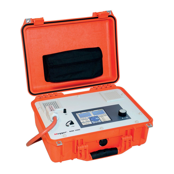
- Page 1 NIM 1000 Net Impedance Meter USER GUIDE Issue: 04 (06/2016) - EN Article number: 82941...
-
Page 3: Consultation With Megger
E: team.dach@megger.com Megger All rights reserved. No part of this handbook may be copied by photographic or other means unless Megger have before-hand declared their consent in writing. The content of this handbook is subject to change without notice. Megger cannot be made liable for technical or printing errors or shortcomings of this handbook. -
Page 4: Terms Of Warranty
During the period of warranty, Megger agree to repair faulty parts or replace them with new parts or parts as new (with the same usability and life as new parts) according to their choice. -
Page 5: Table Of Contents
Contents Contents Consultation with Megger ....................3 Terms of Warranty ......................4 Contents ........................... 5 Basic Notes ....................... 7 Technical Description ..................9 System Description .................... 9 Technical Data ....................11 Connections, Controls and Display ..............12 Electrical connection ..................13 Operation ...................... -
Page 7: Basic Notes
Working with products It is important to observe the general electrical regulations of the country in which the from Megger device will be installed and operated, as well as the current national accident prevention regulations and internal company directives (work, operating and safety regulations). - Page 8 Megger products in direct contact with water, aggressive substances and inflammatory gases and vapours is prohibited. The NIM 1000 is built to be robust and can withstand the stresses it can expect to be subjected to in demanding everyday use. Nevertheless, it is a precision measuring device which needs to be treated with the appropriate care.
-
Page 9: Technical Description
Fault detection in low voltage grids is another area of application of the device. For example, the NIM 1000 can be used to trigger a load-dependent fault which can then be located either with the help of a simultaneously connected measuring device or by means of multiple measurements at various connection points. - Page 10 Technical Description Features The NIM 1000 combines the following features in one device: • Compact and sturdy design for portable use in the field • Easy and convenient operation via rotary encoder • Single and three phase measurement • High test current of up to 1000 A •...
-
Page 11: Technical Data
Technical Description Technical Data The NIM 1000 is defined by the following technical parameters: Parameter Value Test current Range 80 A … 1000 A (adjustable) • Maximum current as a peak value ≤1000 A at 400 V • depends on the network ≤600 A at 230 V... -
Page 12: Connections, Controls And Display
Technical Description Connections, Controls and Display The NIM 1000 has the following connection, display and control elements: Element Description Display Rotary encoder USB port Connection cables Trigger output... -
Page 13: Electrical Connection
WARNING disconnected in reverse order: first disconnect the phase conductors, then the neutral conductor. Connection diagram The following figure shows the simplified connection diagram for the NIM 1000: The fused measurement cables are colour-coded (brown = black = L2, grey =... - Page 14 100 V and 480 V. • The NIM 1000 must be connected to the neutral conductor and at least one phase. If the neutral conductor is not accessible, the blue connection cable must be connected to a free phase conductor.
- Page 15 Electrical connection Connection to mains Using the included NIM 1000-A adapter, the NIM 1000 can be quickly and safely socket connected to a mains socket for the purposes of measurement or the export of measurement data. The plug is designed as a Schuko plug (CEE 7/4) but it can also be connected to sockets of different designs without problem using the appropriate accessories.
-
Page 16: Operation
As soon as one of the three connection cables has been connected to a low voltage Power on phase with sufficient supply voltage (100 V ... 480 V), the NIM 1000 automatically turns After the short switching on process, the system waits for confirmation from the user that the electrical connection has been finished. - Page 17 Operation If it has been possible to detect the rotary field’s direction of rotation, this will be indicated by the colour in which the phase designations are displayed: Counter-clockwise rotary field Clockwise rotary field If, however, it is not possible to determine the direction of rotation say, for example, because less than three phases have been connected or because one phase has accidentally been connected multiple times, the phases are displayed in a black font.
-
Page 18: System Settings
Operation System Settings Selecting the menu item takes you directly to the system menu, where the following functions and submenus are available: Menu Description item Submenu with detailed system information Information on the current versions of the various software components Hardware information (e.g. -
Page 19: Performing Measurements
Operation Performing Measurements Selecting the operating By selecting the menu item in the main menu you will reach a sub menu in which mode you may select your desired operating mode. In principle, measurements may be carried out either in normal network impedance measuring mode or in fault detection mode. Normal network impedance measuring takes place with a constant measuring current and over a freely-adjustable duration or number of measurements. -
Page 20: Network Impedance Measurement
If the NIM 1000 is connected to a mains socket (with fusing of up to 16 A), the 80 A setting which has been particularly dimensioned for this type of application should be selected! Total measurement duration (0 …... - Page 21 Operation Explanations When it comes to the load calculation, the NIM 1000 utilises the following physical concerning the load correlation between the measurements for short-circuit power P , the maximum rated calculation output P and the anticipated voltage dip V Z / P (1 –...
-
Page 22: Performing The Measurement
Operation 4.2.1.2 Performing the Measurement Start measurement Once all the settings have been carried out and checked, the measurement can be started with the menu item If this is the first measurement after switching on the device or if the calibration values were reset before the measurement (see previous page), calibration will be carried out right after the start in order to set the preset maximum measuring current. -
Page 23: Analysing Measurement Results
Operation 4.2.1.3 Analysing Measurement Results The red curve is hidden on completion of the measurement. Instead, dark-green Interpretation of the curves envelope curves are marked above and underneath the light-green medium value curve, these envelope curves represent the upper and lower limit of 99.7% of the measured values. - Page 24 Operation Impedance of the PEN In the case of measuring more than one conductor, there is another option named PEN conductor available for selection. When this option is selected, the calculated impedance of the PEN conductor and the following values for a three-phase short-circuit (calculated in accordance with IEC 60909-0) are displayed: Three-phase peak short-circuit current Three-phase sustained short-circuit current...
-
Page 25: Measuring In Fault Mode
In fault mode, the current is increased as linearly as possible over 8 measurements up to the set maximum value in this case. If the NIM 1000 is connected to a mains socket (with fusing of up to 16 A), the 80 A setting which has been particularly dimensioned for this type of application... -
Page 26: Performing The Measurement
Operation 4.2.2.2 Performing the Measurement Once all the settings have been carried out and checked, the measurement can be Starting the measurement started with the menu item Performing the In fault mode, the measurements take place in quick succession. Starting at a low value, measurement the measuring current is increased as linearly a possible by a certain amount with each measurement and, after 8 measurements, reaches the set maximum value. -
Page 27: Identifying And Locating Faults
Operation 4.2.2.3 Identifying and Locating Faults Comparing curves Following the measurement, the measured values and curves can be examined for any conspicuous jumps and thus the triggering or subsiding of the fault at a certain measuring current value can be detected. As is the case even during the measurement, different diagram types can be switched between using the menu item (see also the previous page). -
Page 28: Exporting The Measured Data
Once a measurement has been completed, the measured data recorded is written to the internal memory of the NIM 1000. Measurement data records already contained in the memory will not be overwritten in this process and, thanks to the non-volatile memory, the data will be maintained permanently too. -
Page 29: Maintenance And Care
Maintenance and care Maintenance and care Repair and maintenance work has to be carried out by Megger or authorised service Repair and maintenance partners using original spare parts only. Megger recommends having the system tested and maintained at a Megger service centre once a year. -
Page 30: Annex 1: Measuring Accuracy
Annex 1: Measuring Accuracy Annex 1: Measuring Accuracy... - Page 31 Annex 1: Measuring Accuracy Voltage Operating uncertainty Current and measuring range 115 V 3% ± 1 mΩ ≥ 200 A for |Z| > 10 mΩ 100 A for |Z| > 200 mΩ 80 A for |Z| > 500 mΩ 5% ± 1 mΩ 100 A for 40 mΩ...
-
Page 32: Annex 2: Measuring Range
Annex 2: Measuring Range Annex 2: Measuring Range Voltage Current range Measuring range 115 V 300 A |Z| < 40 mΩ 200 A |Z| < 300 mΩ 100 A |Z| < 1100 mΩ 80 A |Z| < 2500 mΩ 230 V 600 A |Z| <... - Page 33 Tento symbol indikuje, že výrobek nesoucí takovéto označení nelze likvidovat společně s běžným domovním odpadem. Jelikož se jedná o produkt obchodovaný mezi podnikatelskými subjekty (B2B), nelze jej likvidovat ani ve veřejných sběrných dvorech. Pokud se potřebujete tohoto výrobku zbavit, obraťte se na organizaci specializující se na likvidaci starých elektrických spotřebičů...
Need help?
Do you have a question about the NIM 1000 and is the answer not in the manual?
Questions and answers