Kübler CODIX 540 Operating Instructions Manual
Electronic totaliser
Hide thumbs
Also See for CODIX 540:
- Operating instructions manual (33 pages) ,
- Operating instructions manual (20 pages)
Advertisement
Operating instructions
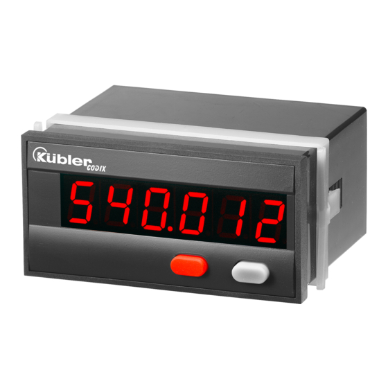
Electronic totaliser
CODIX 540
1. Preface
Please read this instruction manual
entirely and carefully before installa-
tion and start-up. Please observe all
warnings and advice, both for your
own safety and for general plant
safety. If the device is not used in
accordance with this instruction
manual, then the intended protec-
tion can be impaired.
2. Safety Instructions and Warnings
Please use the device only if its
technical condition is perfect. It
should be used only for its intended
purpose. Please bear in mind safety
aspects and potential dangers and
adhere to the operating instructions
at all times.
Defective or damaged devices
should be disconnected from the
mains immediately and taken out of
operation.
The device shall not be opened.
Use the repair service of the manu-
facturer.
Only connect the device to the elec-
tricity networks provided to that pur-
pose.
The safety of the system in which
the device is integrated is the
responsibility of the installer.
Disconnect all electricity networks
prior to any installation or mainte-
nance work.
Use exclusively cables approved in
your country and designed for your
temperature and power ranges.
Installation and service work shall
be carried out exclusively by quali-
fied personnel.
The device must compulsorily be
protected with approved external
fuses. The value of these fuses can
be found in the technical informa-
tion.
This symbol is used on the device to
!
remind of the existence of dangers,
which are referred to in this manual.
2.1 Use according to the intended purpose
The counter detects pulses up to max. 60 kHz
and offers a wide variety of different operating
modes. Use for any purpose over and beyond
this will be deemed as not in accordance with its
intended purpose and thus not complying with
the requirements.
The application area for this device lies in indus-
trial processes and controls, in the fields of man-
ufacturing lines for the metal, wood, plastics,
paper, glass, textile and other like industries.
Over-voltages at the terminals of the device
must be kept within the limits of Over-voltage
Category II.
The device must only be operated when mount-
ed in a panel in the correct way and in accor-
dance with the section "Technical Data".
The device is not suitable for use in hazardous
areas and for areas excluded in EN 61010 Part 1.
If the device is used to monitor machines or
processes in which, in the event of a failure of
the device or an error made by the operator,
there might be the risk of damaging the machine
or causing an accident to the operators, it is
your responsibility to take the appropriate safety
measures.
The device has been designed for indoor opera-
tion. It may nevertheless be used outdoors, provid-
ed the technical data is adhered to. In this case,
take care to provide suitable UV protection.
Advertisement
Table of Contents

Subscribe to Our Youtube Channel
Related Manuals for Kübler CODIX 540


Summary of Contents for Kübler CODIX 540
- Page 1 Operating instructions Electronic totaliser CODIX 540 1. Preface This symbol is used on the device to Please read this instruction manual remind of the existence of dangers, entirely and carefully before installa- which are referred to in this manual. tion and start-up. Please observe all warnings and advice, both for your 2.1 Use according to the intended purpose...
- Page 2 2.2 Mounting in a control panel The device must be protected exter- Mount the device away from heat nally for its proper operation. Informa- sources and avoid direct contact with tion about the prescribed fuses can corrosive liquids, hot steam or similar. be found in the technical information.
- Page 3 2.4 Cleaning and maintenance 3. Description The front side of the unit should only be cleaned 6-digit 14-segment LED display, 14 mm using a soft damp (water!) cloth. Cleaning of the Help Text display embedded rear side is not planned and is the Preset counter with two relay outputs responsibility of the service personnel or of the Preset entry via the front keys or via the Teach-In...
-
Page 4: Setting Of The Operating Parameters
4. Inputs 6. Programming routine The programmable parameters of the device are Dynamic count input. described below, in succession. The device is RESET fully programmed after one pass of the routine. Dynamic RESET input. Linked in parallel to the red RESET key. Sets the counter to zero. The first values stated correspond to the factory settings 5. - Page 5 6.5 End of programming Input resistance: appr. 5 kOhm Minimum pulse length for the reset input: 5 ms Switching level: The programming routine is Standard level (HTL): repeated once more. The AC power supply: Low: 0 ... 4 V DC values set until now can be High: 12 ...
-
Page 6: Terminal Assignment
8. Terminal assignment 9. Ordering code 6.540.012.XX0 Input sensitivity 0 = Standard level (HTL) A = 4 ... 30 V DC level Low (0 ... 2 V DC) High (4 ... 30 V DC) X2 terminal assignment Suply voltage Pin AC Version DC Version 0 = 100 ...
Need help?
Do you have a question about the CODIX 540 and is the answer not in the manual?
Questions and answers