Kübler CODIX 541 Operating Instructions Manual
Electronic display counter
Hide thumbs
Also See for CODIX 541:
- Operating instructions manual (32 pages) ,
- Operating instructions manual (62 pages) ,
- Operating instructions manual (54 pages)
Table of Contents
Advertisement
Quick Links
Operating instructions
Electronic display counter
CODIX 541, 542, 543 and 544
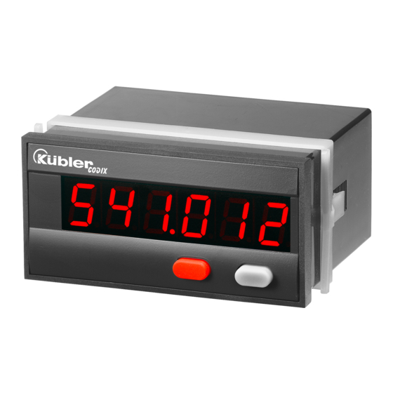
1. Description
CODIX 541
Please note: Read first chapter 1-4 of CODIX
544 and go on on page 4.
CODIX 542
Please note: Read first chapter 1-4 of CODIX
544 and go on on page 6.
CODIX 543
Please note: Read first chapter 1-4 of CODIX
544 and go on on page 7.
CODIX 544
CODIX 544 is a multipurpose device. Depend-
ing on the programmed basic function, the
device operates like
• the pulse counter CODIX 541 (see page 4) or
• the frequency meter CODIX 542 (see page 6) or
• the time meter CODIX 543 (see page 7)
t
1.1. Preface
Please read this instruction man-
ual entirely and carefully before
installation and start-up. Please
observe all warnings and advice,
both for your own safety and for
general plant safety. If the device
is not used in accordance with
this instruction manual, then
the intended protection can be
impaired.
2. Safety Instructions and Warnings
t
Please use the device only if its
technical condition is perfect. It
should be used only for its intend-
ed purpose. Please bear in mind
safety aspects and potential dan-
gers and adhere to the operating
instructions at all times.
Defective or damaged devices
should be disconnected from the
mains immediately and taken out
of operation.
The device shall not be opened.
Use the repair service of the
manufacturer.
www.kuebler.com
Only connect the device to the
electricity networks provided to
that purpose.
The safety of the system in which
the device is integrated is the
responsibility of the installer.
Disconnect all electricity networks
prior to any installation or mainte-
nance work.
Use exclusively cables approved
in your country and designed
for your temperature and power
ranges.
Installation and service work shall
be carried out exclusively by
qualified personnel.
The device must compulsorily be
protected with approved external
fuses. The value of these fuses
can be found in the technical
information.
This symbol is used on the de-
!
vice to remind of the existence of
dangers, which are referred to in
this manual.
2.1 Use according to the intended purpose
The counter detects and measures pulses,
times and frequencies up to max. 60 kHz and
offers a wide variety of different operating
modes. Use for any purpose over and beyond
this will be deemed as not in accordance with
its intended purpose and thus not complying
with the requirements.
The application area for this device lies in
industrial processes and controls, in the fields
of manufacturing lines for the metal, wood,
plastics, paper, glass, textile and other like
industries. Over-voltages at the terminals of
the device must be kept within the limits of
over-voltage Category II.
The device must only be operated when
mounted in a panel in the correct way and in
accordance with the section "Technical Data".
Page 1
Advertisement
Table of Contents

Related Manuals for Kübler CODIX 541


Summary of Contents for Kübler CODIX 541
- Page 1 • the pulse counter CODIX 541 (see page 4) or The device must compulsorily be • the frequency meter CODIX 542 (see page 6) or protected with approved external •...
-
Page 2: Mounting Instructions
The device is not suitable for use in hazardous 2.3 Electrical Installation areas and for areas excluded in EN 61010 Part The device must be disconnected 1. If the device is used to monitor machines or from any power supply prior to any processes in which, in the event of a failure of installation or maintenance work. - Page 3 • The device has been designed for overvolt- 2.5 Start-up age category II. If higher transient voltages The following points must be checked before cannot be excluded, additional protection starting up the device: measures must be taken in order to limit the 1.
- Page 4 The display shows Operating mode pulse count- er. Continued in point 4. of CODIX 541 on page 4. c. After releasing the keys, the display shows Operating mode frequency c1. Hold the left key pressed and press the right meter.
- Page 5 4.3 Input mode 2. Inputs INP A Dynamic count input. Count input and count direc- INP B tion input Dynamic count input. INP A: Count input SET/RESET INP B: Count direction input Dynamic SET/RESET input. Linked in parallel to the red SET/RESET key. Resets the counter to the predefined setting value.
- Page 6 4.5 Dividing factor 4.9 End of programming The programming routine is It can be set from 00.0001 up repeated once more. The to 99.9999. values set until now can be The decimal point is set to checked and modified. 4 decimal places. „0“ is not accepted! The programming routine 4.6 Decimal point...
- Page 7 4.1 Polarity of the inputs 4.7 Max. time to wait until „0“ is displayed This parameter indicates, how long it takes, when measuring is active, until „0“ is displayed. npn: switching for 0 V pnp: switching for +U Max. time to wait 00.1 s (min.
- Page 8 4.3 Input mode 2. Inputs INP A Start input (depending on the input mode Start/Stop via Inp B. counting chosen) while Inp B (Gate) not active INP B or open Start/Stop or gate input (depending on the input mode chosen) Start/Stop via Inp B.
-
Page 9: Technical Data
The device will be set to the Input resistance: appr. 5 kOhm set point by pressing the red SET/RESET key or activating Count frequency CODIX 541: the SET/RESET input. 100…240 VAC ±10% AC power supply: SET value 0…999 999 or Input level: Standard 4…30 V DC... - Page 10 Count frequency CODIX 542: Optocoupler output (optional): Frequency measurement NPN optocoupler with open collector and open Accuracy <0.1 % emitter; max. switching performance: Measuring principle: 30 V DC/15 mA < 38 Hz: period measurement > 38 Hz: gating time measurement Sensor supply voltage: gating time 26.3 ms (Voltage output for external sensors)
-
Page 11: Terminal Assignment
appr. 150 g Weight: 7. Delivery includes: Digital display IP65 (front, device only) Protection: 2 pin screw terminal RM 5.08 7 pin screw terminal RM 3.81 Panel mounting clip 6. Terminal assignment Seal Multilingual operating instructions 8. Ordering code: 6.541.01X.XX0 6.542.01X.XX0 6.543.01X.XX0 6.544.01X.XX0...
Need help?
Do you have a question about the CODIX 541 and is the answer not in the manual?
Questions and answers