
Related Manuals for Kübler CODIX 924


Summary of Contents for Kübler CODIX 924
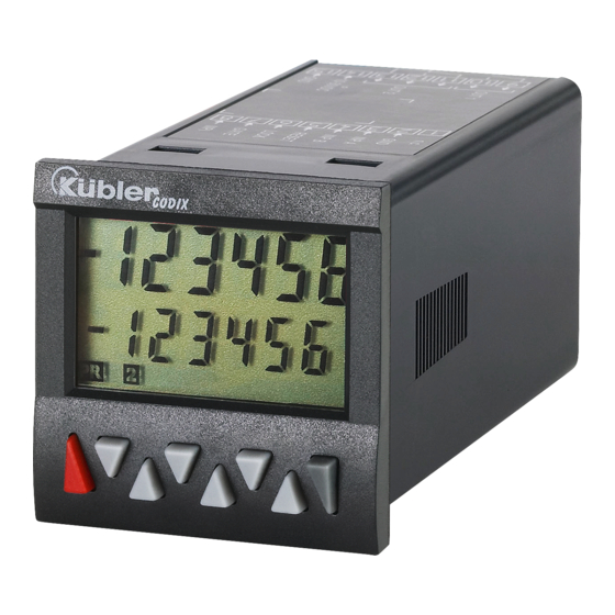
- Page 1 Electronic Preset CODIX 924 Counter With two presets Models LCD positive LCD positive, green backlighting LCD negative, red backlighting LCD negative, red-green backlighting...
-
Page 2: Table Of Contents
Table of Contents Preface Safety instructions and Warnings Use according to the intended purpose Mounting in a control panel Electrical Installation Cleaning and maintenance Description Display/Operating elements Inputs INP A, INP B RESET GATE LOCK INPUT Outputs Output 1 Output 2 Active Outputs Programming Entering the programming... - Page 3 10.8 Sensor supply voltage 10.9 Climatic Conditions 10.10EMC 10.11Device safety 10.12Mechanical Data 10.13Connections 11 Scope of Delivery 12 Ordering codes 13 Frequencies (typical) 13.1 Pulse counter 13.2 Frequency meter 14 Input modes: Pulse counting 15 Input modes: Timing 16 Input modes: Frequency meter 17 Output operations 18 Dimensional Drawings www.kuebler.com...
-
Page 4: Preface
The application area for this device lies in industrial Preface processes and controls, in the fields of manufacturing lines for the metal, wood, plastics, Please read this instruction manual paper, glass, textile and other like industries. Over- entirely and carefully before installation voltages at the terminals of the device must be kept and start-up. -
Page 5: Electrical Installation
unused screw terminals must be screwed to the Electrical Installation stop, so that they cannot loosen and get lost. The device must be disconnected The device has been designed for overvoltage • from any power supply prior to any category II. If higher transient voltages cannot installation or maintenance work. -
Page 6: Description
Description T1-6 Decade key T1 … T6 6-digit multifunction LCD display P Prog/Mode key Easy-to-read 2-line LCD-display with annunciators R Reset key for both the displayed preset and the status of the two outputs Current count value / main counter Simultaneous display of the actual value and of the Preset value/ Total count/ Batch counter presets or auxiliary counters... -
Page 7: Outputs
Outputs Entering a Submenu The Submenu is opened with the Output 1 Prog/Mode key and the first menu item is displayed. Relay with potential-free make (NO) contact or optocoupler with open emitter and collector Selecting the menu items Output 2 The Prog/Mode key is used to Relay with potential-free make (NO) contact or select a menu item within the... -
Page 8: Programming Menu
Pressing the Prog/Mode key 7.8.2 Table: Parameter Sets acknowledges this prompt and P.SEt 1 P.SEt 2 P.SET 3 terminates the programming; the modified settings are saved in Func Count Count Count the EEPROM. InP.PoL The text SAVE is FiLtEr displayed for 2 s Count Cnt.dir uP.dn... -
Page 9: Pulse Counter
Quadrature x4 7.8.4 Pulse Counter INP A: count input 0° INP B: count input 90° 7.8.4.1 Mainmenu for the Signal and Each pulse edge of INP A and Control inputs INP B will be counted. Mainmenu for programming the Ratio measurement [A / B] signal and control inputs Inp A: count input A Inp B: count input B... - Page 10 Count mode SUBTRACT Count mode ADDING with Output 1 active when automatic reset and Total count status < preset value 1 counter Output 2 active when Output 2 (timed signal) active count status < 0 when main counter = preset Reset to preset 2 value 2 Automatic reset to zero when...
-
Page 11: Tacho/Frequency Meter
7.8.4.3 Mainmenu for configuration Manual reset (with red key) and electrical reset (reset input) Mainmenu for matching the input pulses and display No reset possible (red key and reset input inhibited) Multiplication factor Only electrical reset possible Multiplication factor can be (reset input) programmed from 00.0001 to 99.9999. - Page 12 Input mode Frequency Measurement 7.8.5.2 Mainmenu for configuration Mainmenu for matching the input Simple frequency pulses and display measurement Inp A: Frequency input Inp B: no function Multiplication factor Differential measurement Multiplication factor can be programmed from 00.0001 to [A – B] 99.9999.
-
Page 13: Timer
Display colour (for device 6.92x.x1x3.xx0) Timing can only be controlled via the Gate input Display colour Upper line Inp A and Inp B: no function Lower line The timer is reset by means of a Display colour RESET (to zero when adding, to Upper line preset 2 when subtracting) and Lower line... - Page 14 Lock input main counter = preset value 2 Batch counter counts the number When the Lock input is activated of automatic repetitions of preset the programming is inhibited. Output 1 active when batch counter > preset 1 manual reset sets both counters When the Lock input is activated to zero the setting of the preset values is...
- Page 15 Tracking preset mode Display colour (for 6.92x.x1x3.xx0] Display colour When preset 2 is changed then upper line preset 1 automatically tracks it. lower line Reset to zero Preset 1 relative to preset 2 (see Display colour also section 17. Output upper line operations) lower line...
- Page 16 SUB mode output operations: 7.8.6.6 Mainmenu for Preset 2 permanent signal at Output 1, Mainmenu for Preset 2 becomes passive when count < Preset 1 ADD mode output operations: timed signal at Output 1, ADD mode output operations: becomes active when count > permanent signal at Output 2, Preset 1.
-
Page 17: Setting The Presets
Preset 2 and subsequently with 7.9.2 Setting with Teach-In Function negative direction and when Program the MPI input to tEAch count < Preset 2 SUB mode output operations: timed signal at Output 2, becomes passive with negative In programming mode, select the direction and when count <... -
Page 18: Connections
9.2.2 Version with Optocouplers Connections N° Designation Function Collector 1 Output 1 10 Emitter 11 Emitter 2 12 Not connected Output 2 13 Collector 2 14 AC: 100 … 240 VAC ± 10% N~ Supply DC: 10..30 VDC voltage 15 AC: 100 … 240 VAC ± 10% L~ Supply DC: GND (0 VDC) voltage... -
Page 19: Timer
Response time of the outputs: Output 2 1-channel operation < 100 ms @ 40 kHz Relay with changeover contact < 350 ms @ 65 kHz Prescribed fuse: 2-channel operation < 150 ms @ 40 kHz Switching voltage max. 250 VAC/ 150 VDC <... -
Page 20: Device Safety
10.11 Device safety 12 Ordering codes Design to: EN 61010 Part 1 6.924.X1XX.XX0 Protection Class: Protection Class 2 (front side) Input trigger levels 0 = Standard (HTL) Only the front side is classified as accessible A = 4-30 VDC* for the operator. Supply voltage Application area: Pollution level 2... -
Page 21: Frequency Meter
4-30 V level typ. Low 1,0 V typ. High 4,0 V AddAr AddTot SubAr SubTot Trail AddBat SubBat TrailAr 9 kHz 2,7 kHz 2,4 kHz Cnt.Dir Up.Dn 9 kHz 2,7 kHz 2,4 kHz Up.Up Quad 9 kHz 1,2 kHz 1,2 kHz Quad 2 9 kHz 1,2 kHz... -
Page 22: Input Modes: Pulse Counting
14 Input modes: Pulse counting Function Diagram PNP: Count on rising edge NPN: Count on falling edge Note: No counting when GATE input is active P = Preset Cnt.Dir Inp A: Count input Inp B: Count direction Add: Display 0 --> Preset Sub: Display Preset ->... - Page 23 Function Diagram PNP: Count on rising edge NPN: Count on falling edge Note: No counting when GATE input is active Quad 4 A 90° B Inp A: Count input Count on rising and on falling edges Inp B: Count input Count on rising and on falling edges, Reverse direction...
-
Page 24: Input Modes: Timing
15 Input modes: Timing Function Diagram PNP: Count on rising edge NPN: Count on falling edge InA.InB Inp A: Start Inp B: Stop Add: Display 0 --> Preset Sub: Display Preset -> 0 InB.InB Inp A: no function Inp B: Start/Stop Add: Display 0 -->... -
Page 25: Input Modes: Frequency Meter
16 Input modes: Frequency meter Function Diagram PNP: Count on rising edge NPN: Count on falling edge Inp A: Frequency input Inp B: no function AsubB Inp A: Frequency input 1 Inp B: Frequency input 2 Formula: A - B AaddB Inp A: Frequency input 1 Inp B: Frequency input 2... -
Page 26: Output Operations
17 Output operations Mode Diagram Mode Diagram Only in the mode Additionally in the mode AddAr SubAr AddBat SubBat AddTot SubTot www.kuebler.com Page 26... - Page 27 Mode Diagram Trail TrailAr www.kuebler.com Page 27...
-
Page 28: Dimensional Drawings
18 Dimensional Drawings Dimensions in mm [inch] Panel cut-out www.kuebler.com Page 28...
Need help?
Do you have a question about the CODIX 924 and is the answer not in the manual?
Questions and answers