Table of Contents
Advertisement
Quick Links
Advertisement
Table of Contents

Related Manuals for Fisher Research Labs M-Scope Series


Summary of Contents for Fisher Research Labs M-Scope Series
- Page 1 S E C U R I T Y S O L U T I O N S ® REVISION LEVEL 3.0...
-
Page 2: Table Of Contents
OPERATION MANUAL Fisher Labs M-Scope ® Portable Walk-Through Metal Detector U.S. and E.U. Patents Pending Copyright© 2011 First Texas Products L.L.C. All Rights Reserved. TABLE OF CONTENTS Features ......pg. 3 Introduction ......pg. 4 M-Scope Expanded View ..pg. 4 Assembly ...... -
Page 3: Features
FEATURES • Modular construction for rapid deployment • 40 Hours of battery life on a single charge • Intuitive three-zone detection and alarm status indicators, on both entry and exit sides • Audio alert with adjustable volume control • Intuitive, user-friendly control panel •... -
Page 4: Introduction
COnTROL PanEL INTRODUCTION Fisher Labs is excited to introduce the M-Scope Portable Walk- ® Through Metal Detector! The M- Scope , the world’s most versatile ® walk-through metal detector, brings Fisher’s expertise, innovation and reputation for quality metal detection solutions to the critical and demanding security market. BaSES... -
Page 5: Assembly
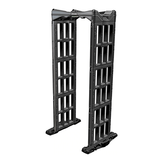
M-SCOPE PORTABLE WALK-THROUGH METAL DETECTOR ® ASSEMBLY INSTRUCTIONS Begin by selecting the most even and level surface on which to assemble your M-Scope unit. Remove the transport straps and step un-stack all the components. FIG. A Place the two INTERCHANGEABLE base units on the selected ground as shown in FIG. B. Fig. - Page 6 The side walls might tipp over when they are not connected to each other with the Control Panel, so before assembling the walls, make sure that the bases will be stable enough to build on. (Once the unit is fully assembled, the walls and Control step Panel will form a stable structure).
- Page 7 There are two types of panels in the M-Scope system. They are called ‘Transmitter’ and ‘Receiver’ panels. Here are several ways in which you can easily tell them apart. FIG. G step Receiver panels have 32 spring loaded contact pins Transmitter panels have 16 spring loaded contact pins b.
- Page 8 Place a Transmitter Panel on one base and a Receiver Panel on the other base. Fasten the latches to secure the side panels to step the bases. FIG. H Fig. H base draw latches Then stack the two remaining Receiver Panels on the receiver side (Panels with LEDs). Repeat on the other side. Fasten Panels step with latches.
- Page 9 Place the Control Panel on top with the wheels over the receiver side (with white labels and LEDs). Latch the Control Panel step to the side panels. If the latches will not engage, then the Control Panel is installed backwards: The Control Panel will fit onto the side panel even if incorrectly oriented 180°...
-
Page 10: Disassembly
DISASSEMBLY INSTRUCTIONS The M-Scope should be powered down (turned off) prior to disassembling the unit, or prior to disconnecting or swapping any of the transmitter and receiver panels. Re-extend the outriggers as in step 4. Undo the control unit’s latches and step remove the control unit. - Page 11 Turn the bases upside down and place them on the control unit. FIG. S step Fig. s All of the components have a series of projections and indentations that are designed to nest within each other when the components are stacked together for transport. These are called the ‘Stacking Features’ . They keep the components from step sliding around within the stack when they are strapped together for storage or transport.
-
Page 12: Strap Installation
STRAP INSTALLATION INSTRUCTIONS Transport Strap with Protective Foam Cups Your MScope portable metal detector is equipped with a new Transport Strap. This strap has protective foam cups that will absorb impact occurring while shifting the collapsed device to stand up on end. Follow the normal Disassembly Instructions of your operation manual on page 9, assuring the protection foam cups fit over the top 3 panels when stacked (see photos below). -
Page 14: Getting Started
GETTING STARTED COntROL paneL KeYpaD (bottom view) All of the M-Scope’s commands are entered through the twelve-button keypad on the control unit. The two up/down arrows are essentially single function buttons. The other ten buttons labeled 0 through 9 are all multi-function buttons. Multi- function buttons are annotated with corresponding abbreviations. -
Page 15: Basic Start Up Operation
BASIC START UP OPERATION Turn the unit on by momentarily pushing the on/off RESEARCH LABS step [numeral 0] button on the control panel keypad. The unit will power up and begin a self diagnostic check. Battery 13.3 The LCD will display the Title Screen and the battery voltage during the self-check. -
Page 16: Detection And Alarms
DETECTION AND ALARMS Sensing Subjects in the M-Scope The metal detection alarm decision-making process begins the moment a subject breaks any one of the six invisible beams of infrared light inside the M-Scope’s passageway; typically one of the three beams at the portal’s entrance. Note that the LED bar graph continuously displays the received signal’s strength, but the alarm will not be triggered until something enters the security gate and passes through one of the sensors’... - Page 17 Zone Indication The M-Scope has three zones. If one or more of the zones detect target signals strong enough to exceed the alarm threshold, the audio alert will sound, and the LED bar graph will flash several times. The zone indicator light corresponding to the zone where the strongest signal was received will glow red.
-
Page 18: Advanced Functions
ADvANCED FUNCTIONS Volume Volume You may exit any of these menu modes by pressing the exit key [numeral 0], or by waiting for the ten second keyboard timeout, after which the M-Scope will Volume = “ 0 = Exit = “ + ” automatically revert to normal operating mode. - Page 19 2. SENSITIvITY MENU Sensitivity The sensitivity setting determines the unit’s ability to detect metal objects. The higher the sensitivity, the more responsive it will be to relatively small metal concentrations. To adjust the sensitivity, press the sensitivity key (numeral 2). Use the up/down arrows to adjust the sensitivity setting to any number from 1 to 99.
- Page 20 5. RATE ALARM MENU To access the rate alarm menu, press the rate key [numeral 5] while the M-Scope is in normal operating mode. The LCD will show the rate alarm setting. There are Rate Alarm six possible speed settings including the disable rate alarm setting [i.e. 0.2m/S, 0.5m/S, 1.0m/S, 1.5m/S, 2.0m/S, Disabled].
- Page 21 Access Menus / Password Protection (Continued) Editing the access menu is the way to change access codes, and enable or disable the access Code Lock Code Lock protection feature. 1 = Master 1 To change an access code, open the Edit Disabled 2 = User 2 access menu, and then press the numeral key...
- Page 22 PRESETS The M-Scope’s ideal group of settings may change with different users’ individual preferences, or in different security applications. The M-Scope can store three separate groups of settings under the headings of User Presets 1, 2 and 3. These correspond to numeral keys 7,8 and 9 respectively.
-
Page 23: Diagnostic Screens
Please contact the Fisher factory or your Fisher Sales Representative, or Distributor if you have not had technical training on accessing the diagnostic screens! Diagnostics Screens The M-Scope has a Diagnostic Mode that can be used to check the performance of its six Photo Detector channels, and of its three separate metal detector zones. -
Page 24: Led Testing
LED Testing The LEDs can be controlled manually while in the diagnostics mode by pressing the different numeral keys. Duration is approximately 4.5 seconds, then returning to diagnostic mode. The ready light will go green and the LED bar graph displays the signal strength. Bar graph LED 1 on All Zone [“RX”... -
Page 25: Tips
TIPS & TROUBLESHOOTING M-Scope batteries typically need to be changed after two or three years. Weak batteries may lead to several problems and error messages including blocked photo diodes. Many error messages can be corrected by recharging both batteries to a full charge. - Page 26 Tips & Troubleshooting (Continued) 11. Remember that when storing or transporting your M-Scope, make sure that you secure the latches in their locked position to prevent them from bending or breaking. CORRECT INCORRECT latches in the locked position latches unlocked 12.
-
Page 27: Specifications
To return your detector for service, please first contact Fisher Labs for a Return Authorization (RA) Number. Reference the RA number on your package and return the detector within 15 days of calling to: Fisher Research Labs, Inc. 1465 Henry Brennan Dr. El Paso, TX 79936 U.S.A. -
Page 28: Accessories
ACCESSORIES AND PARTS 1465-H Henry Brennan, El Paso, Texas 79936 Tel 915.225.0333 • Fax 915.225.0336 • 1-800-685-5050 www.fisherlab.com email: info@fisherlab.com MMSCOPE Copyright©2014 Fisher Research Labs 012914...
Need help?
Do you have a question about the M-Scope Series and is the answer not in the manual?
Questions and answers