Table of Contents
Advertisement
Quick Links
Advertisement
Table of Contents

Related Manuals for Fisher Research Labs iMpulse AQ Limited


Summary of Contents for Fisher Research Labs iMpulse AQ Limited
- Page 2 Detector. The Impulse AQ® Limited is the first detector to emerge from the collaboration of Fisher Research Labs and Alexandre Tartar. The Impulse AQ® Limited is designed to be an instant classic, designed for the demanding beach-hunting enthusiast. Alexandre’s passion for scientific thought, physics and mechanical design bring us this breakthrough in pulse induction design.
- Page 3 In the meantime, Happy Hunting! -Fisher Research Labs THIS DETECTOR IS FACTORY SEALED Repair or Service to be conducted only by Fisher Research Labs®. Any attempt to modify, repair or open the sealed enclosure will void the manufacturer’s warranty.
-
Page 4: Table Of Contents
TABLE OF CONTENTS CONTENTS OF BOX ..................5 BATTERY ......................6 INITIAL ASSEMBLY ..................7 ASSEMBLY ..................... 8 QUICK START ....................13 USER CONTROLS ..................15 SEARCH TIPS ....................23 DETECTOR CARE ..................26 TROUBLESHOOTING.................. 30 10 COMPLIANCE ....................31 11 CODE OF ETHICS .................. -
Page 5: Contents Of Box
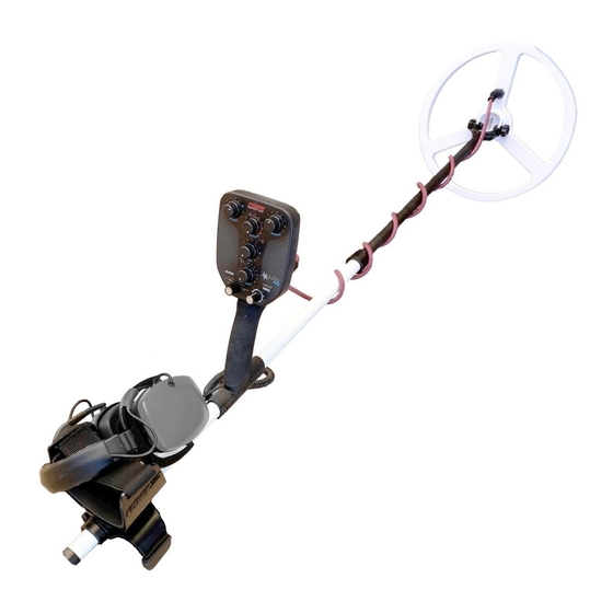
1 CONTENTS OF BOX The following preassembled components are in the box: Figure 1 Detector Components A. Upper Assembly Lower Assembly with 12” Searchcoil C. Headphones D. Owner’s Manual Components Box: E1 Power Cable E2 Charger E3 Iron Reference Target... -
Page 6: Battery
2 BATTERY This detector is powered by a battery pack. Additional battery packs are available for purchase. Charging the Battery NOTE: This battery is shipped at less than 100% charge. We recommend charging the battery before first operation. Power the unit off before charging. The Battery Pack can be charged while attached to the detector or when removed from the detector. -
Page 7: Initial Assembly
3 INITIAL ASSEMBLY Power Cable Upper Assembly (A) Locking Collar Lower Assembly (B) Figure 3 CAUTION: While adjusting the stem or searchcoil, be careful to avoid damaging the Power Cable and battery-pack connector. 1. Do not rest the rear of Upper Assembly (A) on any hard surfaces. 2. -
Page 8: Assembly
4 ASSEMBLY Connect Upper Assembly to Lower Assembly Internal Silver Button Cam Lock Locking Collar Lower Stem Upper Stem Lower Stem Upper Stem Lower Stem Figure 5 1. Position Lower Assembly (B) upright. 2. Rotate the Locking Collar fully in the counterclockwise direction. 3. - Page 9 ASSEMBLY (Continued) Connecting Searchcoil to Housing 1. Orient the Connector in your hand with the Wide Notch pointed upward (figure 5). 2. Push in connector to seat. If it doesn’t seat, rotate slightly left and right until it seats. 3. Turn the Locking Ring clockwise until it locks (figure 6). Figure 6 Wide notch pointed up...
- Page 10 ASSEMBLY (Continued) Connect Power Cable and Headphones Connect Power Cable to Tube 1. Go into well-lit area. 2. Push lower assembly to shortest detector length possible. 3. Stand detector up with control housing against the wall (figure 8). Figure 8...
- Page 11 ASSEMBLY (Continued) Figure 9 5. Pick up the female end of the Power Cable and align it with the connector protruding from the tube (figure 9). 6. Push Power Cable down onto connector and feel it seat. Rotate this piece Figure 10 7.
- Page 12 ASSEMBLY (Continued) Connect Power Cable to Battery Pack Align pins. Push Power Cable down onto connector and feel it seat. Handle with care: There is very little tactile feedback when connecting these parts. Hold the Power Cable upright with one hand, with other hand turn outer knurled ring clockwise to thread on the...
-
Page 13: Quick Start
5 QUICK START Basic Operation on Dry/Wet Sand et the Impulse controls to their preset positions, indicated on the faceplate with a blue circle: All Metal mode • Volume = 7 • Sensitivity = 4 • ATS = 8 • Iron Reject = NO EFFECT IN ALL METAL MODE •... - Page 14 QUICK START (Continued) Noise from Electromagnetic Interference (EMI) If the detector is experiencing EMI noise as evidenced by an uneven threshold tone in the All Metal mode, turn the Mode control to the Batt/Freq position and then rotate the Pulse/Freq control to find the quietest setting. Return the Mode control to the desired operating mode and then return the Delay control to the desired delay setting.
-
Page 15: User Controls
6 USER CONTROLS Figure 12 MODE Control The Mode selection switch has 6 positions: • Batt/Freq – Used for battery check and frequency adjustment to minimize • electrical interference. This position is not used for searching. All Metal – All targets induce a high tone. •... - Page 16 USER CONTROLS (Continued) The Battery Check position is used to evaluate the battery level as follows (the LED is located between Sensitivity and ATS potentiometers): Green LED: More than 30 minutes remaining Orange LED: 30 minutes or less remaining Red LED: Less than 15 minutes remaining NOTE: In any search mode, the detector signals a critically low battery by flashing the LED red and emitting a continuous tone.
- Page 17 USER CONTROLS (Continued) NOTE: The Frequency value will be programmed in after the Mode switch is moved from the Frequency position. After adjusting the Frequency and returning to a detection mode, you must re-set the Pulse Delay. In the Batt/Freq position the detector operates by default in Tone mode, but it is not recommended to use this position during actual target searching.
- Page 18 USER CONTROLS (Continued) • A high tone indicates a non-ferrous low-conductive target such as gold, platinum, lead, aluminum, or stainless steel. In addition to tonal variations, other audio anomalies (such as a nail causing a double-beep) will assist in identifying targets. The exact responses in Tone mode can be altered by the Reject control to increase or decrease the rejection of iron, and by the ATS control to alter the audio anomalies produced by some targets.
- Page 19 USER CONTROLS (Continued) Pulse Delay Control The Impulse AQ Limited transmits a pulse and then, after a time delay, samples the received signal. The Pulse Delay control can adjust this time delay from 7 µs to 11.5 µs. The lowest delay setting produces the greatest sensitivity to all targets, especially small gold pieces.
- Page 20 USER CONTROLS (Continued) Sensitivity Control The Sensitivity control increases or decreases the amplification of the receive signal. Normally, this determines how deep the detector will “see” a target. However, increasing the Sensitivity not only increases the amplification of target signals, but also of ground signals and EMI.
- Page 21 Reject should be used only when there is an abundance of iron. Reject is best adjusted using an example target you want to reject. A sample iron nail is included with the Impulse AQ Limited. 1. Choose Tone, Mute or Volcanic Sand mode.
- Page 22 USER CONTROLS (Continued) NOTE: The Reject feature of the detector does not function in the same way as the discrimination control on a VLF detector. It provides variable audio masking of iron targets as well as high-conductivity targets. Also, unlike some PI detectors, there is no target hole.
-
Page 23: Search Tips
7 SEARCH TIPS Search Environments Dry Beach On a dry beach, salt is not as much of an issue so the sample delay can be minimized, usually to 7 µs. While beaches often have a fair amount of trash, a beach scoop makes recovery fast and easy so All Metal mode is recommended. - Page 24 SEARCH TIPS (Continued) Pinpointing The Impulse AQ Limited does not have a “no-motion” pinpoint mode; the coil must be in motion in order to detect a target. When you initially detect a target, slow down and use short sweeps across the target, looking “through” the coil and taking a mental snapshot of the ground location where the peak target response occurs.
- Page 25 (heavy rings, thick chains) usually has a higher conductivity. But jewelry occupies a continuum of conductivities. Unlike many other PI detectors, the Impulse AQ Limited can detect most gold targets within the category of low conductors.
-
Page 26: Detector Care
Never stand the detector upside-down with the weight of the detector on the battery cable. When transporting the Impulse AQ Limited, either dismantle and place in a padded detector bag or lay in a horizontal position. Avoid placing other items on top of the detector. - Page 27 DETECTOR CARE (Continued) Coil Knob Assembly Disassemble in well-lit environment. Coil-Knob-Assembly Parts: 1. crew 2. . oil-Retaining-Nut 3. . x Insert Figure 13 Figure 14 Figure 15 Assemble the Pieces Together: The Screw fits into the Coil-Retaining-Nut to form a Coil-Knob-Assembly. Figure 16 After the fork is aligned over the coil ears, the Hex Insert is...
- Page 28 DETECTOR CARE (Continued) Coil Strain Relief Figure 19 The Coil Strain Relief is located at the front of the coil, in front of the lower stem fork. It is positioned here to prevent interference with the lower tube when the detector is laid in the resting position.
- Page 29 DETECTOR CARE (Continued) Securing Battery The Battery Pack can be charged while installed on the detector, or it can be removed and charged. Loosen or tighten the two knobs to detach or install. The Battery Pack slides through two ring-guides and reaches a stop on the rear ring-guide.
-
Page 30: Troubleshooting
9 TROUBLESHOOTING PROBLEM SOURCE SOLUTION The Detector emits Underwater/Wet Sand 1. Reduce swing speed. signals at the end of 2. If the problem persists, your sweeps. change the swinging direction. 3. If the problem persists, increase the pulse delay between 10 µs and 11.5 µs. -
Page 31: Compliance
10 COMPLIANCE FCC Class A Notice THIS DEVICE COMPLIES WITH PART 15 OF FCC REGULATIONS. OPERATION IS SUBJECT TO THE FOLLOWING TWO CONDITIONS: (1) THIS DEVICE MAY NOT CAUSE HARMFUL INTERFERENCE, AND (2) THIS DEVICE MUST ACCEPT ANY INTERFERENCE RECEIVED, INCLUDING INTERFERENCE THAT MAY CAUSE UNDESIRED OPERATION. -
Page 32: Code Of Ethics
11 CODE OF ETHICS • Always check Federal, State, County and local laws before searching. • Respect private property and do not enter private property without the owner’s permission. • Take care to refill all holes and leave no damage. •... -
Page 33: 12 2-Year Limited Warranty
Liability under this warranty is limited to replacing or repairing, at our option, the metal detector returned, shipping cost prepaid, to Fisher Research Labs. Shipping cost to Fisher Research Labs is the responsibility of the customer. To return your detector for service, please first contact Fisher Research Labs for a Return Authorization (RA) Number. -
Page 34: Accessories
13 ACCESSORIES The Impulse AQ® Limited requires a custom battery pack. If you should require additional battery packs, contact Fisher Research Labs. Fisher® Padded Carry Bag Rugged double stitched construction. Includes handy Exterior pocket for extra batteries or small Accessories. - Page 36 MIMPULSE-AQ 072220...
Need help?
Do you have a question about the iMpulse AQ Limited and is the answer not in the manual?
Questions and answers