Advertisement
Quick Links
*941367-00*
941367-00
Motorized Electric Latch Retraction
These instructions are for MEL conversion kits or MEL
devices with preinstalled motors.
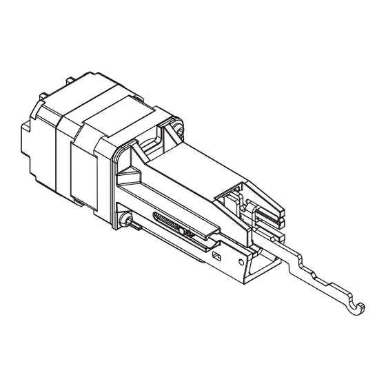
MEL motor
assembly
MEL
cover plate
Allegion Connect accessories available to order
106198
MEL-CON adapter cable with 8-pin connector
040069
MEL motor cable + MEL-CON adapter cable with 8-pin
connector
MEL 24/25 Series
Parts
Do not discard
Motor cable
only
(114320)
MEL 6' cable with motor cable
(47269206)
MEL motor mounting
4-20 x ¹⁄₄" FHP screws (qty 2)
If MEL is preinstalled in the device:
A.
Follow original device instruction up to the point
where this end mounting bracket step has been
completed.
Mark and Prepare 2 Holes
a
c
B.
Complete MEL wiring per steps 15-21 of this
instruction.
C.
Return to original device instruction at point you left
off, and complete installation.
If installing the MEL conversion kit, follow
the instruction steps as written.
1
Remove end cap
Installation Instructions
b
Metal/Metal/Métal
#25
#10-24
Wood/Madera/Bois
¹⁄₈" (3 mm) x 1" (25 mm)
Advertisement

Subscribe to Our Youtube Channel
Related Manuals for Falcon MEL 24 Series

Summary of Contents for Falcon MEL 24 Series
- Page 1 *941367-00* MEL 24/25 Series 941367-00 Motorized Electric Latch Retraction Installation Instructions If MEL is preinstalled in the device: These instructions are for MEL conversion kits or MEL devices with preinstalled motors. Follow original device instruction up to the point where this end mounting bracket step has been completed.
- Page 2 With device laying on a table or bench, remove the 2 Remove device end mounting bracket from door screws that connect mechanism case to center case Use long shank screwdriver. Slide back, remove and discard old cover plate Unhook baseplate from center case a.
- Page 3 Slide baseplate out of mechanism case Remove any existing dogging assembly baseplate f. Slide m...
- Page 4 Secure motor assembly a. Turn baseplate assembly upside down so pushpad is d. Set motor on flat surface. resting on a flat surface and motor mounting location is on the left. motor mounting location pushpad b. Place motor in left hand with LED status sticker facing e.
- Page 5 Slide mechanism case onto baseplate Reattach mechanism case to center case Insert pushbar guide ahead of motor assembly and hold in place (a) while sliding mechanism case onto baseplate (b) Use long shank screwdriver. Reattach device to door Reconnect center case to baseplate via hooking parts Insert remaining pushbar guide (nearest the center case) and slide mechanism case against center case...
- Page 6 MEL Wiring and Configuration (page 1 of 3) Complete wiring If not wiring at this time, DO NOT DISCARD CABLE! After installing device or conversion kit, if there is room, store the cable inside the mechanism case until the electrical wiring occurs. Otherwise, store the cable in a designated location. a.
- Page 7 MEL Wiring and Configuration (page 2 of 3) WARNING To avoid risk of electric shock, turn off AC power to power supply before installing or wiring option board. Confirm equipment compatibility MEL is compatible with the following equipment (refer to individual instructions as needed): •...
- Page 8 MEL Wiring and Configuration (page 3 of 3) Connect input and output wires to option board (2RS shown) 120/240 VAC Sequential Mode - Typical Wiring PS900 50/60Hz Series Input I1 will activate both outputs SC I1 01 I2 02 GND EPT-2/10 EPT-2/10 Note:...
- Page 9 MEL Troubleshooting If necessary, troubleshoot operation (LED is only visible with the mechanism case removed) Power at MEL Response Condition/Solution the MEL LED - solid green Operation normal, latch retracted immediately Latchbolt - retracted Latchbolt cannot fully retract mechanically Remove power. Depress pushbar and make sure LED - solid red after latchbolt latchbolt retracts and extends fully.
- Page 10 Install MEL cover plate Do not cut from recessed end of cover plate Install this end first recessed end back of new back of old MEL cover plate cover plate...
- Page 11 Reinstall end cap Reinstall center case cover...
-
Page 12: Warnings And Cautions
Warnings and Cautions Warnings look like this: WARNING Warnings indicate potentially hazardous conditions, which if not avoided or corrected, may cause death or serious injury. Cautions look like this: CAUTION Cautions indicate potentially hazardous conditions, which if not avoided or corrected, may cause minor or moderate injury. Cautions may also warn against unsafe practices.
Need help?
Do you have a question about the MEL 24 Series and is the answer not in the manual?
Questions and answers