
Subscribe to Our Youtube Channel
Related Manuals for Cloud MA40T


Summary of Contents for Cloud MA40T
- Page 1 MA40F & MA40T Mini Amplifiers Insta ation and MA40F/MA40T Installation and User Guide v1.
- Page 2 . he e clamation point within an equilateral triangle is intended to alert the user to the presence of important operating and maintenance ser icing instructions in the literature accompanying the appliance. MA40F/MA40T Installation and User Guide v1.
- Page 3 MA40F/MA40T Installation and User Guide v1.
- Page 4 . he e ternal wiring connected to these terminals requires installation y an instructed person or the use of pre made leads or cords. MA40F/MA40T Installation and User Guide v1.
-
Page 5: Table Of Contents
..................23 icrophone le el control ................23 aging control and mic priority ..............23 utput ........................25 output only ................25 onnecting to line systems only ......25 acility ort ......................26 MA40F/MA40T Installation and User Guide v1. - Page 6 ................... 35 APPENDI layout diagram....................36 a le of internal umpers and default settings ..........37 ummary of rear panel D switch functions ........... 38 considerations ....................40 Earthing........................40 echnical speci cations ..................41 MA40F/MA40T Installation and User Guide v1.
-
Page 7: Sa Et In Or Ation
European electrical safety standards: BS EN 60065:2002 (+A2:2010) UL60065 his product is compliant with the rele ant pro isions of: En r Star E i i i it Crit ria or A dio id o rod cts. MA40F/MA40T Installation and User Guide v1. - Page 8 MA40F/MA40T Installation and User Guide v1.
-
Page 9: Afety Onsiderations And Nformation
MA40F/MA40T Installation and User Guide v1. -
Page 10: O Er Iew
MA40F/MA40T Installation and User Guide v1. -
Page 11: Main Features
• on ection cooled – silent in operation. • meets DoE Le el energy requirements • ower requirements: • • • ni ersal adaptor included oth models operates from MA40F/MA40T Installation and User Guide v1. -
Page 12: Hat S In The O
• E mains lead cord with moulded plug appropriate to the territory • et of mating plug in screw terminal connectors • et of four self adhesi e polyurethane feet • his manual MA40F/MA40T Installation and User Guide v1. -
Page 13: Oc Dia Ra
OC DIA RA MA40F/MA40T Installation and User Guide v1. -
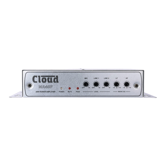
Page 14: Ront Pane Description
Down mode 7. MUTE – red LED: illuminates when the E function is acti e 8. PEAK – red LED: illuminates if the amplifier s dynamic clip protection ecomes acti e MA40F/MA40T Installation and User Guide v1. -
Page 15: Rear Pane Description
SPEA ER O TP T only – spea er output for low impedance circuits SPEA ER O TP T only – for connection to line loudspea er system MA40F/MA40T Installation and User Guide v1. - Page 16 D switch functions on page in the ppendi section for full details. 12. POWER INP T – connect e ternal D power here: the requires at . requires at . MA40F/MA40T Installation and User Guide v1.
-
Page 17: Insta Ation
10 mm 200 mm 0.4” 7.9” 10 mm 0.4” MA40F MA40F/MA40T Installation and User Guide v1. -
Page 18: Entilation
MA40F/MA40T Installation and User Guide v1. -
Page 19: Onnections And Ad Ustments
R L or L is in use the two line inputs are summed together internally though Line input can e con gured to ha e priority o er Line input see Line riority on page MA40F/MA40T Installation and User Guide v1. -
Page 20: Line Riority
Line . nce the signal at Line stops e.g. when an announcement nishes Line s source will smoothly restore to its former le el o er appro . seconds. MA40F/MA40T Installation and User Guide v1. - Page 21 . mm pitch screw terminal type on the rear panel . se the wiring shown elow. 70/100V LINE COLD SCREEN MA40F/MA40T Installation and User Guide v1.
- Page 22 FEED FROM 100 V LINE SPEAKER SYSTEM Alternative connection for 70 V line system shown in dashed lines 70/100V LINE MA40F/MA40T Installation and User Guide v1.
-
Page 23: Line Inputs
E the mic input operates as a typical loud paging input and D switch is ena led. n E mode the aging ccess contacts will need to e shorted in order for the mic input to ecome acti e. MA40F/MA40T Installation and User Guide v1. - Page 24 ACTIVATES PAGING COLD SCREEN Balanced mic input n either mode the music signal is faded ac up after the announcement is complete o er a period of appro . seconds. MA40F/MA40T Installation and User Guide v1.
- Page 25 . ee layout diagram on page for locations of umpers. MA40F/MA40T Installation and User Guide v1.
- Page 26 D switch should e left set to L L when is connected to the acility ort. he pinout of the acility ort connector is gi en in the ta le on the following page. MA40F/MA40T Installation and User Guide v1.
- Page 27 D ref for system music controls onnector shell tandard wiring for pre made ca les MA40F/MA40T Installation and User Guide v1.
-
Page 28: Line Input
. he module also includes the functions of a loud R L Remote ontrol late which allows remote control of the s music le el and selection of Line or Line as the music source. MA40F/MA40T Installation and User Guide v1. - Page 29 . his should e connected s ACI IT PORT with screened at ca le and shielded to the plugs. ull details can e found in the nstallation uide. MA40F/MA40T Installation and User Guide v1.
- Page 30 IGNORE ALL OTHER CORES RSL-6 REMOTE SOURCE & LEVEL CONTROL WIRING FACILITY PORT (RJ45) 5 6 7 WHITE + BROWN RSL-6 BROWN BROWN WHITE + BROWN Screened Cat 5 cable IGNORE ALL OTHER CORES MA40F/MA40T Installation and User Guide v1.
-
Page 31: Aging Control And Mic Priority
D oltage to pin and music le el y a D oltage at pin . he reference for oth controls is ia the screen of the shielded R connector. MA40F/MA40T Installation and User Guide v1. - Page 32 MA40F/MA40T Installation and User Guide v1.2...
- Page 33 . he alarm output must e olt free if no such output is a aila le an intermediate relay or other isolation de ice must e installed etween the alarm output and the usic ute input. MA40F/MA40T Installation and User Guide v1.2...
- Page 34 E modules are a aila le from loud Electronics to suit se eral popular ranges of installed sound loudspea ers please chec current module a aila ility at www.cloud.co.u accessories. MA40F/MA40T Installation and User Guide v1.2...
- Page 35 Replace the top co er. MA40F/MA40T Installation and User Guide v1.2...
- Page 36 DO NOT FIT A JUMPER HERE! EQ CARD SOCKET CON1 NOT TO SCALE. ONLY PRIMARY COMPONENTS SHOWN REAR OF UNIT MA40F/MA40T Installation and User Guide v1.2...
-
Page 37: Uto Ower Down
Music Mute card ypass resent a sent resent hi pass lter MA40T: ON or factory use only – do not t a sent umper here uto ower Down resent a sent resent phantom power MA40F/MA40T Installation and User Guide v1.2... -
Page 38: Ummary Of Rear Panel D Switch Functions
E mode disa led mode . MA40F/MA40T Installation and User Guide v1.2... - Page 39 L E and L E input signals are controlled y the two front panel LE EL controls. he two inputs are mi ed together. ote: default settings are in O D te t. MA40F/MA40T Installation and User Guide v1.2...
-
Page 40: E Considerations
MA40F/MA40T Installation and User Guide v1.2... -
Page 41: Echnical Speci Cations
ICROP ONE INP T requency Response lter to Distortion <0.1% d to nput mpedance ohms alanced eadroom Noise hantom ower internal umper O TP T utput ower D input continuous sine wa e MA40F/MA40T Installation and User Guide v1.2... - Page 42 Resetta le internal rea er no fuses . mm MA40F hipping Dimensions . mm MA40T hipping MA40F hipping eight MA40T hipping MA40F/MA40T Installation and User Guide v1.2...
- Page 43 MA40F/MA40T Installation and User Guide v1.
- Page 44 c o d co c o d sa ro...
Need help?
Do you have a question about the MA40T and is the answer not in the manual?
Questions and answers