Cloud MPA SERIES Installation And User Manual
Hide thumbs
Also See for MPA SERIES:
- Installation and user manual (16 pages) ,
- Installation and user manual (16 pages)
Table of Contents
Advertisement
Quick Links
Advertisement
Table of Contents

Subscribe to Our Youtube Channel
Related Manuals for Cloud MPA SERIES


Summary of Contents for Cloud MPA SERIES
- Page 1 MPA SERIES MIXER-AMPLIFIER Installation and User Guide...
- Page 2 The exclamation point within an equilateral triangle is intended to alert the user to the presence of important operating and maintenance (servicing) instructions in the literature accompanying the appliance. MPA Series User Manual v2.0...
-
Page 3: Important Safety Instructions
Class 2 Wiring, but voltages at these terminals may be of sufficient magnitude constitute a risk of electric shock. The external wiring connected to these terminals requires installation by an instructed person or the use of pre-made leads or cords. MPA Series User Manual v2.0... - Page 4 MPA Series User Manual v2.0...
-
Page 5: Table Of Contents
Chime ............11 Power Amplifier Stage and Outputs..12 Line Output ...............12 Low impedance operation ........12 High pass filter ............12 MOH/Utility Output ..........12 MOH/Utility Output ..........13 Auxiliary Output ............13 Music Mute (Fire Alarm Interface) .......14 MPA Series User Manual v2.0... -
Page 6: Safety Information
The product conforms to the following European electrical safety standard: BS EN 60065:2012 The MPA Series was developed and manufactured with high quality materials and components, which can be recycled and/or reused. The WEEE symbol indicates that electrical and electronic equipment... -
Page 7: General Description
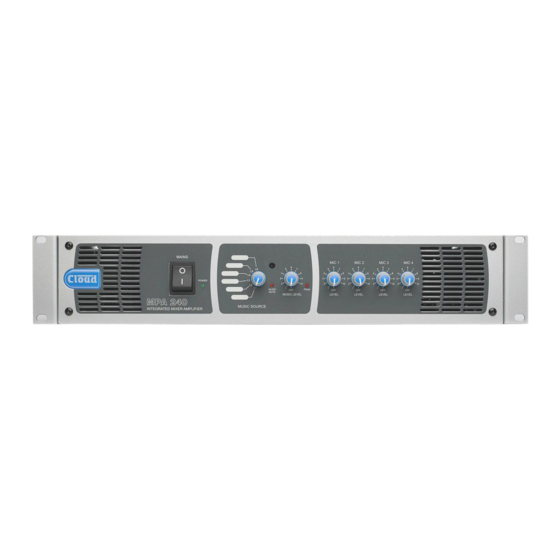
General Description The Cloud MPA Series is a range of mixer-amplifiers with applications in Licensed, Retail, Leisure and similar venues. Two models are available to suit different output power requirements (120 or 240 watts); otherwise both models have identical facilities. -
Page 8: Front Panel Description
LOW IMPEDANCE OUTPUT – speaker output IEC mains input for low-Z connection Mains fuse LINE OUTPUT – for connection of 100 V/ 70 V/25 V line distribution system Fan – forced-air cooling air exhaust MPA Series User Manual v2.0... -
Page 9: Music Inputs
Remote Control of Music Source Select and Level The unit has six stereo line inputs; these inputs are suitable The MPA Series mixer-amplifiers are compatible with for most music sources such as compact disc players, tape standard Cloud remote control plates: RSL-6 Series (music players, satellite receivers and the like. -
Page 10: Music Priority
MIC INPUTS PIN 1: SCREEN (GROUND) PIN 2: COLD/ANTIPHASE (-) PIN 3: HOT/PHASE (+) BALANCED CONNECTION UNBALANCED CONNECTION fig.5: Microphone Input Wiring MPA Series User Manual v2.0... -
Page 11: Using Mic 1 With A Telephone System
The gain controls on the rear panel (see Gain Control) should be set at a level where microphone distortion does MPA Series amplifiers have an internal pre-announcement not occur even when the front panel level controls are fully chime generator. The chime is triggered by the Microphone clockwise. -
Page 12: Power Amplifier Stage And Outputs
0 V. system, it is recommended that the system manual is MPA Series amplifiers are able to deliver their rated power consulted to check suitable audio levels and any other into a 4 ohm load, as follows: compatibility issues. -
Page 13: Moh/Utility Output
Priority” on page 10), the MOH/Utility output will switch pin 1: ground to Line 6 along with the main output if the input becomes pin 2: cold Unbalanced input active. pin 3: hot (e.g., phono) fig.7b: Unbalanced Wiring MPA Series User Manual v2.0... -
Page 14: Music Mute (Fire Alarm Interface)
Activation of the Music Mute is often via a relay mounted Installation Instructions close to the MPA Series amplifier, powered by the fire alarm control panel. Other arrangements may exist depending Refer to the PCB layout diagram (see fig.9) for the location... -
Page 15: General Notes
MPA Series amplifiers can be used. The 0 V rail of an MPA Series amplifier is directly coupled to the chassis ground. No interconnection problems should be Signal sources can be connected to several inputs as required,... -
Page 16: Technical Specifications
482.6 mm x 88 mm (2U) x 300 mm (+ connectors & knobs) (W x H x D) 19” x 3.5” x 11.8” (+ connectors & knobs) 10.5 kg MPA120 23.5 lbs Net weight 21.6 kg MPA240 48.3 lbs MPA Series User Manual v2.0... -
Page 17: Location Of Internal Jumpers, Etc
Mic 2 phantom power Mic 3 phantom power Mic 4 phantom power Mic 1 Access Input bypass Music Mute NO or NC J15 (A, B & C) Enable Mic 1 for telephone system MOH/Utility Output music source SELECTED MPA Series User Manual v2.0... - Page 18 MPA Series User Manual v2.0...
- Page 19 MPA Series User Manual v2.0...
- Page 20 www.cloudusa.pro...
Need help?
Do you have a question about the MPA SERIES and is the answer not in the manual?
Questions and answers