Table of Contents
Advertisement
SIMATIC SIMATIC SM331; AI 8x12 Bit Getting Started part 1: 4 -20mA
SIMATIC
SM331; AI 8x12 Bit Getting Started
part 1: 4 -20mA
Getting Started
11/2006
A5E00253410-02
______________
Preface
______________
Requirements
______________
Introduction
Mechanical setup of the
______________
example station
______________
Electrical connection
Configuration of the
______________
SIMATIC Manager
______________
Testing the user program
______________
Diagnostic interrupt
______________
Hardware interrupt
______________
Appendix
1
2
3
4
5
6
7
8
9
A
Advertisement
Table of Contents

Related Manuals for Siemens Simatic SM331


Summary of Contents for Siemens Simatic SM331
- Page 1 ______________ Preface SIMATIC SIMATIC SM331; AI 8x12 Bit Getting Started part 1: 4 -20mA ______________ Requirements ______________ Introduction SIMATIC Mechanical setup of the ______________ example station SM331; AI 8x12 Bit Getting Started ______________ Electrical connection part 1: 4 -20mA Configuration of the...
- Page 2 Trademarks All names identified by ® are registered trademarks of the Siemens AG. The remaining trademarks in this publication may be trademarks whose use by third parties for their own purposes could violate the rights of the owner.
-
Page 3: Table Of Contents
Table of contents Preface ..............................1-1 General ............................1-1 Requirements ............................2-1 Basics............................2-1 Introduction............................. 3-1 Example of an application......................3-1 Mechanical setup of the example station ....................4-1 Mounting the example station ....................4-1 Mounting of analog module components................... 4-3 4.2.1 General ............................ - Page 4 Table of contents Testing the user program........................7-1 Downloading system data and user program ................7-1 Visualization of the sensor values....................7-3 Analog value representation ...................... 7-8 Diagnostic interrupt..........................8-1 Reading diagnostic information from a PG ................8-1 General diagnostics ........................8-3 Channel dependent diagnostic interrupts ..................
-
Page 5: Preface
Preface General Purpose of the Getting Started The Getting Started gives you a complete overview of the commissioning of the analog module SM331. It assists you in the installation and configuration of the hardware of a 4- 20mA sensor and the configuration with SIMATIC S7 Manager. The intended readership of Getting Started is a novice with only basic experience in configuration, commissioning and servicing of automation systems. - Page 6 Preface 1.1 General SM331; AI 8x12 Bit Getting Started part 1: 4 -20mA Getting Started, 11/2006, A5E00253410-02...
-
Page 7: Requirements
Requirements Basics Basic Knowledge Required No special knowledge of the field of automation technology is required in order to understand the Getting Started guide. As the configuration of the analog module is done with the software STEP7, proficiency in STEP7 would be advantageous. Further information on STEP7 can be found in the electronic manuals that are supplied with STEP7. - Page 8 Requirements 2.1 Basics Software STEP7 Quantity Article Order number STEP7 Software version 5.2 or later, installed on the 6ES7810-4CC06-0YX0 programming device. The following current transducers can be used for the acquisition of analog signals: Current transducers Quantity Article Order number 2-Wire current transducer depending on the manufacturer...
-
Page 9: Introduction
Introduction Example of an application Overview You want to connect three analog inputs to your station. One of them should have a 2-wire current transducer and the other two should share a 4-wire current transducer. You need failure diagnostic capabilities and want two sensors to be able to trigger hardware interrupts. - Page 10 Introduction 3.1 Example of an application In the following sections you will be introduced to: ● Mechanical setup of the example station – General mounting instructions for S7-300 modules – Configuration of the SM331 for the two selected measurement transducer types ●...
-
Page 11: Mechanical Setup Of The Example Station
Mechanical setup of the example station Mounting the example station Overview The setup of the example station is divided into two steps. First, the setup of the power supply and the CPU is explained. After becoming acquainted with the analog module SM331, the mounting of it is described. - Page 12 Mechanical setup of the example station 4.1 Mounting the example station step Graphic controller Description Mounting the power supply: Hang the power supply on to the top end of the rail • Screw it tight to the rail underneath • Connect the bus connector (delivered with the SM331) to the left connector on the back of the CPU Mounting the CPU:...
-
Page 13: Mounting Of Analog Module Components
Mechanical setup of the example station 4.2 Mounting of analog module components Mounting of analog module components 4.2.1 General Overview Before the actual mounting of the SM331 the module has to be completed with a front connector and the desired measurement mode of the inputs is set. In this section, you will learn about: ●... -
Page 14: Components Of The Sm331
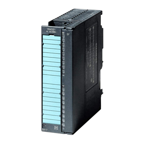
Mechanical setup of the example station 4.2 Mounting of analog module components 4.2.2 Components of the SM331 Overview A functional analog module consists of the following components: ● Module SM331 (in our example 6ES7331-7KF02-0AB0) ● 20-pin front connector There are two different types of front connectors: –... -
Page 15: Features Of The Analog Modules
Mechanical setup of the example station 4.2 Mounting of analog module components 4.2.3 Features of the analog modules Characteristics ● 8 inputs in 4 channel groups (each group with two inputs of same type) ● Measurement resolution adjustable for each channel group ●... -
Page 16: Measuring Range Modules
Mechanical setup of the example station 4.2 Mounting of analog module components 4.2.4 Measuring range modules Terminal The module SM331 has 4 measuring range modules (one per channel group). The measuring range modules can be set to 4 different positions (A, B, C or D). Figure 4-2 4 measuring range modules with default setting B (Voltage) SM331;... - Page 17 Mechanical setup of the example station 4.2 Mounting of analog module components Positions of the measuring range modules The position enables you to specify the transducer to be connected to the respective channel group. Position Type of measurement Thermocouple / resistance measurement Voltage (factory setting) Current (4-wire transducer) Current (2-wire transducer)
-
Page 18: Mounting The Sm331 Module
Mechanical setup of the example station 4.2 Mounting of analog module components Note When you use a 2-wire transducer, the electrical isolation against the load voltage is lost for all the channels in the module (at least one measuring range module is set to position D) 4.2.5 Mounting the SM331 module Proceed as follows... -
Page 19: Electrical Connection
Electrical connection Overview Overview This chapter shows you how the various parts of the example station are electrically wired from the power supply to the analog module. Warning You might get an electrical shock if the power supply PS307 is turned on or the power cord is connected to the line. -
Page 20: Wiring The Power Supply Module And The Cpu
Electrical connection 5.2 Wiring the power supply module and the CPU Wiring the power supply module and the CPU Overview Figure 5-1 Wiring the power supply module and the CPU SM331; AI 8x12 Bit Getting Started part 1: 4 -20mA Getting Started, 11/2006, A5E00253410-02... - Page 21 Electrical connection 5.2 Wiring the power supply module and the CPU The example station requires a power supply. The wiring is done as follows: Step Graphic controller Description Open the front panel covers of the power supply module and CPU. Unscrew the cable grip on the power supply Remove the insulation from the power cord, attach the cable end sleeves (for stranded conductors) and connect it to the...
-
Page 22: Wiring Of The Analog Module
Electrical connection 5.3 Wiring of the analog module Wiring of the analog module 5.3.1 Requirement General The wiring of an analog measurement transducer is depends on its type and not on the SM331 module. 5.3.2 Current transducer wiring - principle Options Depending on the current transducer you use, you have to modify the wiring of the power supply. -
Page 23: Wiring Of The Analog Module
Electrical connection 5.3 Wiring of the analog module Wiring principles of a 4-wire current transducer Unlike a 2-wire transducer, this transducer has its own power supply. Figure 5-3 Wiring: 4-Wire current transducer 5.3.3 Wiring of the analog module Tasks The wiring of the analog module consists of the following tasks: ●... - Page 24 Electrical connection 5.3 Wiring of the analog module SM331 Front connector wiring Figure 5-4 SM331 Front connector wiring Notice Possible destruction of the module! If you connect a defective 4-wire current transducer to an input, which is configured for a 2- wire transducer, the module may be destroyed! The required wiring tasks are explained below step-by-step: SM331;...
- Page 25 Electrical connection 5.3 Wiring of the analog module Proceed as follows Step Graphic Connecting-up Comment controller Open the front door of the SM331 The connection diagram is printed on the front flap Remove 6 mm of the insulation from the ends of the wires that go into the front connector.
-
Page 26: Test
Electrical connection 5.3 Wiring of the analog module 5.3.4 Test Proceed as follows If you want to test the wiring, you may now switch the power supply on. Do not forget to set the CPU to STOP (see the red circle) Figure 5-5 Successful wiring, CPU in position STOP If a red LED is lit, then there is an error in the wiring. -
Page 27: Configuration Of The Simatic Manager
Configuration of the SIMATIC Manager Creating a new STEP7 project 6.1.1 Creating a new project "New Project..." Wizard Use STEP7 V5.2 or later for configuring the new CPU 315-2 DP. Start SIMATIC Manager by clicking the "SIMATIC Manager" icon on your Windows Desktop and create a new project with the STEP7 "New Project"... - Page 28 Configuration of the SIMATIC Manager 6.1 Creating a new STEP7 project A project wizard introduction window appears. The wizard guides you through the procedure for creating a new project. Figure 6-2 Wizard "New Project", start The following must be specified during the creation procedure: ●...
-
Page 29: Cpu Selection
Configuration of the SIMATIC Manager 6.1 Creating a new STEP7 project 6.1.2 CPU selection Proceed as follows Choose the CPU 315-2DP for the example project. (You can also use our example for a different CPU. Select the appropriate CPU in this case.) Figure 6-3 "New Project"... -
Page 30: Defining The Basic User Program
Configuration of the SIMATIC Manager 6.1 Creating a new STEP7 project 6.1.3 Defining the basic user program Proceed as follows Choose the SIMATIC language STL and select the following organization blocks (OBs): ● OB1 cyclically executed block ● OB40 hardware interrupt ●... -
Page 31: Assigning The Project Name
Configuration of the SIMATIC Manager 6.1 Creating a new STEP7 project 6.1.4 Assigning the project name Proceed as follows Select the “Project name” text box and overwrite the name in it with “Getting Started S7 SM331”. Figure 6-5 "New Project" wizard: Assigning the project name Click "Finish". -
Page 32: Result S7 Project Is Created
Configuration of the SIMATIC Manager 6.1 Creating a new STEP7 project 6.1.5 Result S7 project is created Result The wizard has created the project “Getting Started S7-SM331”. You can see the inserted organization blocks in the right window. Figure 6-6 "New Project"... -
Page 33: Hardware Configuration
Configuration of the SIMATIC Manager 6.2 Hardware configuration Hardware configuration 6.2.1 Creating the hardware configuration Requirements The STEP7 wizard has created a basic S7 project. You also need a complete hardware configuration in order to create the system data for the CPU. Proceed as follows You can create the hardware configuration of the example station with SIMATIC Manager. -
Page 34: Adding Simatic Components
Configuration of the SIMATIC Manager 6.2 Hardware configuration 6.2.2 Adding SIMATIC components Proceed as follows First select a power supply module from the hardware catalog. If the hardware catalog is not visible, open it with the shortcut key Ctrl+K or by clicking the catalog icon (blue arrow). - Page 35 Configuration of the SIMATIC Manager 6.2 Hardware configuration Inserting an analog module There are many SM331 analog modules. For this project we use an SM331, AI8x12 bit with the order number 6ES7 331-7KF02-0AB0. The order number is displayed at the bottom of the hardware catalog (see blue arrow). Figure 6-9 Hardware configuration: SM331 insert Drag the module into the first available field at slot 4 of your rack (see red arrow).
-
Page 36: Configuring The Analog Module
Configuration of the SIMATIC Manager 6.2 Hardware configuration 6.2.3 Configuring the analog module Overview SIMATIC Manager inserts the analog module with its default settings. You can modify the parameters to change the sensor types, diagnostics and interrupt capabilities. Mounting the example station The table shows, which parameters have to be set for our example station. - Page 37 Configuration of the SIMATIC Manager 6.2 Hardware configuration Opening the configuration Double-click on slot 4 that has the SM331 in it. Select the "Inputs" tab. Configure the following functions: ● Diagnostic interrupt enabled ● Hardware interrupt enabled ● Input 0-1: –...
- Page 38 Configuration of the SIMATIC Manager 6.2 Hardware configuration Explanation of the individual settings Measuring type: 2DMU and 4DMU stand for 2-wire and 4-wire current transducers --- means that the channels are deactivated. If you deactivate channels, the remaining channels are processed faster. Measuring range modules The required setting of the measuring range module is displayed.
-
Page 39: Test
Configuration of the SIMATIC Manager 6.2 Hardware configuration 6.2.4 Test Proceed as follows For testing, do a power up test and download the system data. Step Graphic controller Description Erase your Micro Memory Card with a Power PG or a PC with external programming device: In SIMATIC Manager click "File ->... - Page 40 Configuration of the SIMATIC Manager 6.2 Hardware configuration Downloading hardware configuration Download the hardware configuration into the CPU with HW Config. Figure 6-11 Download CPU hardware configuration (1) SM331; AI 8x12 Bit Getting Started part 1: 4 -20mA 6-14 Getting Started, 11/2006, A5E00253410-02...
- Page 41 Configuration of the SIMATIC Manager 6.2 Hardware configuration Click the "Load to module" icon (shown in the red circle). When the dialog window "Select target module" appears, click OK. Figure 6-12 Download CPU hardware configuration (2) The dialog window "Select target address" is shown. Click "OK." The system data will now be transferred to the CPU.
- Page 42 Configuration of the SIMATIC Manager 6.2 Hardware configuration Starting the CPU Switch the CPU to RUN. If the hardware configuration was undertaken correctly, two red LEDs (RUN and DC5V) should be lit on the CPU. Figure 6-13 CPU in error free state SM331;...
-
Page 43: Step 7 User Program
Configuration of the SIMATIC Manager 6.3 STEP 7 user program STEP 7 user program 6.3.1 Tasks of the user program Overview In our example, the sensor values are stored in a data block. Also, the hardware interrupt status should be stored in a marker word. It should be possible to acknowledge the status information by means of a bit. -
Page 44: Creating A User Program
Configuration of the SIMATIC Manager 6.3 STEP 7 user program 6.3.2 Creating a user program Proceed as follows There are two ways to create a user program. ● If you know how to program STEP7 SCL, then you can create and program the necessary blocks and the function blocks in the Blocks folder of STEP7. - Page 45 Configuration of the SIMATIC Manager 6.3 STEP 7 user program Importing a source file You can import the source file into SIMATIC Manager as follows: Right click the folder "Sources". Select "Insert new Object > External Source...". Figure 6-14 Importing an external source SM331;...
- Page 46 Configuration of the SIMATIC Manager 6.3 STEP 7 user program In the "Insert external source" dialog browse for the source file GSSM331T1DE.AWL, which you have already downloaded and saved on your hard disk. Select the source file GSSM331T1DE.AWL (red arrow). Figure 6-15 Importing an external source SM331;...
- Page 47 Configuration of the SIMATIC Manager 6.3 STEP 7 user program Click "Open". SIMATIC Manager has opened the source file. In the right window you can see the source file inserted. Figure 6-16 Compiling the source code SM331; AI 8x12 Bit Getting Started part 1: 4 -20mA Getting Started, 11/2006, A5E00253410-02...
- Page 48 Configuration of the SIMATIC Manager 6.3 STEP 7 user program Compiling the source code In order to create an executable STEP7 program, the STL source has to be compiled. Double-click the source file GSSM331T1DE in the Sources folder. The source code editor opens.
- Page 49 Configuration of the SIMATIC Manager 6.3 STEP 7 user program After the source code is loaded, start the compilation. Press the shortcut key Ctrl+B or select File > Compile. The compilation starts immediately. Figure 6-18 Compiling STL source SM331; AI 8x12 Bit Getting Started part 1: 4 -20mA Getting Started, 11/2006, A5E00253410-02...
- Page 50 Configuration of the SIMATIC Manager 6.3 STEP 7 user program In case of warning or error messages, check the source code. Figure 6-19 Source code editor, messages after compilation SM331; AI 8x12 Bit Getting Started part 1: 4 -20mA 6-24 Getting Started, 11/2006, A5E00253410-02...
- Page 51 Configuration of the SIMATIC Manager 6.3 STEP 7 user program Close the source code editor. After compiling the STL source without errors the following blocks should appear in the Blocks folder: OB1, OB40, OB82, FC1, DB1 and DB2 Figure 6-20 Generated blocks SM331;...
- Page 52 Configuration of the SIMATIC Manager 6.3 STEP 7 user program SM331; AI 8x12 Bit Getting Started part 1: 4 -20mA 6-26 Getting Started, 11/2006, A5E00253410-02...
-
Page 53: Testing The User Program
Testing the user program Downloading system data and user program Proceed as follows The hardware and software are now ready. The next step is to download the system data and the user program into the automation system. To do this, proceed as follows: Downloading the system data and user program Step Graphic controller... - Page 54 Testing the user program 7.1 Downloading system data and user program Smart Label The labeling strips for the modules were created with Siemens S7 Smart Label (order no: 2XV9 450-1SL01-0YX0). A labeling strip in its actual size: Figure 7-1 S7-SmartLabel labeling strip for the example SM331;...
-
Page 55: Visualization Of The Sensor Values
Testing the user program 7.2 Visualization of the sensor values Visualization of the sensor values Proceed as follows In order to visualize the sensor values, insert a variable table as follows into the project. To do this, select from the context menu of the Blocks folder: Insert new object >... - Page 56 Testing the user program 7.2 Visualization of the sensor values Fill the new variable table as follows: In this area you can monitor the channel values In this area you can see the analog values In this area you can monitor and control the status signals SM331;...
- Page 57 Testing the user program 7.2 Visualization of the sensor values Variable description Variables Description DB1.DBW 0 Channel 0 Display of analog value DB1.DBW 2 Channel 1 Display of analog value DB1.DBW 4 Channel 2 Display of analog value DB1.DBW 6 Channel 3 Display of analog value DB1.DBW 8 Channel 4 Display of analog value...
- Page 58 Testing the user program 7.2 Visualization of the sensor values Monitoring values In order to monitor values, open the online view of the controller by clicking the eye glasses symbol. Now you can monitor the values in the data blocks and markers. Figure 7-3 Online view of the variable table Channel values in hex format...
- Page 59 Testing the user program 7.2 Visualization of the sensor values Controlling values To control the process acknowledgement, enter the desired value (TRUE or FALSE, depending on whether you want to activate or deactivate acknowledgement) into the column "Control Value" and click the icon with the two arrows. Controlling variables Channel value Analog value...
-
Page 60: Analog Value Representation
Testing the user program 7.3 Analog value representation Analog value representation Proceed as follows The analog values are only processed by the CPU in binary form. Analog input modules convert the analog process signal into a digital format (16 bit word). Five ranges have to be taken into account when converting from digital to analog values: Representation of analog values in current measuring ranges 4 to 20 mA Hex value... -
Page 61: Diagnostic Interrupt
Diagnostic interrupt Reading diagnostic information from a PG Overview Diagnostic interrupts enable the user program to react to hardware errors. Modules must have diagnostic capabilities in order to generate diagnostic interrupts. In OB82 you program the reaction to diagnostic interrupts. Display The analog input module SM331 AI8x12 has diagnostic capabilities. - Page 62 Diagnostic interrupt 8.1 Reading diagnostic information from a PG The cause of the error can be determined "online" by requesting the hardware status. In order to determine the state of module "online", proceed as follows: Select the SM331 in the hardware configuration. Click the menu command CPU -> Module Information...
-
Page 63: General Diagnostics
Diagnostic interrupt 8.2 General diagnostics General diagnostics Diagnostic interrupt tab On the Diagnostic Interrupt tab you will find information for the reported error. The interrupts are not channel dependent and apply to the entire module. Figure 8-3 Diagnostics for SM331 SM331;... -
Page 64: Channel Dependent Diagnostic Interrupts
Diagnostic interrupt 8.3 Channel dependent diagnostic interrupts Channel dependent diagnostic interrupts 8.3.1 There are five channel dependent diagnostic interrupts There are five channel dependent diagnostic interrupts: ● Configuration / programming error ● Common mode error ● Wire break ● Underflow ●... -
Page 65: Wire Break
Diagnostic interrupt 8.3 Channel dependent diagnostic interrupts 8.3.4 Wire break Meaning If wire break detection is enabled for 2-wire transducers, there will be no direct check for a wire break. The diagnostics instead reacts on the shortfall of the low limit current value. With 4 to 20 mA current transducer, the diagnostic message “Analog input wire break“... -
Page 66: Overflow
Diagnostic interrupt 8.3 Channel dependent diagnostic interrupts 8.3.6 Overflow Meaning If the current exceeds 22.81 mA, an overflow message stating "Analog in-put measuring range / High limit exceeded" is displayed. The display of the analog value (HEX 7FFF) is in the overflow range. Figure 8-5 Left: Diagnostic message with overflow / Right: Variable table Note... -
Page 67: Hardware Interrupt
Hardware interrupt Hardware interrupt Overview A special feature of the SM331 AI8x12bit is its capability to trigger hardware interrupts. Two channels (0 and 2) can be correspondingly configured. Hardware interrupts generally trigger alarm organization blocks in the CPU. In our example, OB40 is called. - Page 68 Hardware interrupt 9.1 Hardware interrupt Determining functions If a hardware interrupt occurs, OB40 is called. In the user program of OB40 you can program the reaction of the automation system to hardware interrupts. In the example user program, OB40 reads the cause of the hardware interrupt. This can be found in the temporary variable structure OB40_POINT_ADDR (local words 8 to 11).
-
Page 69: Appendix
Appendix Source of the user program STL source code In this section you find the source code of the user program from the example. You can download the source file directly from the HTML page from which you loaded this "Getting Started". -
Page 70: A.1 Source Of The User Program
Appendix A.1 Source of the user program END_DATA_BLOCK FUNCTION FC 1 : VOID TITLE =Conversion of a channel’s raw values in mA VERSION : 1.0 VAR_INPUT Raw : WORD ; // Analog value display END_VAR VAR_OUTPUT Current : REAL ; // Current in mA END_VAR VAR_TEMP... - Page 71 Appendix A.1 Source of the user program END_VAR BEGIN NETWORK TITLE =Read channels // Channel values 0 to 7 are loaded and stored in DB1 (channel values) PEW 256; //Channel 0 DB1.DBW PEW 258; //Channel 1 DB1.DBW PEW 260; //Channel 2 DB1.DBW PEW 262;...
- Page 72 Appendix A.1 Source of the user program 200.0; SPBN lbl0; 100; 100; lbl0: NOP NETWORK TITLE =The End END_ORGANIZATION_BLOCK ORGANIZATION_BLOCK OB 40 TITLE = "Hardware Interrupt" // Processing OB40_POINT_ADDR (L8 to L11) //L8 High limit value exceeded //L9 Low limit value exceeded VERSION : 1.0 VAR_TEMP OB40_EV_CLASS : BYTE ;...
- Page 73 Appendix A.1 Source of the user program L002: NETWORK TITLE =Sensor 2 (Channel 2): Lower limit value 9.2; // Channel 2 low limit value SPBNB L003; W#16#4; 100; 100; L003: NETWORK TITLE =Sensor 2 (Channel 2): Upper limit value 8.2; // Channel 2 upper limit value SPBNB L004;...
- Page 74 Appendix A.1 Source of the user program SM331; AI 8x12 Bit Getting Started part 1: 4 -20mA Getting Started, 11/2006, A5E00253410-02...
-
Page 75: Index
Index Check Line voltage, 5-3 Clear / Reset, 6-13 Common mode error, 8-4 2-Wire current transducer Components wiring principle, 5-4 SM331, 4-4 Components of the Product SM331 modules, 4-4 Configuration 4-Wire current transducer Calling, 6-11 wiring principle, 5-5 Configuration / programming error, 8-4 Configuration language STL, 6-4 Configuring... - Page 76 Index Hardware configuration calling, 6-7 Define the basic user program Configuring, 6-7 Defining, 6-4 Downloading, 6-14 Defining Finishing, 6-12 Defining the basic user program, 6-4 Hardware fault Functions in event of hardware interrupts, 9-2 find, 8-2 Delete Hardware interrupt Micro memory card, 6-13 limit values, 9-1 Diagnostic functionality, 5-7 Hardware interrupt, 6-12, 9-1...
- Page 77 Index Micro memory card Sensor values Deleting, 6-13 Visualize, 7-3 Monitoring Settings Values, 7-6 Parameters, 6-10 Mounting rail test, 6-13 screw, 4-1 SIMATIC Manager, 6-1 Hardware configuration, 6-7 start, 6-1 SM331 Components, 4-4 OB82, 6-17 Installing, 4-8 Organization blocks SM331 Front connector Selecting, 6-4 Wiring, 5-7 Overflow, 8-6...
- Page 78 Index Visualize Sensor values, 7-3 Underflow, 8-5 User Program Creating, 6-18 source code, A-1 Structure, 6-17 Wire break, 8-5 Testing, 7-1 Wiring Analog module, 5-4, 5-5 SM331 Front connector, 5-7 Wiring the power supply and CPU, 5-2 Wiring principle Values 2-Wire current transducer, 5-4 Controlling, 7-7 4-Wire current transducer, 5-5...
Need help?
Do you have a question about the Simatic SM331 and is the answer not in the manual?
Questions and answers