Table of Contents
Advertisement
SIMATIC
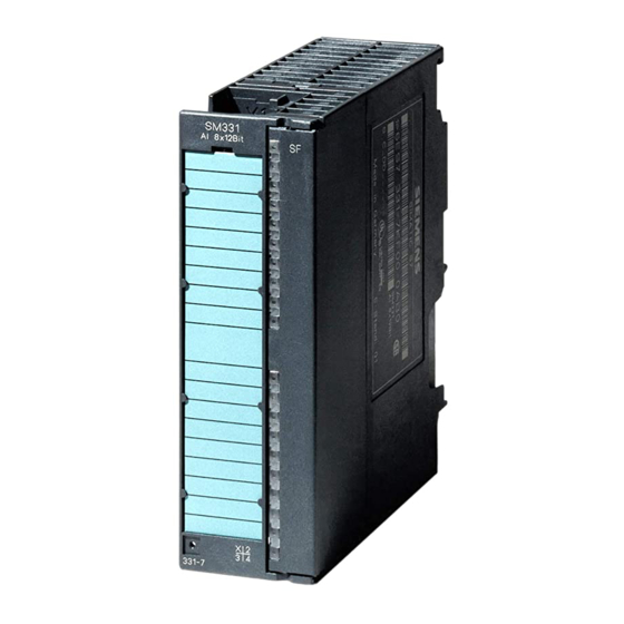
SM331; AI 8 x 12 Bit
Getting Started
Part 1: 4-20mA
Edition 09 / 2003
A5E00253410
Preface
Requirements
Task
Mechanical setup of the sample
station
Electrical connection
Configuration with
SIMATIC Manager
Test the user program
Diagnostic interrupt
Hardware interrupt
Source Code of the user Program
Advertisement
Table of Contents

Related Manuals for Siemens Simatic SM331


Summary of Contents for Siemens Simatic SM331
- Page 1 Preface Requirements SIMATIC Task Mechanical setup of the sample station SM331; AI 8 x 12 Bit Electrical connection Getting Started Configuration with Part 1: 4-20mA SIMATIC Manager Test the user program Diagnostic interrupt Hardware interrupt Source Code of the user Program Edition 09 / 2003 A5E00253410...
- Page 2 Registered Trademarks SIMATIC®, SIMATIC HMI® and SIMATIC NET® are registered trademarks of Siemens AG. Third parties using for their own purposes any other names in this document which refer to trademarks might infringe upon the rights of the trademark owners.
-
Page 3: Table Of Contents
Contents: Preface ......................3 Requirements ..................... 4 Required basic knowledge ................4 Required Hardware and Software..............4 Task ......................6 Mechanical setup of the sample station ..........8 Mounting the sample station ................ 8 Mounting the analog module..............10 4.2.1 Components of the SM331 ................ - Page 4 8.3.3 Wire break....................49 8.3.4 Underflow ....................49 8.3.5 Overflow ..................... 49 Hardware interrupt ................... 51 Source code of the user program............53 Getting Started SM331 AI 8x12bit Part1: 4-20mA A5E00253410...
-
Page 5: Preface
Preface Purpose of the Getting Started The Getting Started gives you a complete overview of the commissioning of the analog module SM331. It assists you in the installation and parameteri- zation of the hardware of a 4-20mA sensor and the configuration with SIMATIC S7 Manager. -
Page 6: Requirements
Requirements Required basic knowledge No special knowledge in the area of automation technique is required to understand this description. As the configuration of the analog module is done with the software STEP7, proficiency in STEP7 would be advanta- geous. Further information on STEP7 can be found in the electronic manuals that were delivered with STEP7. - Page 7 The following current transducers can be used for the acquisition of analog signals: Table 2-4 Current transducers Quantity Article Order number 2-Wire current transducer Depending on the manufacturer 4-Wire current transducer Depending on the producer Note This „Getting Started“ describes only the application of 4 – 20 mA current trans- ducers in the 2-Wire or 4-Wire model.
-
Page 8: Task
Task You want to connect three analog inputs to your station. One of them should have a 2-wire current transducer and the other two share a 4-wire current transducer. You need failure diagnostic capabilities and want two sensors to be able to trigger hardware interrupts. - Page 9 You will be guided through these steps • Mechanical setup of the sample station (see chapter 4) General mounting instructions for S7-300 modules Configuration of the SM331 for the two selected measure- ment transducer types • Electrical wiring of the sample station (see chapter 5) Wiring of the power supply and the CPU Wiring of the analog module Standard pin layout of two measurement transducer types...
-
Page 10: Mechanical Setup Of The Sample Station
Mechanical setup of the sample station The setup of the sample station is divided into two steps. First, the setup of the power supply and the CPU is explained. After becoming acquainted with the analog module SM331 the mounting of it is described. Mounting the sample station Before you can use the analog input module SM331, you need a basic setup of general SIMATIC S7-300 components. - Page 11 Graphics Description Connect the bus connector (delivered with the SM331) to the left connector on the back of the CPU Mounting the CPU: • Hang the CPU to the top end of the rail • Push it all the way left to the power supply •...
-
Page 12: Mounting The Analog Module
Mounting the analog module Before the actual mounting of the SM331 the module has to be completed with a front connector and the desired measurement mode of the inputs is set. In this section you will learn • Which components you need •... -
Page 13: Properties Of The Analog Module
Table 4-2 The scope of delivery of SM331 Components Module Labeling strips Bus connector 2 cable ties (not in the picture) to tie the external wiring 4.2.2 Properties of the analog module • 8 inputs in 4 channel groups (each group with two inputs of same type) •... -
Page 14: Measuring Range Modules
4.2.3 Measuring range modules The module SM331 has four measuring range modules (one per channel group). The measuring range modules can be set to 4 different positions (A, B, C or D). With the set position you determine which transducer can be connected to the respective channel group. - Page 15 In our example, a sensor with a 4 to 20mA 2-wire transducer is connected to channel group 1 at input 0. A 4-wire transducer is connected to channel group 2 at inputs 2 and 3. Therefore, the first measuring range module should have Position D and the second should have Position C Table 4-4 Positioning of the measuring range modules...
-
Page 16: Mounting The Sm331 Module
4.2.4 Mounting the SM331 module After you have prepared the analog module accordingly, mount it to the rail as well. Table 4-5 Mounting the SM331 module Graphics Description Mounting the SM331: • Insert the SM331 to the top part of the rail •... -
Page 17: Electrical Connection
Electrical connection This chapter shows you how the various parts of the sample station are electrically wired from the power supply to the analog module. Warning You might get an electrical shock if the power supply PS307 is turned on or the power cord is connected to the line. - Page 18 The sample station requires a power supply. The wiring is done as follows: Table 5-1 Wiring the power supply and the CPU Step Graphics Description Open the front flaps of the power supply and the CPU Unscrew the pull relief bracket on the power supply Remove the insulation from the power cord, attach the cable end sleeves (for multi-wire cords) and connect it to the power supply...
-
Page 19: Wiring The Analog Module
Wiring the analog module The wiring of an analog measurement transducer is dependant on its type and not on the SM331 module. 5.2.1 Current transducer wiring - Principle Depending on the current transducer you use, you have to modify the wir- ing of the power supply. -
Page 20: Wiring Of The Analog Module
5.2.2 Wiring of the analog module The wiring of the analog module consists of the following tasks: • Connection of the power supply (Red cable) • Connection of the 2-wire current transducer (Green cables) • Terminate unused channels with a resistor •... - Page 21 Step by step the tasks necessary for wiring are explained below: Table 5-2 SM331 Front connector wiring Graphics Wiring Comments Open the front flap of the SM331 The connection diagram is printed on the front flap Remove 6 mm of the insulation from the ends of the wires that go into the front con- nector.
-
Page 22: Switch On Now
5.2.3 Switch on now If you want to test the wiring, you may now switch the power supply on. Do not forget to set the CPU to STOP (see the red circle) Figure 5-5 Successful wiring, CPU in position STOP If a red LED is lit, then there is an error in the wiring. -
Page 23: Configuration With Simatic Manager
Configuration with SIMATIC Manager In this chapter the following tasks are executed: • Creating a new STEP7 project • Parameterization of the hardware configuration Create a new STEP7 Project Use STEP7 V5.2 or later version for configuring the new CPU 315-2 DP. Start SIMATIC Manager by clicking the symbol „SIMATIC Manager“... - Page 24 An introduction window pops up. The wizard will guide you through the creation of a new project. Figure 6-2 STEP7 wizard „New Project“, start During the creation the following inputs are necessary: • Selection of the CPU • Define the basic user program •...
-
Page 25: Cpu Selection
6.1.1 CPU Selection Choose the CPU 315-2DP for the sample project. (You can also use our example for a different CPU). Then choose your CPU. Figure 6-3 STEP7 wizard „New Project“, CPU selection Click „Next“ 6.1.2 Define the basic user program Choose the SIMATIC language STL and select the following organization blocks (OBs): •... -
Page 26: Specify The Project Name
6.1.3 Specify the project name Select the edit field “Project name” and overwrite the name in it with “Get- ting Started S7 SM331” Figure 6-5 STEP7 wizard „New Project“: Specify project name Click „Finish“. The basic STEP7 project is created automatically. 6.1.4 Resulting S7 project is created The wizard has created the project “Getting Started S7-SM331”. -
Page 27: Hardware Configuration
Hardware configuration The STEP7 wizard has created a basic S7 project. You also need a com- plete hardware configuration in order to create the system data for the CPU. 6.2.1 Create the hardware configuration You can create the hardware configuration of the sample station with SIMATIC Manager. -
Page 28: Insert Simatic Components
6.2.2 Insert SIMATIC components First select a power supply module from the hardware catalog. If the hardware catalog is not visible, open it with the shortcut key Ctrl+K or by clicking the catalog symbol (blue arrow). In the hardware catalog you can browse through the folder SIMATIC 300 to the folder PS-300. - Page 29 Insert analog module There are many SM331 analog modules. For this project we use an SM331, AI8x12 Bit with the order number 6ES7 331-7KF02-0AB0. The order number is displayed at the bottom of the hardware catalog (blue arrow). Figure Hardware configuration: Insert SM331 Order number of the module Drag the module into the first available field at slot 4 of your rack (see red arrow).
-
Page 30: Parameterization Of The Analog Module
6.2.3 Parameterization of the analog module SIMATIC Manager inserts the analog module with its standard settings. You can modify the parameters to change the sensor types, diagnostics and interrupt capabilities. Functionality of the sample station The table shows, which parameters have to be set for our sample station. Table 6-1 SM331 Functionality of the sample station Functionalities... - Page 31 • Interference frequency: o Select your power frequency (50 Hz or 60 Hz) • Trigger for Hardware Interrupt o High limit 18 mA o Low Limit 6 mA Figure 6-10 SM331: Parameterization Explanation of the individual settings Measuring type: 2DMU and 4DMU stand for 2-wire and 4-wire current transducers --- means that the channels are deactivated.
- Page 32 Interference frequency (Interference frequency suppression) The frequency of the AC power supply network can interfere with the measurement values, especially in low voltage ranges and when thermo- couples are used. With this parameter you specify the frequency of your power supply on site. This parameter also influences the granularity, integration time and the ba- sic execution period of the channel group.
-
Page 33: Power Up Test
6.2.4 Power up test For testing, do a power up test and download the system data. Power up Table 6-3 Power up Image Description Erase your Micro Memory Card with a Power PG or a PC with external pro- gramming device: In SIMATIC Manager click “File # S7 Memory Card # Delete …”... - Page 34 Download hardware configuration Download the hardware configuration into the CPU with HW Config. Figure 6-11 Download the CPU’s hardware configuration (1) Click the symbol „Load to module“ (shown in the red circle). When the dialog window „Select target module“ pops up, click ok. Figure 6-12 Download the CPU’s hardware configuration (2) The dialog window „Select target address”...
- Page 35 Start CPU Set the CPU to RUN mode. If the hardware configuration was done correctly, two red LEDs (RUN and DC5V) should be lit at the CPU Figure 6-13 CPU in error free state Getting Started SM331 AI 8x12bit Part1: 4-20mA A5E00253410...
-
Page 36: Step7 User Program
STEP7 user program 6.3.1 Function of the user program In our example the input values are stored in a data block. Also, the hard- ware interrupt status should be stored in a marker word. It should be possi- ble to acknowledge the status information by means of a bit. Furthermore the channel values (values of the input words) should be stored in another data block. -
Page 37: Create User Program
6.3.2 Create user program There are two ways to create a user program. o If you know how to program STEP7 SCL, then you can create and pro- gram the necessary blocks and the function blocks in the Blocks folder of STEP7. - Page 38 Import source file You can import the source file into SIMATIC Manager as follows: • Right click the folder „Sources“ • Select „Insert new Object“ # External Source... Figure 6-14 Import external source In the dialog window „Insert external source“ browse for the source file GSSM331T1DE.AWL, which you have already downloaded and saved on your hard drive.
- Page 39 SIMATIC Manager has opened the source file. On the right pane you can see the source file inserted. Figure 6-16 Storing the source file Compile source code In order to create an executable STEP7 program, the STL source has to be compiled.
- Page 40 After the source code is loaded, start the compilation. Press the shortcut key Ctrl+B or select File # Compile. The compilation starts immediately. Figure 6-18 Translation of the STL source In case of warning or error messages, check the source code. Figure 6-19 Source code editor, messages after compilation Close the source code editor.
- Page 41 After compiling the STL source without errors the following blocks should appear in the Blocks folder: OB1, OB40, OB82, FC1, DB1 and DB2 Figure 6-20 Generated blocks Getting Started SM331 AI 8x12bit Part1: 4-20mA A5E00253410...
-
Page 42: Test The User Program
Test the user program Download system data and user program Hardware and software are ready now. The next step is to download the system data and the user program into the automation system. To do this, execute the following steps: Table 7-1 Download user program and system data Step... - Page 43 S7-SmartLabel The labeling strips for the modules were created with Siemens S7-SmartLabel (Or- der no.: 2XV9 450-1SL01-0YX0). The original size of the is displayed in Figure 7-1. Figure 7-1 S7-SmartLabel labeling strip for the example Getting Started SM331 AI 8x12bit Part1: 4-20mA...
-
Page 44: Visualization Of The Sensor Signals
Visualization of the sensor signals In order to visualize the sensor signals, insert a variable table as follows into the project. To do this, select from the context menu of the Blocks folder: Insert new object # Variable Table Figure 7-2 Insert Variable Table Fill the new variable table as follows: In this area you can... - Page 45 Table 7-2 Description of the variables Variable Description DB1.DBW 0 Channel 0 Display of analog value DB1.DBW 2 Channel 1 Display of analog value DB1.DBW 4 Channel 2 Display of analog value DB1.DBW 6 Channel 3 Display of analog value DB1.DBW 8 Channel 4 Display of analog value DB1.DBW 10...
- Page 46 Modification of variables For modifying the Process Control Acknowledgement enter the desired value (TRUE or FALSE) into the column „Modify Value“. The value de- pends on whether you want to activate or deactivate the acknowledgement. Click the symbol with the two arrows. Channel value Analog value Status...
-
Page 47: Display Of Analog Values
Display of analog values The CPU can only process analog values in binary format. Analog input modules convert the analog process signal into a digital format (16 bit word). Five ranges have to be taken into account when converting from digital to analog values: Table 7-3 Display of analog value in the current range 4 to 20 mA... -
Page 48: Diagnostic Interrupt
Diagnostic interrupt Diagnostic interrupts enable the user program to react on hardware fail- ures. Modules must have diagnostic capabilities in order to be able to generate diagnostic interrupts. In OB82 you program the reaction on diagnostic interrupts. Read diagnostic data from a PG The analog input module SM331 AI8x12 has diagnostic capabilities. -
Page 49: General Hardware Interrupt
In order to determine this, do the following: Select the SM331 in the hardware configuration. Click the menu item CPU - # Module Information... in order to perform a hardware diagnosis. Figure 8-2 Module Information General hardware interrupt On the Hardware Interrupt tab you find information for the failure reported. The interrupts are not channel dependent and apply to the entire module. -
Page 50: Channel Dependent Diagnostic Interrupts
Channel dependent diagnostic interrupts There are five channel dependent diagnostic interrupts: • Configuration or parameterization errors • Common mode error • Wire break • Underflow • Overflow Note Here we show you only the channel specific diagnosis for the measuring modes 2- 4-wire current transducers. -
Page 51: Wire Break
8.3.3 Wire break If wire break detection is activated for 2-wire transducers, there will be no direct check for a wire break. The diagnostics rather reacts on the shortfall of the low limit current value. For a 4 to 20 mA current transducer a diagnostic message “Analog input wire break“... - Page 52 Figure 8-5 Left: Diagnostic message with overflow / Right: Variable table Note Disabled channels also have 7FFF hex as the analog display value. Getting Started SM331 AI 8x12bit Part1: 4-20mA A5E00253410...
-
Page 53: Hardware Interrupt
Hardware interrupt A special feature of the SM331 AI8x12bit is its capability to trigger hard- ware interrupts. Two channels (0 and 2) can be configured that way. Hardware interrupts generally trigger alarm organization blocks. In our ex- ample OB40 is called. The limit values for hardware interrupts have to be specified in mA. - Page 54 Figure 9-2 Hardware interrupt: Channel 0 exceeded low limit value Getting Started SM331 AI 8x12bit Part1: 4-20mA A5E00253410...
-
Page 55: Source Code Of The User Program
Source code of the user program In this chapter you find the source code of the user program from the ex- ample. You can also download the source as an STL file directly from the HTML page from which you have loaded this “Getting started” (see chapter 6.3.2). STL source code DATA_BLOCK DB 1 TITLE =Analog module channel values... - Page 56 SE_3 := 0.000000e+000; END_DATA_BLOCK FUNCTION FC 1 : VOID TITLE = Conversion of a channel’s raw values VERSION : 1.0 VAR_INPUT Raw : WORD ; // Analog value display END_VAR VAR_OUTPUT Current : REAL ; // Current in mA END_VAR VAR_TEMP TDoubleInt : DINT ;...
- Page 57 ORGANIZATION_BLOCK OB 1 TITLE = "Main Program Sweep (Cycle)" VERSION : 1.0 VAR_TEMP OB1_EV_CLASS : BYTE ; //Bits 0-3 = 1 (Coming event), Bits 4-7 = 1 (Event class 1) OB1_SCAN_1 : BYTE ; //1 (Cold restart scan 1 of OB 1), 3 (Scan 2-n of OB OB1_PRIORITY : BYTE ;...
- Page 58 NETWORK TITLE = Conversion // Conversion of the channel’s raw data into current values (mA) CALL FC := DB1.DBW Current := DB2.DBD CALL FC := DB1.DBW Current := DB2.DBD CALL FC := DB1.DBW Current := DB2.DBD NETWORK TITLE = Reset hardware interrupt // Even though the hardware interrupt was reset by the hardware upon termi- nating OB40, // the value of the hardware interrupt must be reset manually...
- Page 59 OB40_STRT_INF : BYTE ; //16#41 (OB 40 has started) OB40_PRIORITY : BYTE ; //Priority of OB Execution OB40_OB_NUMBR : BYTE ; //40 (Organization block 40, OB40) OB40_RESERVED_1 : BYTE ; //Reserved for system OB40_IO_FLAG : BYTE ; //16#54 (input module), 16#55 (output module) OB40_MDL_ADDR : WORD ;...
- Page 60 8.2; // Channel 2 high limit SPBNB L004; W#16#8; 100; 100; L004: NOP NETWORK TITLE = Sensor 3 (Channel 3): Low limit // Only for demonstration purposes; Channel 3 has now hardware interrupt ca- pabilities. 9.3; // Channel 3 low limit SPBNB L005;...