Table of Contents
Advertisement
Product Information on the Reference Manual
Programmable Logic Controllers S7-300 Module Data Release 3
1
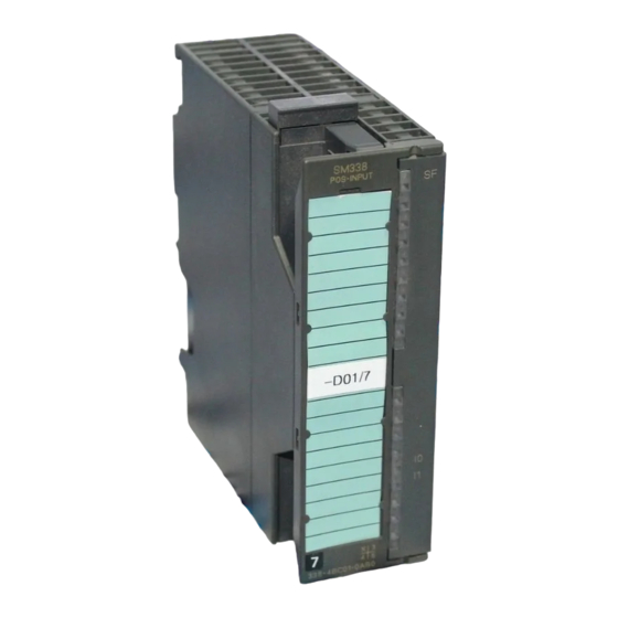
Position Decoder Module SM 338; POS-INPUT;
(6ES7338-4BC01-0AB0)
Order number
6ES7338-4BC01-0AB0
Characteristics
The position decoder module SM 338; POS-INPUT is distinguished by the
following features:
• 3 inputs for the connection of maximum three absolute value encoders (SSI)
and 2 digital inputs to freeze the encoder values
• Direct reaction possible to encoder values in moving systems
• Processing of acquired encoder values of the SM 338 in user program
• Supports clocked operation
• Type of encoder value acquisition (see chapter 1.1.2.1) can be selected:
– Free running
– Clocked
• 24 VDC rated input voltage
• Non-isolated against the CPU
• Fast mode selectable; with faster encoder recording and compressed
checkback interface
Fast mode is available as of SM 338; POS-INPUT firmware version V2.0.0 and
as of STEP 7 V5.3+SP2 selectable.
Copyright 2005 by Siemens AG
A5E00409892-01
Advertisement
Table of Contents

Related Manuals for Siemens SM 338


Summary of Contents for Siemens SM 338
- Page 1 2 digital inputs to freeze the encoder values • Direct reaction possible to encoder values in moving systems • Processing of acquired encoder values of the SM 338 in user program • Supports clocked operation • Type of encoder value acquisition (see chapter 1.1.2.1) can be selected: –...
- Page 2 The SM 338; POS-INPUT supports the gray code and binary code data formats. Firmware update You can use STEP 7 HW Config firmware update to load POS-INPUT in the operating system memory of the SM 338 in order to extend the functionality and trouble-shooting. Note The old firmware is deleted with the start of the firmware update.
- Page 3 Depending on the system parameterization, the SM 338 works in either non-synchronous or synchronous mode. In synchronous operation, the data exchange between DP master and SM 338 is synchronous to the PROFIBUS DP cycle. In synchronous operation all 16 bytes of the checkback interface are consistent.
- Page 4 Please observe the following important rules of the wiring of the module: • The ground of the encoder supply is connected non-isolated to the ground of the CPU. Thus, connect pin 2 of the SM 338 (M) with low impedance with the ground of the CPU.
- Page 5 PROFIBUS DP cycle at each T Free running encoder value acquisition The SM 338 always initiates the transfer of a message after the end of the parameterized monoflop time. Asynchronous to these free running messages, the SM 338 processes the acquired encoder values during the cycle of its updating rate (see Technical Data).
- Page 6 Warning If you have selected the Gray setting, the SM 338 always converts the entire encoder value (13, 21, 25 bits). As a result, preceding special bits affect the encoder values and following bits could be falsified under certain circumstances.
- Page 7 The freeze function “freezes” the current encoder values of the SM 338. The freeze function is coupled to the digital inputs DI 0 and DI 1 of the SM 338. The freeze is triggered by an edge change (rising edge) on DI 0 or DI 1. A frozen encoder value is identified by the bit 31 (output address) being set.
- Page 8 If the parameters remain identical, the freeze function remains unaffected. 1.1.3 SM 338; POS-INPUT Parameterization You parameterize the SM 338; POS-INPUT with STEP 7. You must perform parameter assignment in STOP mode of the CPU. As soon as you have set all the parameters, download the parameters from the programming device to the CPU.
- Page 9 Parameters of the SM 338; POS-INPUT You will find an overview of the parameters that you can set and their default settings for the SM 338 in the table below. The default settings apply if you have not performed parameter assignment in STEP 7 (default setting bold).
- Page 10 SM 338; POS-INPUT Addressing Data range for the encoder values The inputs and outputs of the SM 338 are addressed as of the initial module address. The input and output address is determined at the configuration of the SM 338 in STEP 7.
- Page 11 Structure of the double data word in Fast Mode For each encoder input the double data word is made up as follows: 25 bit sensor value in gray or binary code Status digital input 1 = Group error (sensor error, ext. auxiliary voltage error) 1 = Parameter assignment error 1 = Ready for operation (checkback value valid) In the double data word of channel 0, the status of the I0 is set in bit 27 (status...
- Page 12 Load and acknowledge freeze condition (SM 338: output address 256) Afterwards you can further process the encoder values from the marker range MD 100, MD 104 and MD 108. The encoder value is contained in bits 0 to 30 of the marker double word.
- Page 13 The SM 338 indicate errors for you by means of their SF LED (group error LED). The SF LED lights as soon as a diagnostic message is triggered by the SM 338. It goes out when all errors have been rectified.
- Page 14 Diagnostic messages of the SM 338; POS INPUT The table below gives an overview of the diagnostic messages for the SM 338. Table 1-3 Diagnostic messages of the SM 338; POS INPUT Diagnostics Message Scope of the Diagno- stics Module problem...
- Page 15 Causes of errors and remedial measures Table 1-4 Diagnostics Messages of the SM 338, Causes of Errors and Remedial Measures Diagnostics Possible Error Cause Remedy Message Module fault An error detected by the module has occurred. Internal error Module has detected an error within the automation system.
- Page 16 Interrupts of the SM 338; POS INPUT Introduction In this Section, the interrupt behavior of the SM 338; POS-INPUT is described. The SM 338 can trigger diagnostic interrupts. The OBs and SFCs mentioned below can be found in the online Help for STEP 7, where they are described in greater detail.
- Page 17 1.1.7 Technical Specifications of the 338; POS-INPUT Dimensions and Weight Digital inputs DI 0, DI 1 Dimensions B x H x T 40 x 125 x 120 Isolation no, only against shield (mm) Input voltage 0-Signal: –3 V ... 5 V Weight Approx.
- Page 18 Inaccuracy of the frozen encoder value (freeze) Isochrone time of the module Free running encoder value acquisition 850 ms In Standard Mode • (2 × Message duration) Maximum age 620 ms + monoflop time 90 ms ToiMin + 580 ms 1620 ms •...