
Related Manuals for FLYSURFER PSYCHO4


Summary of Contents for FLYSURFER PSYCHO4
- Page 1 NSTRUCTION MANUAL OLTAGE REGULATOR MAXBEC2D EX Released by JETI model s.r.o 8.2.2010...
-
Page 2: Table Of Contents
INSTRUCTION MANUAL ONTENT 1. INTRODUCTION ............................3 2. DESCRIPTION ............................4 2.1 MAXBEC2D ................................. 4 2.2 M ..............................4 AGNETIC SWITCH 3. CIRCUITS ..............................5 3.1 P MAXBEC2D ..........................5 OWERING THE 3.2 C MAXBEC2D ......................5 OMMUNICATION WITH THE 3.2.1 Connecting MAXBEC2D to the JETIBOX ..................... -
Page 3: Introduction
INSTRUCTION MANUAL 1. Introduction The MAXBEC2D is a linear voltage regulator, to provide power for the receiver and servos used in your models. For increased safety and reliability of this device, a magnetic switch is used to switch the unit on and off. The MAXBEC2D is fully compatible with the JETI DUPLEX System and can also be operated using the JETIBOX terminal. -
Page 4: Description
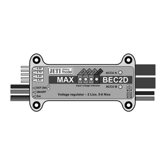
INSTRUCTION MANUAL 2. Description 2.1 MAXBEC2D The supply batteries are connected to the MAXBEC2D via the two pairs of 1.5mm2 wires. These wires do not have a plug fitted. The stabilized output power is delivered via one pair of 1.5mm2 wires with an MPX type plug already fitted for your convenience. The output voltage may be adjusted by using the jumper next to the output wires. -
Page 5: Circuits
INSTRUCTION MANUAL 3. Circuits 3.1 Powering the MAXBEC2D The MAXBEC2D can be powered by up to two batteries. These can vary by cell-count and chemistry and the MAXBEC2D will always take power from the battery with the highest voltage. If both batteries have the same voltage, then the MAXBEC2D will take power from both batteries together. -
Page 6: Connecting The Maxbec2D To A Duplex Receiver
INSTRUCTION MANUAL Batt. A JETIBOX EXT. MAXBEC2D POWER Batt. B UOUT OUTPUT MAGNETIC SWITCH 3.2.2 Connecting the MAXBEC2D to a DUPLEX receiver Connect the MAXBEC2D to the receiver using the red JR connector from the MAXBEC2D. Plug this into the socket marked 'Ext.' on the Duplex receiver. Connect the supply battery to the MAXBEC2D, not forgetting to connect the power output of the MAXBEC2D to your receiver! Now the JETIBOX can be connected to your transmitter module for programming and monitoring of the system. -
Page 7: Menu Navigation
INSTRUCTION MANUAL 4. Menu navigation For parameter setting and monitoring of the MAXBEC2D, the JETIBOX is used. After connecting the JETIBOX according to the above instructions, the screen shows the identification of the unit, the temperature and the voltage of each supply battery. The active power-supply input is marked by a "*" character. -
Page 8: Alarms
INSTRUCTION MANUAL pushing 'R' (Right), the MAXBEC2D output voltage can be set directly from the JETIBOX, overriding the physical position of the Jumper. Beep Volt. Alarm – Set the letter of the alphabet to be acoustically signaled from the transmitter module when the input voltage falls below that specified by “ALARMS->Voltage Alarm”. -
Page 9: Output Voltage Adjustment
INSTRUCTION MANUAL Factory Defaults – by simultaneous pressing of arrows R and L (right and left) the factory settings of the MAXBEC2D are loaded. MBEC2D v. xx.xx ID xxxxx:xxxxx – product marking with firmware version and series number (ID). 5. Output Voltage Adjustment The output voltage of the MAXBEC2D can be adjusted in two ways: ... -
Page 10: Installation
INSTRUCTION MANUAL The switch is designed to be mounted on the fuselage of your model. When the key is offered to the switch, the green LED will flash and after approximately 1 second, the LED will be continuously lit, indicating that the MAXBEC2D is now active. For de-activating the MAXBEC2D, the same principles apply. -
Page 11: Technical Specification Of The Maxbec2D
INSTRUCTION MANUAL 1. Keep the magnet a safe distance from all devices that could be damaged by magnetic interference: Televisions, Credit Cards, PC's and Pacemakers! 2. Keep magnets away from children, due to the risk of ingestion or injury! 10. Technical Specification of the MAXBEC2D Technical data: MAXBEC2D Recommended input voltage 5.5 –... -
Page 12: Menu Diagram Of Maxbec2D
INSTRUCTION MANUAL 12. Menu Diagram of MAXBEC2D -12-...
Need help?
Do you have a question about the PSYCHO4 and is the answer not in the manual?
Questions and answers