Aerogen PRO System Instruction Manual
Hide thumbs
Also See for PRO:
- System instruction manual (42 pages) ,
- System instruction manual (44 pages)
Table of Contents
Advertisement
Advertisement
Table of Contents

Related Manuals for Aerogen PRO


Summary of Contents for Aerogen PRO
- Page 1 System Instruction Manual www.aerogen.com...
-
Page 3: Table Of Contents
Assembly & Installation Installation For Use With A Ventilator Nebulisation Installation For Use Off-Ventilator Functional Test Cleaning, Disinfection and Sterilisation Troubleshooting Warranty Life Of Product Specifications Performance Symbols Appendix 1 Appendix 1: EMC Tables Aerogen Pro System Instruction Manual ®... -
Page 4: Introduction
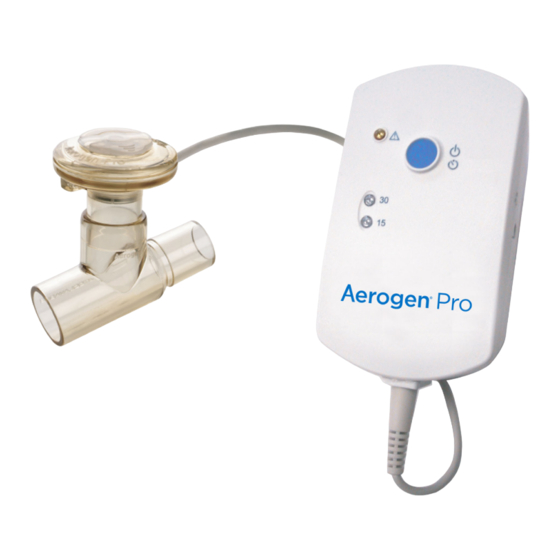
® generator. Aerogen Pro is intended for hospital use only. It is designed to operate in- ® line with standard ventilator circuits and mechanical ventilators. It operates without changing patient ventilator parameters and can be refilled without interrupting ventilation. - Page 5 Aerogen Pro System The Aerogen Pro System includes the following components: Figure 1. Aerogen Pro System 1. Nebuliser with Filler Cap 2. T-Piece (Adult) with Plug 3. Aerogen Pro Controller 4. Controller Cable 5. AC/DC Adapter 6. Universal Mounting Bracket & Equipment Mount Adapter Note: Visit www.aerogen.com for full parts list.
- Page 6 When the nebuliser is connected into the breathing circuit, the filler cap can be opened or removed from the nebuliser without causing loss of circuit pressure. Within the nebuliser is the Aerogen Vibronic aerosol generator, which ® consists of a domed aperture plate with precision-formed holes that control the size of the aerosol droplets and a vibrational element that creates micro-pumping action to aerosolise medication.
-
Page 7: System Warnings
System Warnings Read and study all instructions before using the Aerogen Pro System and accessories. Only trained medical personnel should operate the device. During use observe for correct functioning of the nebuliser by regularly verifying aerosol is visible and no flashing indicator lights. - Page 8 Do not use in the presence of devices generating high electromagnetic fields such as magnetic resonance imaging (MRI) equipment. The Aerogen Pro controller contains a nickel metal hydride (NiMH) rechargeable battery, which should be disposed of in accordance with local governing restrictions at the end of its useful life.
- Page 9 • 30 Min. - Press & hold for 3 Sec. Error Indicator 30 Minute Mode Indicator light 15 Minute Mode Indicator light Battery Status Indicator 9V DC Input Controller Cable Input Figure 2. Aerogen Pro Controls & Indicators Aerogen Pro System Instruction Manual ®...
- Page 10 Table 1. Aerogen Pro Controls & Indicators Control / Indicator Function • Green (steadily lit) = 15 Minute nebulisation cycle on • Green (flashing) = Low battery 15 Min. Indicator power • Nebuliser automatically powers off after 15 minutes have elapsed •...
-
Page 11: Assembly & Installation
Cleaning, Disinfection and Sterilisation section of this manual. Note: The nebuliser and T-piece, as packaged, are not sterile. Perform a functional test of Aerogen Pro before use and between patients as described in the Functional Test section of this manual (see page 19). - Page 12 Connect the Aerogen Pro controller and the nebuliser together using the controller cable (Figure 4). Figure 4. Connecting controller and nebuliser To operate on AC power (the primary mode of operation), connect the Aerogen Pro AC/DC adapter to the Aerogen Pro controller and plug the adapter into an AC power source (Figure 5).
- Page 13 Note: Allow a minimum of four hours for the internal battery to fully recharge. Note: To ensure uninterrupted operation of the Aerogen Pro, secure both the AC/DC adapter cable and the controller cable so they cannot become disconnected during treatment. If clips are available on patient circuits, run the cables through the eyes of the clips.
-
Page 14: Installation For Use With A Ventilator
Y (Figure 6). Figure 6. Connecting the Aerogen Pro to an adult breathing circuit Note: Figure 6 shows adult configuration only 2. For paediatric breathing circuits, connect the nebuliser with the paediatric T-piece into the inspiratory limb of the breathing circuit before the patient Y (Figure 7). - Page 15 (Figure 9). Do not over-tighten knob. Where a standard equipment mount is available, use the equipment mount adapter to support the controller (Figure 9). Aerogen Pro System Instruction Manual ®...
- Page 16 Equipment Universal Mounting Bracket Universal Mounting Bracket Mount Adapter Figure 9. Aerogen Pro controller and universal mounting bracket configurations Warnings • Always maintain the nebuliser in a vertical orientation (with the filler cap uppermost) while in the patient circuit (Figures 6, 7, & 8). This orientation prevents condensate from blocking the nebuliser and ensures proper nebulisation.
- Page 17 Max. fill indication point Figure 10. Filling the nebuliser with a pre-filled ampoule Note: Medication can be added in this manner during nebulisation. This does not interrupt nebulisation or ventilation. Aerogen Pro System Instruction Manual ®...
-
Page 18: Nebulisation
3. To stop the nebuliser at any time, press the On/Off power button. The indicator turns off to indicate that nebulisation has stopped. Note: When delivering a dose greater than 3 mL, select the 30 Minute cycle. Aerogen ®... -
Page 19: Installation For Use Off-Ventilator
Warning: To ensure correct nebulisation, maintain the nebuliser in a vertical orientation (Figure 11). Use with a Mouthpiece The Aerogen Pro works with any standard ISO 22 mm nebuliser mouthpiece inserted into the adult T-piece. Figure 12. Connecting to a mouthpiece... - Page 20 When using a mouthpiece, connect the nebuliser to the T-piece as shown in Figure 3 and then connect the T-piece to the mouthpiece by pushing the parts firmly together (Figure 12). Warning: To ensure correct nebulisation, maintain the nebuliser in a vertical orientation (Figure 12). Aerogen ®...
-
Page 21: Functional Test
Functional Test Perform a functional test of the Aerogen Pro System prior to first use, after each sterilisation before each patient use or at any time to verify proper operation. Follow these steps: 1. Visually inspect each part of the system for cracks or damage and replace if any defects are visible. -
Page 22: Cleaning, Disinfection And Sterilisation
Cleaning, Disinfection and Sterilisation This section describes how to clean, disinfect, sterilise and inspect Aerogen Pro System components. It is important that Aerogen Pro device components are cleaned and sterilised prior to first patient use. The components are: • Aerogen Pro (including filler cap) •... - Page 23 2. Completely immerse parts in appropriate disinfecting agent in accordance with current hospital protocols and disinfectant agent manufacturer guidelines. Note: Aerogen approves the following disinfection solutions for use with its Aerogen Pro nebulisation system regarding material compatibility. With respect to microbiological effectiveness, please ask the manufacturer.
- Page 24 Automated Washing Cycle The Aerogen Pro nebuliser system has been qualified for the following automated washing cycles. Automated Cycle One Detergent: Liquid alkaline cleaner (diluted as per manufacturers instruction). Water Quality: Mains water. Method: 1. Load the components in the automated washer.
- Page 25 Sterilisation of the Aerogen Pro Nebuliser Sterilisation of Aerogen Pro Nebuliser, T-Pieces & Neonate Adapters 1. Disconnect the nebuliser from the controller, and then remove the nebuliser and adapters from the ventilator circuit, mask or mouthpiece. 2. Disassemble the nebuliser and adapters into individual components.
- Page 26 ® 100S Sterilisation System for specific instructions regarding its correct operation. Prior to next use: 1. Check for cracks or damage and replace if any defects are visible. 2. Perform a functional test as described in this manual. Aerogen ®...
- Page 27 • Do not spray liquid directly onto the controller. • Do not immerse controller in liquid. Note: The Aerogen Pro nebuliser contains active electronic components. Aerogen has validated the methods of cleaning, disinfection and sterilisation above. The use of any other means of cleaning, disinfection or sterilisation has not been validated and is likely to reduce the life of your nebuliser and will invalidate your warranty.
-
Page 28: Troubleshooting
Troubleshooting If these suggestions do not correct the problem, discontinue use of any device and contact your local Aerogen sales representative. Table 2. Aerogen Pro Troubleshooting If this happens: It could mean: Try this: The 15 Min. or 30 Min. - Page 29 It may be time to replace Product. Refer to Aerogen the nebuliser. Pro parts list by visiting www.aerogen.com. Note: The rechargeable battery in the Aerogen Pro controller should only be replaced by Aerogen authorised personnel: contact your Aerogen sales representative. Aerogen Pro System Instruction Manual...
-
Page 30: Warranty
As with all active electronic components, the Aerogen Pro nebuliser has a defined life. In the case of Aerogen Pro controller, the life of the controller unit has been validated for use for 1460 doses. This is based on a typical product usage profile over a two year period, including four treatments per day, 50% of the time. -
Page 31: Specifications
Can operate from AC/DC Adapter (input 100 to 240 VAC 50 – 60 Hz, output 9 V) or internal rechargeable battery (4.8 V nominal output). Power Source Note: The Aerogen Pro controller is approved for use with Aerogen AC/DC adapter AG-AP1040-XX* (Manufacturer Reference: FRIWO FW8000M/09 / FW7660M/09) Power Consumption ≤... -
Page 32: Performance
Performance Table 6. Performance Specifications of the Aerogen Pro Flow Rate > 0.2 mL/min (Average ~ 0.4 mL/min) As measured with the Andersen Cascade Impactor: Specification Range: 1-5 μm Average Tested: 3.1 μm As measured with the Marple 298 Cascade Impactor: Specification Range: 1.5-6.2 μm... -
Page 33: Symbols
Symbols Table 7. Aerogen Pro System Symbols Symbol Meaning Symbol Meaning Serial number designation, where Transient storage YY is the year of temperature limitations YYXXXXX manufacture and -20 ºC to +60 ºC XXXXX is the serial number Caution Quantity Attention: Consult... - Page 34 Aerogen Pro nebuliser system. • Do not use the Aerogen Pro adjacent to or stacked with other equipment. If adjacent or stacked use is necessary, the device should be observed to verify normal operation in this configuration.
- Page 35 • Portable and mobile radio frequency (“RF”) communication devices can disrupt medical electrical equipment. * Consult your local representative for the order number extension specific to your country and for pricing information. Aerogen Pro System Instruction Manual ®...
-
Page 36: Appendix 1: Emc Tables
Guidance and manufacturer’s declaration – electromagnetic emissions The Aerogen Pro nebuliser system is intended for use in the electromagnetic environment specified below. The customer or the user of the Aerogen Pro nebuliser system should assure that it is used in such an environment. - Page 37 This Aerogen Pro nebuliser system is intended for use in an electromagnetic environment specified in Table 8. The customer or the user of the Aerogen Pro nebuliser system can help prevent electromagnetic interference by maintaining a minimum distance between portable and mobile RF communications equipment (transmitters) and the Aerogen Pro nebuliser system as recommended below, according to the maximum output power of the communications equipment.
- Page 38 Aerogen Pro nebuliser system that is not life supporting This Aerogen Pro nebuliser system is intended for use in the electromagnetic environment specified below. The customer or the user of the Aerogen Pro nebuliser system should assure that it is used in such an environment.
- Page 39 Table 10. Guidance and manufacturer’s declaration – electromagnetic immunity for the Aerogen Pro nebuliser system that is not life supporting (Continued) Power 30 A/m 30 A/m Power frequency magnetic frequency fields should be at levels (50/60 Hz) characteristic of a typical...
- Page 40 Aerogen Pro nebuliser system that is not life supporting This Aerogen Pro nebuliser system is intended for use in the electromagnetic environment specified below. The customer or the user of the Aerogen Pro nebuliser system should assure that it is used in such an environment.
- Page 41 Table 11. Guidance and manufacturer’s declaration - electromagnetic immunity for the Aerogen Pro nebuliser system that is not life supporting (Continued) IEC 60601 Test Compliance Electromagnetic Immunity Test Level Level Environment - Guidance Radiated RF 10 V/m 10 V/m d = [1.17] √P... 80MHz to 800MHz IEC 61000-4-3 80 MHz to 2.7 GHz...
- Page 42 RF transmitters, an electromagnetic site survey should be considered. If the measured field strength in the location in which the Aerogen Pro nebuliser system is used exceeds the applicable RF compliance level above, the Aerogen Pro nebuliser system should be observed to verify normal operation.
- Page 44 +353 91 540 400 INTL. info@aerogen.com www.aerogen.com twitter.com/aerogen Manufacturer Aerogen Ltd. © 2018 Aerogen Ltd. Galway Business Park, Part No. AG-AP1080-UK Dangan, Galway, P/N 30-012 Rev R Ireland.
Need help?
Do you have a question about the PRO and is the answer not in the manual?
Questions and answers