Advertisement
Link Controls
Stuart Road,
Manor Park,
Runcorn,
Cheshire,
WA7 1TS
T: +44 (0)1928 579050
F: +44 (0)1928 579259
www.linkcontrols.co.uk
enquiries@linkcontrols.co.uk
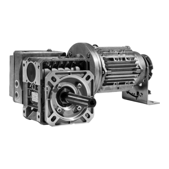
Instructions for Rolling Door Operator type :
CDO
Warning : Please read these instructions fully before installation
Door Operator / CDO/ LC-3158 Rev.B
Advertisement
Table of Contents

Related Manuals for Link Controls CDO Series

Summary of Contents for Link Controls CDO Series
- Page 1 Link Controls Stuart Road, Manor Park, Runcorn, Cheshire, WA7 1TS T: +44 (0)1928 579050 F: +44 (0)1928 579259 www.linkcontrols.co.uk enquiries@linkcontrols.co.uk Instructions for Rolling Door Operator type : Warning : Please read these instructions fully before installation Door Operator / CDO/ LC-3158 Rev.B...
-
Page 2: Table Of Contents
Overview of products operating instructions are adhered to. Installation Link Controls is not liable for any personal injury or damage Initial Operation to property that occurs as a result of the warning and safety Emergency operation instructions being disregarded. -
Page 3: Overview Of Products
Overview of products Regulations and bases for testing Various options For connecting, programming and servicing, the following The following package options are available for the regulations must be observed (the list is not exhaustive). flange mounted CDO Rolling Door operator: Construction product standards The operators listed below can be supplied with - EN 13241-1 (Products without fire resistance or smoke... -
Page 4: Installation
Installation Preparation CDO Operator - Flange Mount Handing Handing the operator Danger! The CDO Range of operators can be supplied for To avoid injury, the following points must left or right hand installation. Please refer to the be observed: diagram below when ordering. - The operator must be installed free of any tension. - Page 5 Information: Link Controls Ltd. constantly strives to improve the quality of its goods and as such reserves the right to replace/modify products without prior notification. Any examples given are intended for guidance only.
-
Page 6: Initial Operation
Installation Initial Operation Installation of the emergency hand chain Motor Connections (for operators with emergency hand chain) ‘Standard’ 3ph Motor Connection Information: To ensure that they work correctly, the chain links must not be twisted. 3 x 400V Star connection (standard) The motor should be configured as shown above for connection to a 3 x 400V control panel. - Page 7 ‘Inverter Drive’ 3ph Motor Connection Mechanical Limit Switches Terminals Control / Limit Cams Worm Gear 3 x 230V Delta connection (inverter) The motor should be configured as shown above for connection to a 3 x 230V control panel. Control cam for limit switch, CLOSED (green) Warning! Control cam for limit switch, OPEN (white) Control cam for limit switch, AUX (yellow)
- Page 8 Setting Mechanical Limits Check the system Control / Limit Cam Adjustment Check the direction of travel Drive the door in the CLOSED direction. ☞ The operator must close the door. Drive the door in the OPEN direction. ☞ The operator must open the door. Locking Screw Fine Adjustment Screw Information:...
- Page 9 6.6 Digital Limits Wiring allocation, Electronic interface AVE (absolute value encoder) plug The numbers on the plug are also the wire numbers. Safety circuit input (N/C) AVE plug (absolute value encoder plug) RS 485 B AVE plug terminal (absolute value encoder plug terminals.
-
Page 10: Emergency Operation
Emergency Operation Operation with emergency wheel Danger! guide & interlock To avoid injury, the following points must be observed: - Emergency operation may only be carried out from a safe standing position. - Emergency operation may only be carried out when the motor is stationary. - The system must be disconnected from the power supply during emergency operation. -
Page 11: Maintenance
Maintenance Operation with emergency floor level hand chain (KE) Warning! To avoid damage to the operator and door, the following points must be observed: - Maintenance must only be carried out by authorized persons. - Directive BGR 232 must be complied with. - Worn or faulty parts must be replaced. -
Page 12: Eu Declaration Of Conformity
Machinery Directive 2006/42/EC. Place / Date: Runcorn, 20/04/2016 Manufacturer’s signature: Certificate Number 10668 ISO 9001 Link Controls Ltd. reserves the right to change / modify products without prior notification 12 – Door Operator / CDO / LC- 3158 Rev.B 02/01/2018...
Need help?
Do you have a question about the CDO Series and is the answer not in the manual?
Questions and answers