
Related Manuals for ARRI ALEXA Mini LF


Summary of Contents for ARRI ALEXA Mini LF
- Page 1 ALEXA Mini LF ALEXA Mini LF Software Update Package 6.0 Software Update Package 6.0 U S E R U S E R M A N U A L M A N U A L September 10, 2019 September 10, 2019...
- Page 2 GmbH & Co. Betriebs KG. Specifications are subject to change without notice. Errors, omissions, and modifications excepted. AMIRA, ALEXA, ALEXA XT, ALEXA SXT, ALEXA LF, ALEXA Mini and ALEXA Mini LF are trademarks or registered trademarks of Arnold & Richter Cine Technik GmbH & Co. Betriebs KG. All other brands or products are trademarks or registered trademarks of their respective holders and should be treated as such.
-
Page 3: Table Of Contents
Safety Guidelines......................10 Sensor Related Information / 有关影像传感器的信息 ............12 Audience and Intended Use..................14 Scope of Delivery and Warranty................... 15 Introduction to the ALEXA Mini LF................16 Camera Layout........................ 17 Camera Rear Connectors....................19 Camera Left and Front Connectors................21 Media Bay........................22 Product Identification...................... - Page 4 Contents Main Parameters......................51 14.1 Project Settings.......................51 14.2 Sensor Frame Rate......................52 14.3 Shutter..........................53 14.4 Exposure Index....................... 53 14.5 ND Filter..........................54 14.6 White Balance.........................55 14.7 Timecode.........................56 Look Settings........................59 15.1 Processing and Color Spaces..................61 Recording.........................63 16.1 Recording Media Handling..................... 63 16.1.1 Erase of Recording Media....................64 16.1.2...
- Page 5 Contents Synchronization......................90 19.1 EXT Sync........................90 19.2 Genlock Synchronization....................93 19.3 Timecode Synchronization....................93 Sensor Settings.......................94 20.1 Noise Reduction......................94 20.2 Mirroring the Sensor Image....................94 20.3 User Pixel Masking......................95 System Settings......................97 21.1 Language Setting......................97 21.2 System Time and Date....................97 21.3 Button and Display Settings...................
- Page 6 Contents Transvideo Starlite HD5-ARRI Monitor............... 119 Appendix........................121 28.1 Companion Tools......................121 28.2 Connector Pin-Outs...................... 124 28.3 Technical Data......................127 28.4 Declarations of Conformity................... 130 28.5 Dimensional Drawings....................134...
-
Page 7: Disclaimer
In no event shall ARRI or its subsidiaries be liable for or have a remedy for recovery of any special, direct, indirect, incidental, or consequential damages, including, but not limited to lost profits, lost savings, lost... -
Page 8: For Your Safety / 为了您的安全
For Your Safety / 为了您的安全 For Your Safety / 为了您的安全 Before use, please ensure that all users read, understand and follow the instructions in this document fully. 使用前,请确保所有的用户都已经阅读、理解,并遵循本文档内的操作说明。 Risk Levels and Alert Symbols / 危险级别和警示标志 Safety warnings, safety alert symbols, and signal words in these instructions indicate different risk levels: 本文档内的安全警告、安全警示标志和标识词语指示不同的危险级别:... -
Page 9: Vital Precautions / 重要安全措施
Always unplug the power cable by gripping the power plug, not the cable. Never try to repair. All repair work should be done by a qualified ARRI Service Center. Never remove or deactivate any safety equipment (incl. warning stickers or paint-marked screws). -
Page 10: Safety Guidelines
► Heed all warnings on the system and in the safety and operating instructions before you operate or install the system. Follow all installation and operating instructions. ► Do not use accessories or attachments that are not recommended by ARRI, as they may cause hazards and invalidate the warranty. - Page 11 If the contamination cannot be removed, the camera should be taken to an ARRI service center for cleaning. ► Clean optical lens surfaces only with a lens brush or a clean lens cloth. In cases of solid dirt or grease, moisten a lens cloth with pure alcohol.
-
Page 12: Sensor Related Information / 有关影像传感器的信息
Sensor Related Information / 有关影像传感器的信息 Sensor Related Information / 有关影像传感器的信息 Single Frame Spots of Various Shape – also known as “Digital Dust” or “White Flecks” Natural and/or artificial radiation may cause a “false exposure” on the image sensor. The shape of these spots may vary from dots to lines or other, sometimes irregular shapes. - Page 13 曝光时间越长,这些像素会变得越多。当曝光时间长于 1/24 秒时,请仔细检查画面是否符合您的要求。 Stitching with ALEXA Mini LF The ALEXA Mini LF sensor consists of a large sensor structure that is created by exposing two Super 35 sensor structures side by side onto a silicon wafer. This process is, somewhat misleadingly, called “stitching”.
-
Page 14: Audience And Intended Use
Audience and Intended Use Audience and Intended Use The ALEXA Mini LF is a large format digital camera solely and exclusively for recording images at various resolutions suitable for a variety of distribution formats: Apple ProRes 422 HQ, Apple ProRes 4444, Apple ProRes 4444 XQ and ARRIRAW codec... -
Page 15: Scope Of Delivery And Warranty
ARRI offers an increasing variety of product bundles and additional accessories. For details, please consult our website or your local ARRI Service Partner. Warranty For scope of warranty, please ask your local ARRI Service Partner. ARRI is not liable for consequences from inadequate shipment, improper use or third-party products. -
Page 16: Introduction To The Alexa Mini Lf
ProRes and uncompressed ARRIRAW up to 60 fps, provide unprecedented creative freedom. ALEXA LF and ALEXA Mini LF have the biggest sensor area of any cinema camera on the market, second only to ARRI Rental’s ALEXA 65. Maintaining the ALEXA family’s optimal pixel size for highest overall image quality results in a 4448 x 3096 picture, which can be recorded in full using the LF Open Gate recording resolution. -
Page 17: Camera Layout
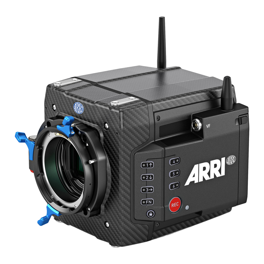
Camera Layout Camera Layout Camera Right Rear Connectors Radio Antenna Connector Fan Intake Sensor Plane Marking LBUS Connector (on Lens Mount) Integrated WiFi Antenna Camera Left Record Button Camera Buttons VF Viewfinder Connector WiFi Antenna Connector Media Door Release Camera Status LED Camera Front LPL Lens Mount LBUS Connector (on Lens Mount) - Page 18 Camera Layout Camera Rear Boot Status LED POWER Button Camera Status LED Media Door Media Status LED Window WiFi Antenna Connector Fan Outlet White Radio Antenna Connector Rear Connectors Camera Top WiFi Antenna Connector VF Viewfinder Connector Attachment Points for Mechanical Acces- sories Camera Bottom LBUS Connector (on Lens Mount)
-
Page 19: Camera Rear Connectors
The audio connector is a 2-channel +24 dBu line level audio input with an additional regulated 12 V power output with a current of 0.5 A. Use the ALEXA Mini LF Audio connector with cable (K2.0023988) to connect audio sources. - Page 20 Tri-Level HD signals. BAT (8-pin LEMO) The BAT connector is the main power input of the ALEXA Mini LF and accepts an input voltage range from 11.0 to 34.0 V DC. You can use power cables KC50-S (K2.75007.0) or KC50-SP-S (K2.0001275) or one of the various on-board adapter plates for V-Mount and Gold Mount batteries to supply the camera with power.
-
Page 21: Camera Left And Front Connectors
WiFi Antenna Connector (RP-SMA) Besides the built-in WiFi antenna behind the camera label on the right side, the ALEXA MINI LF is equipped with a second WiFi antenna connector above the media bay on the camera left side. Both internal and external WiFi antenna work together, and if needed, the external antenna output can be disabled in the camera menu. -
Page 22: Media Bay
Recording Media Slot The ALEXA Mini LF records clips onto Codex Compact Drives, using the media bay on the camera left side. A small window (3) in the media bay door shows the LED of the Compact Drive. To access the media slot, slide the media bay door release (2) towards the camera back so that the spring-loaded door jumps open. -
Page 23: Camera Support
(K2.0014957, K2.0023546) ALEXA Mini, and also ALEXA Mini LF on camera right. The MSB-3 is a side bracket designed around the media bay of the ALEXA Mini LF and the new viewfinder connector on the camera left. Center Camera Handle CCH-2... - Page 24 Camera Support Mounting MAP-2A, BPA-4 and BP-8 ► Using a 3.0 mm Allen key, fasten the Mini Adapter Plate MAP-2 or MAP-2A (1) to the camera top attachment points with the four 3.0 mm hex screws. Tighten them cross- wise. ►...
- Page 25 Camera Support Mounting MSBs, CCH-2 and MVB-1 ► Using a 3.0 mm Allen key, fasten the Mini Side Bracket MSB-3 (1) to the camera's left side. The MSB-3 is attached with two 3.0 mm hex screws each to the dedicated mounting points of the top and the bottom Mini Adapter Plates MAP-2A.
-
Page 26: Power Supply
Power Supply BAT IN The ALEXA Mini LF accepts an input voltage range from 11.0 to 34.0 V DC. The camera can be solely powered through the 8-pin LEMO BAT connec- tor located at the back of the camera. You can use the KC50-S (K2.75007.0) or KC50-SP-S (K2.0001275) power cable or one of the various on-board... - Page 27 As soon as the camera has finished the boot process, the boot status LED turns to solid blue. During the boot process, the ARRI logo is shown in the flip-out monitor of the MVF-2 (if connected). Switching Off the Camera ►...
-
Page 28: Lens Mounts And Lens Handling
Lens Mounts and Lens Handling Lens Mounts and Lens Handling The ALEXA Mini LF is equipped with a universal lens mount base for interchangeable lens mounts allowing the use of various lenses. ARRI Large-format Lenses Signature Prime Lenses ARRI Rental DNA LF and 65 Format Lenses... -
Page 29: Changing A Lens
Any LDS-2 mount and any LDS-2 lens always have the contacts in the 12:00 position. The description below shows the ALEXA Mini LF with an LPL mount attached. When no lens is attached to the camera, use the lens port cap to prevent dust from entering the lens cavity. - Page 30 Lens Mounts and Lens Handling Attaching a Lens 1. Carefully insert the lens into the lens port. Align the notch in the lens flange (1) with the index pin on the lens mount (2), keeping the lens rotated into a position where the lens markings are visible from either side of the camera.
-
Page 31: Maximum Lens Mounting Depth
Changing the Lens Mount The ALEXA Mini LF is equipped with a universal lens mount base that uses the same camera to lens mount interface as used on the ALEXA Mini and AMIRA, so all lens mounts that fit on ALEXA Mini and AMIRA will physically also fit on the ALEXA Mini LF. - Page 32 After each lens mount change, always check the flange focal depth of the camera. Have the flange focal depth always corrected by properly skilled personnel. Flange focal depth correction requires special tools and training that meet ARRI guidelines. For all flange focal depth issues, contact a qualified ARRI Service Center.
-
Page 33: Lens Data
SDI stream. LDS-2 is the next evolution of ARRI’s Lens Data System for ARRI's Electronic Control System and a new generation of lenses. LDS-2 delivers more accurate and faster lens data. Compared to LDS-1 it eliminates the need for initial calibration through absolute encoders which cuts time on set when changing lenses. - Page 34 Lens Mounts and Lens Handling ARRI Lens Data Archive (LDA) Lenses without LDS can be integrated into the system via the Lens Data Archive (LDA). By mapping a lens, all information about the lens, its scales, name, and serial number can be transferred into a lens archive.
-
Page 35: Multi Viewfinder Mvf-2
Multi Viewfinder MVF-2 Multi Viewfinder MVF-2 Flip-out Monitor Diopter Adjustment Proximity Sensor ZOOM Button EXP Button PLAY Button VF 1&2 User Buttons Top Tally Light SET Button User Wheel LOCK Switch REC Button Dove Tail Service Cover Bottom Tally Light Product Label Viewfinder Connector Headphones Out... - Page 36 K1.0024074 - XXXXX. Viewfinder Connector The ALEXA Mini LF uses an industrial CoaXPress interface to connect the MVF-2 viewfinder with the camera. The interface transmits power, video and control data and supports cable lengths of up to 10 m (33 ft).
-
Page 37: Flip-Out Monitor
Multi Viewfinder MVF-2 Headphones Out The headphones out (18) is a 3.5 mm TRS connector (headphone jack), which outputs all four audio channels with a maximum power of 2.5 dBm. NOTICE Constantly covering the proximity sensor of the MVF-2 can cause an irreversible burn-in on the viewfinder OLED display. -
Page 38: Cables
Multi Viewfinder MVF-2 JOGWHEEL The JOGWHEEL (1) is used to ► scroll or navigate through lists and menus ► change values (by scrolling up or down) ► access and confirm settings (by pressing the JOGWHEEL center) HOME / LIVE Button The HOME / LIVE button (2) toggles to display either the HOME screen (shown in the image above) or the camera live view. -
Page 39: Menu Operation
To access the menu, press the MENU / BACK button on the MVF-2 or connect to the camera via WiFi or Ethernet and open the "web remote", page 117. The ALEXA Mini LF menu consists of 11 submenus: Recording... -
Page 40: Home Screen
This is the color temperature of the light source that the camera is currently adjusted for. In addition to the red/blue correction of the white balance, the ALEXA Mini LF can also compensate for a green/magenta tint. This value, called CC (color compensation), is shown as an exponent of the WB... - Page 41 Menu Operation White balance can be adjusted from 2,000 to 11,000 Kelvin (here: 5,600) in steps of 10 K for red/blue correction. Color compensation for green/magenta tints can be adjusted in a range from -16.0 to +16.0. Positive or negative CC color compensation values then appear as an exponent of the WB value (here: +0.0).
- Page 42 Menu Operation Media Capacity & Look Settings Remaining capacity of the recording media, at current FPS and codec combination, in MEDIA real time. When media capacity is below 2 minutes, capacity values start flashing. Active recording processing (ARRIRAW or Log C) LOOK Active Look Status Icons...
-
Page 43: Using The On-Screen Keyboard
Menu Operation Audio Icon. Internal microphones are enabled. MVF-2 eyepiece heater is active. Black Eyepiece heater is active. Gray Eyepiece heater is not heating (eyepiece temperature is > 15 °C (59 ° F)). Genlock Icon Black Camera is synchronized to genlock source. Orange Camera is not synchronized to genlock source (signal not present or unusable). -
Page 44: Working With Lists And Import Of Files
Menu Operation 13.3 Working with Lists and Import of Files For certain parameters, the camera menu operates with lists that come with a default content and that can be adjusted to the user's preference. You can ADD values to and DELETE values from these lists, so that only project relevant values are displayed. - Page 45 "User Storage Handling", page 47 for more information. Files are imported from these USB folders: File Type Corresponding USB Folder Look Files ARRI/A-MINI-LF/LOOKFILES Frame Lines ARRI/A-MINI-LF/FRAMELINES User Setups ARRI/A-MINI-LF/SETUPS...
-
Page 46: Function Button Fn
Menu Operation 13.4 Function Button FN The camera's left side is equipped with the function button FN (1) and six camera buttons of which four are labelled with additional icons (2). These four buttons can act as regular user buttons or in combination with the FN button access common camera functions. -
Page 47: User Storage Handling
User Storage Handling The ALEXA Mini LF saves data such as user setups, frame grabs and system logs to a USB memory stick. Firmware, additional frame lines and ARRI Look File 2 files can be loaded onto the camera using the USB memory stick. -
Page 48: Info Screens
Menu Operation 13.6 Info Screens The INFO screens provide detailed information about the current state of the camera system. ► Select MENU > Info. The INFO list contains the following entries. Version Info Lens Info System Info User Button Info Maximum FPS Info EXT Sync Info Media Info... - Page 49 Export HW Info File HW (HardWare) info files are required to generate licenses in the ARRI License Shop or may be requested by camera service to get detailed information on the camera's hardware and components. The HW Info file will be exported to the USB medium in the ARRI/A-MINI-LF/LICENSES folder.
-
Page 50: Alerts Screen
Similar to regular logfiles, update logfiles help camera service to analyze problems that occured during the update process. In normal circumstances, exporting update logfiles is not required. Update logfiles will be exported to the USB medium in the ARRI/A-MINI-LF/LOG folder. 13.7 Alerts Screen Alert messages communicate critical system states to the user. -
Page 51: Main Parameters
The next reel count ets the reel number assigned to the next new media used for internal recording. A new media is either a blank media or a media with reels of other ALEXA Mini LF cameras. The camera automatically advances the reel number every time new media is formatted on the camera. The reel number is reflected in clip names and is displayed on the home screen. -
Page 52: Sensor Frame Rate
Main Parameters Camera Index Color Set the color of the camera index letter displayed in the status info of the SDI outputs (e.g. to match it to the color coding of your cameras). 1. Select MENU > Monitoring > SDI > SDI Processing > Overlays > Status Components > Camera Index Letter to display the camera index letter in the SDI status info. -
Page 53: Shutter
14.4 Exposure Index The Exposure Index (EI) is the applied sensitivity of the camera. The ALEXA Mini LF has a base sensitivity of 800 ASA. This means that the dynamic range is almost evenly distributed above and below neutral gray with low noise in the shadows and clean, smooth clipping behavior in the highlights. -
Page 54: Nd Filter
ND Filter Internal FSND Filters The ALEXA Mini LF has a built-in motorized and sealed filter stage for Full Spectrum Neutral Density filters (FSND) with densities of 0.6, 1.2 and 1.8 (and an optical clear filter). In comparison to IRND filters, which have an uneven spectral behavior, or to an ordinary ND filter, which opens up at about 675 nm, the FSND filters offer a true, even reduction over the whole spectrum. -
Page 55: White Balance
SDI outputs. The camera offers various ways to adjust the ND filter: ND Filter screen Camera user buttons WCU-4 user buttons ARRI Master Grips and Operator Control Unit OCU-1 user buttons Web remote Applications communicating with the camera through the Camera Access Protocol (CAP). Selection in camera menu 1. -
Page 56: Timecode
Main Parameters Automatic White Balance Automatic white balance calculates the white balance based on the camera's live image and overwrites the active white balance value. The result is stored as first entry in the WB list. Automatic white balance can be triggered through a dedicated button in the white balance screen or through a user button assigned with Auto WB. - Page 57 Main Parameters Rec Run Timecode Use: Rec run timecode is often used on single camera productions that are either MOS or use a dumb slate to sync picture and sound. Record run timecode guarantees contin- uous timecode on all recorded data. Record run timecode also works with over- and undercranking.
- Page 58 Main Parameters Depending on the timecode run mode, regen behaves differently: Regen Run mode rec run: The camera determines the timecode of the last frame of the last recorded clip and increments it by one for the next clip. This ensures consecutive timecodes for a sequence of clips.
-
Page 59: Look Settings
After recording, backup and data transfer the look can be extracted from the clip’s file header using the ARRI Color Tool again. This way the look can travel to post production as an ARRI Look File 2 or as a 3D LUT. - Page 60 ARRI Look File 2, as the camera does not take into account which ARRI Look File 2 was active when the clip was recorded. It is the responsibility of the user to make sure the correct ARRI Look File 2 is applied during playback.
-
Page 61: Processing And Color Spaces
Look Select to apply the look set in MENU > Look > Look to the output path. Applies a video display processing to camera images. The default ARRI 709 look complies with the ITU.R-BT709 standard for display on standard broad- cast monitors. - Page 62 Look Settings Material recorded in Rec 709 (short for ITU Recommendation BT.709) has a REC 709 display specific encoding. The purpose of a display specific encoding is to im- mediately provide a visually correct representation of the camera material, when it is screened on a certain display device. This is achieved by mapping the actual contrast range of the scene into the contrast range that a display device can reproduce.
-
Page 63: Recording
Recording Media Handling About Codex Compact Drives Compact Drives have been specifically designed for the small form factor of the ALEXA Mini LF, using new flash technology in a miniaturized casing. The drives offer data rates of up to 8 Gbps and support all image and recording formats of the camera. -
Page 64: Erase Of Recording Media
16.1.1 Erase of Recording Media Before using a Codex Compact Drive with ALEXA Mini LF, you need to erase it in-camera to create the required file system. Capture Drives are initialized with the UDF file system which is read-only for computers. -
Page 65: Remaining Recording Capacity And Media Information
Other Ways to Start Recording The camera offers various other ways to start recording: Through the LBUS connector, using ARRI Master Grips or the Operator Control Unit OCU-1 Through the built-in white radio, using Wireless Compact Unit WCU-4 or Single Axis Unit SXU-1... - Page 66 ARRIRAW frame. This checksum is recorded as part of the image header and can be used by software like ARRI Meta Extract, to verify that the ARRIRAW image content has not changed during any copy step. Note that this checksum does not validate the entire file, only the image data itself.
-
Page 67: Recording Resolution
Recording Recording Codec Color Coding Bit Rate (VBR, 24fps, 3840x2160) MXF/ARRIRAW 12bit log 2389 Mbps 2. Select the desired recording codec. Note: When the recording codec family is changed, the camera has to perform a partial software reload. A popup window shows the settings that are affected by the reload and that may not be available after the change. -
Page 68: Audio Recording
Recording 2. Select the desired recording resolution. Note: Changing between recording resolutions may require a software reload. Confirm the reload before it is performed. A popup window shows the settings that are affected by the reload and which may not be available in the new mode. After confirming the popup, the software is reloaded. 16.5 Audio Recording The camera can record 4 channel linear PCM (24 bit, 48 kHz) audio. - Page 69 Recording A limiter prevents the signal from clipping if the input signal level combined Manual (+L) with the set gain results in signal levels exceeding -6 dBFS. Auto Auto matches a 4 dBu input signal to -20 dBFS. This setting leaves enough headroom for recording and avoids audio clipping.
-
Page 70: Rec Beeper And Tally Settings
16.7 File Naming Scheme The ALEXA Mini LF automatically names files as they are created on the recording media. While it is possible to change the file names later on a computer, it is not recommended, as the ALEXA naming scheme has been developed to minimize the risk of duplicate file names. -
Page 71: Data Handling
Recording 16.8 Data Handling Transferring recorded material from the original media should never be done using a simple file copy. There are different software solutions available that will copy a file to one or several destinations and perform a checksum calculation, comparing the material on the original media to the copies, to provide a minimum effort safety check of data integrity. -
Page 72: Playback
Playback Playback The camera offers various ways to start in-camera playback from the recording medium: ► Using the PLAY button on MVF-2 ► Using user button 3 in combination with the Function Button FN ► Using a user button assigned with playback ►... - Page 73 Playback Cliplist The cliplist lists all clip on the recording medium. For the selected clip, details like resolution, codec, duration and timecode are displayed. When browsing through the cliplist, the first frame of the selected clip is shown on EVF/Monitor and the SDI outputs. 1.
-
Page 74: Monitoring
Monitoring Monitoring The monitoring submenu covers all settings related to EVF, Monitor and SDI as well as frame lines and other overlays on these outputs. 18.1 Status Information and Status Overlays EVF and SDI Status Information The camera displays camera status information on the MVF-2 and the SDI outputs. At the top and bottom of the screen, the camera displays textual status information. - Page 75 Other Center Cross Marks the center of the image to help in framing. Frame Line Frame line (here: ARRI 1:1.85) Shows measurements from Ultra Distance Measures. Focus Shows the current focus distance of the lens (if lens data is available).
- Page 76 Monitoring Configuration of Overlays 1. Select MENU > Monitoring > EVF/Monitor > EVF Overlays. Select MENU > Monitoring > EVF/Monitor > Monitor Overlays. Select MENU > Monitoring > SDI > SDI Processing > SDI Overlays. Following settings are available: Frame Lines Sets frame lines on or off.
-
Page 77: Flip-Out Monitor Status Bar
Monitoring Displays the camera index letter in the top right corner of the image. Camera Index Letter Helps to identify camera image output when shooting with multiple cameras. Note: Only available for SDI. Electronic Horizon Displays an horizon overlay representing the roll and tilt of the cam- era measured by the camera's position sensor. -
Page 78: Surround View
Monitoring Activation and Control Using the Camera Buttons 1. Activate the overlay menu by pressing FN + 1. 2. Select a parameter with buttons 1 or 2. 3. Start editing the parameter by pressing button 3. 4. Select the new parameter value with buttons 1 or 2. 5. -
Page 79: Magnification
Two screen shots from an ALEXA Mini LF in recording resolution LF Open Gate 4.5K with a 1.78 UHD frame line (red rectan- gle) applied. The left screen shot shows the SDI output without magnification applied. The right screen shot shows the SDI out- put with magnification applied to enlarge the image (in this example set to 135%). -
Page 80: Frame Lines
Monitoring 18.4 Frame Lines To aid in framing, both the MVF-2 and the SDI outs can display frame lines overlaid on the image. Frame lines can be considered electronic versions of ground glass markings in film cameras. You can configure which frame line the camera should show and how it should be displayed (color and transparency). -
Page 81: Anamorphic Desqueeze
Monitoring Width Adjusts the user rectangle width in the range of 0-999. Height Adjusts the user rectangle height in the range of 0-999. Offset Left Adjusts the horizontal user rectangle offset in the range of 0-1000. Offset Top Adjusts the vertical user rectangle offset in the range of 0-1000. Reset All Resets all values. -
Page 82: Exposure Tools
Monitoring 2. Enable or disable anamorphic desqueeze for the EVF/Monitor and/or SDI outputs. 3. Additionally you can assign "EVF/Mon. Desqueeze" and "SDI Desqueeze" to user buttons to quickly enable and disable anamorphic desqueeze for the corresponding path. For further information on how to assign functions to user buttons please see "User Buttons", page 107. - Page 83 Monitoring Exposure Color Signal Level White Clipping 100% - 99% Just below white clipping Yellow 99% - 97% One stop over medium gray ( 56% - 52% Pink Caucasian skin 18% medium gray 42% - 38% Green Just above black clipping 4.0% - 2.5% Blue Black clipping...
-
Page 84: Zebra
Monitoring 18.6.2 Zebra In Zebra mode, the camera overlays up to two luminance ranges with diagonal stripes. High zebra ranges above, Mid zebra around the user defined luminance value. Zebra Configuration ► Select MENU > Monitoring > Exposure Tools > Select EVF/Mon. Exp. Tool and select Zebra to use Zebra as exposure tool for EVF and Monitor. -
Page 85: Zoom
Monitoring Adjusts the threshold for Color Peaking to become active, relative to the Peaking Offset Shift peaking level. Note: A negative offset shift, in particular with high ASA ratings, can increase the peaking results. Color Select the color for Color Peaking. Activation of Peaking with User Buttons 1. -
Page 86: Sdi Configuration
Monitoring 3. Assign a user button with SDI Zoom (Smart). The SDI Zoom (Smart) user button activates Zoom on the first button press, further button presses change the zoom position and a button long press deactivates Zoom. 18.8 SDI Configuration SDI Format Both SDI BNC connectors output SDI signals in 1920 x 1080 (422 1.5G, 422 3G, 444 3G) 3840 x 2160 (422 6G) according to SMPTE standards 292M, ST 424:2012 and ST 2081. - Page 87 Monitoring Activates or deactivates surround view. Surround View Magnification Apply magnification to the SDI outputs. Exposure Tool Activates or deactivates the exposure tool. Peaking Configures peaking for SDI. Overlays Configures the SDI overlays. SDI Frame Rate You can set the frame rate together with the scan format on the SDI output. If the frame rate is lower than the sensor fps, frame drops will occur.
-
Page 88: Evf/Monitor Settings
Monitoring If both SDI 1 and 2 are supposed to show processed images, SDI 2 needs to be configured as SDI 1 clone. SDI 2 Clone You can set SDI 2 as a clone of SDI 1. SDI 2 will inherit all settings from SDI 1. The configuration options for SDI 2 are grayed out while it is configured as a clone of SDI 1. -
Page 89: Color Bars
Monitoring Monitor Flip Mode Auto Flips the monitor image automatically depending on the monitor's orientation. This is the default setting. Normal Ignores the monitor's orientation sensor and displays the monitor image in normal orientation. Flipped Ignores the monitor's orientation sensor and displays the monitor image in flipped orientation (upside down). -
Page 90: Synchronization
19.1 EXT Sync Up to 16 ALEXA Mini LF cameras can be synchronized for various applications requiring sensor synchronization. One camera is set as the master camera and the other cameras function as slave cameras. Cameras can be connected to each other via the EXT connector, using the MINI-EXT-sync cable (K2.0009051) and the EXT Distribution Box EDB-2 (K2.0013145). - Page 91 Synchronization EXT Sync Mode One camera is functioning as the master camera and the other camera(s) as slave camera(s). A slave camera can be a sensor slave (only sensor synchronized) or a settings slave (sensor and settings synchronized). 1. Connect the cameras via their EXT connector using the MINI-EXT-sync cable(s) and the EXT Distribution Box EDB-2.
- Page 92 Synchronization 3. On the master camera in an EXT sync cluster, you need to define the amount of cameras used in the cluster. The master camera monitors the connection to each slave camera. On the master camera, select MENU > System > Sensor > EXT Sync Camera Count and set the number of cameras used in your cluster (including the master camera, up to 16 cameras).
-
Page 93: Genlock Synchronization
Synchronization A001_CH8B A001_AH8B A001_C001_190705_AH8B A001_C001_190705_CH8B A001_C002_190705_AH8B A001_C002_190705_CH8B A001_C003_190705_AH8B A001_C003_190705_CH8B A001_BH8B A001_DH8B A001_C001_190705_BH8B A001_C001_190705_DH8B A001_C002_190705_BH8B A001_C002_190705_DH8B A001_C003_190705_BH8B A001_C003_190705_DH8B Note: Do not mix sensor and settings slaves as this will cause inconsistencies in clip naming. 19.2 Genlock Synchronization The camera's sensor and SDI outputs can be synchronized to a reference sync signal (a tri-level HD signal or an analog black burst signal) using the SYNC IN BNC connector. -
Page 94: Sensor Settings
ARRI customers like. Using ARRI Noise Reduction ANR-1 enables you to use noise reduction on set in the camera. This can be helpful for low light shots, where an in-camera noise reduction is a very fast solution. Furthermore, ARRI Noise Reduction ANR-1 gives you the possibility to combine the amount of grain with your sharpness and detail settings for the chosen exposure directly on set. -
Page 95: User Pixel Masking
20.3 User Pixel Masking All sensors exhibit a certain number of defect pixels, and ARRI cameras have two mechanisms to catch and correct them: one is a static pixel correction based on a pixel mask created during manufacturing, and the other is a dynamic pixel correction that continuously evaluates each frame and masks defect pixels that are not caught by the static pixel mask. - Page 96 Sensor Settings As an added service, it is possible to send the User Pixel Mask to ARRI Service at service@arri.de for verification. We strongly recommend that you take advantage of this free service, as sometimes, clusters are difficult to spot depending on the background. Please note, however, that in the end, it is the responsibility of the person creating the User Pixel Mask to verify that no clusters are formed.
-
Page 97: System Settings
System Settings System Settings 21.1 Language Setting 1. Select MENU > System > Language. 2. Set the language to either English or Chinese (simplified). 21.2 System Time and Date ► Select MENU > System > System Time + Date to set the system time and date. Note: Timezone and Daylight Saving Time do not change time and date settings. -
Page 98: Lens Mount Settings
WiFi Settings The WiFi module in the ALEXA Mini LF can be configured to act as an access point or in infrastructure (client) mode and opens up a wireless network in the 2.4 GHz band. A WiFi connection can be used to remote control the camera using the camera's web remote or applications communicating with the camera via the Camera Access Protocol (CAP). - Page 99 When using WiFi and White Radio simultaneously it is important to configure the used channels to avoid interference and guarantee optimal performance. The following table gives an overview of suitable channel configurations: ARRI White Radio Channel Number WiFi Channel ZigBee IEEE 802.15.4 Radio Channel Number 2.
- Page 100 System Settings 3. Press CONNECT. The camera connects with the network. The name of the network is displayed in the WiFi NETWORKS AVAILABLE list. Disconnect from Network (Client Mode) 1. Select MENU > System > Network / WiFi > WiFi Network. 2.
-
Page 101: Reset Of Electronic Horizon
The Software Update Package (SUP) can be found in the Software and Firmware Updates for Cameras section on the ARRI website. You need to register your camera, along with your camera serial number, to access the SUP download. Existing ALEXA customers with an active account for the download section can use this account, unless otherwise requested. -
Page 102: Update Of Camera Components
The component is updated. A success message is displayed after the update has finished. 21.9.3 Update of LBUS Devices The camera offers to update connected LBUS devices (cforce mini motors, cforce Plus motors, ARRI Master Grips, ARRI Operator Control Unit OCU-1 and ARRI LCUBE) 1. -
Page 103: User Setups
Loading a User Setup You can load user setups stored on the camera or on a USB medium. In case you are using the ARRI WCU-4 unit, you can trigger the loading of internally stored setups from there. 1. Select MENU > Setup > User Setups Installed to load a setup from the camera. -
Page 104: User Setup Parameter Blocks
User Setups 22.1 User Setup Parameter Blocks The camera allows you to store a full camera configuration by selecting all parameter blocks, or only parts of the configuration by de-/selecting the desired blocks. The parameter blocks have been chosen to allow for maximum flexibility while keeping coherent sets of parameters and minimizing the amount of potential conflicts by loading partial setups. - Page 105 User Setups MENU > MONITORING > FRAME LINES > Active frame line* *if not found in list, load NONE SCENE Allows you to change quickly between different shooting situations. HOME > FPS Sensor FPS HOME > SHUTTER Shutter HOME > EI Exposure Index HOME >...
- Page 106 User Setups MENU > USER BUTTONS > User Buttons (all settings) MENU > SYSTEM > POWER > Bat In Warning MENU > SYSTEM > BUTTONS + DISPLAY > Display Style, Button Brightness PLAY > OPTIONS > Play End mode MENU > RECORDING > REC BEEPER / TALLY > All Settings Note: Network settings are not stored in the user setup.
-
Page 107: User Buttons
Additional User Buttons In addition to camera and MVF-2 user buttons the camera supports to configure the user buttons of electronic accessories such as the Wireless Compact Unit WCU-4, ARRI Master Grips, Operator Control Unit OCU-1 and the GPIO box. -
Page 108: List Of User Button Functions
User Buttons Smart Behavior Some user button functions support smart behavior. For these, a short press (i.e. less than half a second) toggles the function, while a long press (i.e. longer than half a second) activates the function only temporarily, as long as the user button is pressed. Assume a user button is configured with EVF Zoom: Short press of user button: EVF zoom is activated and stays activated. - Page 109 User Buttons User Button Functions SDI Zoom (smart) Press SDI Zoom to activate the zoom function on the SDI outputs. Further button presses change the Zoom position. A button longpress exits the Zoom function. EI Increase Selects the next value from the EI (exposure index) list. EI Decrease Selects the previous value from the EI (exposure index) list.
- Page 110 User Buttons User Button Functions Frame Line Color Changes the frame line color. Iris Auto Only for use with EF lenses. Triggers automatic iris. Only for use with EF lenses. Closes the iris of a lens. Short press closes by 1/x stop (step size Iris Close depending on lens), long press closes by 1 stop per 0.5 seconds.
-
Page 111: Metadata
ARRI original camera negative. The third option is the so called ARRI Metadata Bridge (AMB), a software development kit, which can be implemented by 3rd parties to gain direct... - Page 112 Through AMB we’re closely working with VFX tool manufacturers for years now to enable and enhance their systems to auto-sense e.g. lens data in ARRI original camera negatives and use it to trigger e.g. a de-focus effect.
-
Page 113: Electronic Control System (Ecs)
ARRI Wireless Com- pact Unit WCU-4 or ARRI Single Axis Unit SXU-1. The radio sys- tem is called white radio. The white radio antenna connector is located at the camera rear (1). -
Page 114: Lens Motors
25.2 Lens Motors The ALEXA Mini LF supports the use of cforce mini and cforce plus lens motors. Lens motors are connected to the LBUS connector of the lens mount and can be daisy chained. The motors can be hot plugged, no need to switch off the camera. -
Page 115: Lens Data
The main archive contains a set of lens tables for ARRI/Zeiss High Speeds (also known as Super Speeds), Master Primes and Ultra Primes and can be extended with additional lens tables for any PL-Mount lens. -
Page 116: Adding Lens Tables (Lda)
Electronic Control System (ECS) Note: It is possible to load a lens table even when an LDS lens is attached. The LDA values calculated from motor positions and lens tables take precedence over the values communicated by the lens itself. This can be necessary, if the lens data from the lens is faulty or imprecise. -
Page 117: Remote Control
26.2 Web Remote (Beta Version) ALEXA Mini LF has a web remote function for full remote control of the camera with a web browser. The web remote requires a connection to the camera via WiFi or Ethernet (with ALEXA Ethernet/RJ-45 Cable KC-153-S, K2.72021.0). -
Page 118: Camera Access Protocol (Cap)
26.3 Camera Access Protocol (CAP) The Camera Access Protocol (CAP) is an IP based API used to control and monitor ARRI cameras via a network connection. The protocol incorporates functions to perform color grading, query and set values like exposure index or sensor frame rate, start and stop recording and many more. It is currently available for ALEXA LF, ALEXA Mini LF, ALEXA 65, ALEXA SXT, ALEXA Mini and AMIRA cameras. -
Page 119: Transvideo Starlite Hd5-Arri Monitor
The Transvideo Starlite HD5-ARRI monitor (K2.0006960) is a 5" 3G-SDI OLED monitor with an integrated H.264 recorder, a touchscreen and a special ARRI bus interface to communicate with the camera. It allows basic operation of the camera. All overlays required for touch operation are generated by the camera and transferred to the Starlite monitor via HD-SDI. - Page 120 Transvideo Starlite HD5-ARRI Monitor User Setup Menu In the load user setup menu, you can load user setup files that have been stored on the camera. 1. Activate the menu by pressing the blue "A" touch icon on the monitor.
-
Page 121: Appendix
28.1 Companion Tools ARRI maintains various tools to support your work with the ALEXA Mini LF on- and off-set. In the following overview, some of the tools are highlighted “online only” (green border) the others are available as download for Linux, macOS or Windows. - Page 122 Look Up Tables are still needed to convert ARRI’s Log C to a viewable format (e. g. REC 2020 or REC 709) or an otherwise needed format (conversion to linear space for VFX). Our LUT Generator can create the LUT you need.
- Page 123 ARRI Color Tool ARRI Color Tool is a free utility for creating the new ARRI Look File 2 for ALEXA LF, ALEXA SXT, ALEXA 65, ALEXA Mini, ALEXA Mini LF and AMIRA cameras. You can use the ARRI Color Tool to create a completely new look or modify an existing look based on Log C Apple ProRes clips or Log C *.dpx grabs from all ARRI cameras.
-
Page 124: Connector Pin-Outs
Appendix 28.2 Connector Pin-Outs Note: All pin-outs for camera interfaces appear as seen by the user. Connector ID: LEMO EEJ.2B.308 Batcom Powergnd Powergnd Powergnd Batcom Gnd Batplus Batplus Batplus 12 V Connector ID: LEMO EEG.0B.302.CLN.A365 12 V Aux Connector ID: Fischer DPB102A052-130 24 V Aux Connector ID: LEMO EEG.0B.305 LTC In... - Page 125 Appendix Ethernet (Camera Side) Connector ID: LEMO EEG.1B.310 MX-1P CTS (white-orange) MX-1N DTR (orange) MX-2P GND (white-green) MX-2N DCD (green) MX-3P TXD (blue) MX-3N RXD (white-blue) MX-4P DSR (white-brown) MX-4N RTS (brown) 10 Proprietary - do not use Ethernet (PC Side) Connector ID: RJ 45 RTS brown DSR white-brown...
- Page 126 Appendix Audio Cable K2.0023988 ARRI offers an ALEXA Mini LF audio cable with a matching connector to create audio adapters. The following table shows the wire assignments of this cable. Function Wire black CH 1 (+) blue CH 1 (-)
-
Page 127: Technical Data
Appendix 28.3 Technical Data Sensor Type Large Format ARRI ALEV III (A2X) CMOS sensor with Bayer pattern color filter array Sensor Size 36.70 x 25.54 mm / 1.444 x 1.005" Ø 44.71 mm / 1.760" Photosite Pitch 8.25 μm Sensor Frame Rates 0.75 - 90fps... - Page 128 Adjustable from -5 to +5 diopters Color Output Rec 709 Rec 2020 Log C Custom Look (ARRI Look File ALF-2) Look Control Import of custom 3D LUT ASC CDL parameters (slope, offset, power, saturation) White Balance Manual and auto white balance, adjustable from 2000K to 11000K in 10K...
- Page 129 1x LEMO 4pin LBUS (on lens mount) for lens motors, daisy chainable 1x USB 2.0 in media bay (for user setups, look files etc) Wireless Interfaces Built-in WiFi module (IEEE 802.11b/g) Built-in White Radio for ARRI lens and camera remote control Lens Mounts...
-
Page 130: Declarations Of Conformity
As far as reasonable and legally possible, ARRI will support requests in relation to such applications by providing technical documents or declarations. As an importer or user, you confirm that you are familiar with and comply with the legal, regulatory, and administrative requirements and regulations that apply in the countries to which you ship or use the products. - Page 131 Year of affixed CE-marking: 2019 APPENDIX I - List of Primes Item Model Name ARRI Signature Primes with Lens Data System 2 with focal lenght 18-280 mm PL-to-LPL Adapter + ARRI Lenses with Lens Data System 1 APPENDIX II - List of Antennas Item...
- Page 132 CMIIT ID: 2017DJ7863 (M) WiFi Module: CMIIT ID: 2017AJ7897 (M) Pending ALEXA Mini LF: Singapore Dealer's License No: DA103787 Registration valid until 31. August 2024 for ALEXA Mini LF (EMIP400s & LAIRD ST60-2230C) India WPC Compliance Statement WiFi: Pending ECS transceiver module: ETH-1385/2018/ERLO...
- Page 133 Appendix South Korea ALEXA Mini LF: Certification No: R-R-ARg-ALEXA_Mini_LF - Pending ECS Transceiver Module: Certification No: R-CRM-ARg-EMIP400 WiFi Module: Certification No: MSIP-CRM-LAI-60-2230C Japan ECS Transceiver Module EMIP400: 020-180030 WiFi Module: 003-170091 United Arab Emirates Wireless video devices: Dealer No: DA68290/17 (Registration valid until: 28th August, 2022;...
-
Page 134: Dimensional Drawings
Appendix South Africa Pending Taiwan Pending 28.5 Dimensional Drawings Dimensional drawings are attached at the end of this document. They are also available for download on the ARRI website. - Page 135 ALEXA Mini LF CAMERA DIMENSIONS – Version 2019-07 Technical Data are subject to change without notice. Camera Right Camera Front Image Plane Optical Center 129.9 mm 49,45 mm 142.92 mm 5.11” 1.95” 5.63” 68.65 mm 2.70” Optical Center 45.2 mm 62.42 mm...
- Page 136 ALEXA Mini LF CAMERA DIMENSIONS – Version 2019-07 Technical Data are subject to change without notice. Camera Left Camera Top Image Plane 179.28 mm 7.06” 153.72 mm 6.05” (mount contact surface to camera back) 148.35 mm 5.84” 28.96 mm 1.14”...
Need help?
Do you have a question about the ALEXA Mini LF and is the answer not in the manual?
Questions and answers