Table of Contents
Advertisement
Quick Links
Advertisement
Table of Contents

Related Manuals for ARRI ALEXA Mini LF


Summary of Contents for ARRI ALEXA Mini LF
- Page 1 ALEXA Mini LF Software Update Package 7.3 U S E R M A N U A L October 9, 2023...
-
Page 2: Disclaimer
In no event shall ARRI or its subsidiaries be liable for or have a remedy for recovery of any special, direct, indirect, incidental, or consequential damages, including, but not limited to lost profits, lost savings, lost... - Page 3 ARRI does not warrant that this document is flawless. ARRI, ALEXA Mini LF and ARRIRAW are trademarks or registered trademarks of Arnold & Richter Cine Technik GmbH & Co. Betriebs KG. All other brands or products mentioned are trademarks or registered trademarks of their respective holders and should be treated as such.
-
Page 4: Table Of Contents
Contents Contents Disclaimer.......................... 2 Contents..........................4 About this Document....................... 7 About this Product......................8 Intended Use........................8 Product Identification......................8 Technical Data........................9 Scope of Delivery and Warranty..................11 Declarations of Conformity..................... 11 Safety Instructions......................16 Safety Conventions and Product Labels................ 16 General Safety Instructions.................... - Page 5 Contents 14.3 Shutter..........................58 14.4 Exposure Index....................... 59 14.5 ND Filter..........................60 14.6 White Balance.........................60 14.7 Timecode.........................60 Look Settings........................64 15.1 Processing and Color Spaces..................66 15.2 Noise Reduction......................67 Recording.........................69 16.1 Recording Medium......................69 16.2 Recording Codec......................72 16.3 Recording Resolution..................... 73 16.4 Starting Recording......................
- Page 6 Web Remote......................... 127 27.2 Camera Access Protocol (CAP)................... 128 27.3 Camera Companion App....................129 27.4 Hand Units Hi-5 and WCU-4..................129 Transvideo Starlite HD5-ARRI Monitor............... 130 Appendix........................132 29.1 Sensor Related Information / 有关影像传感器的信息 ...........132 29.2 Companion Tools......................134 29.3 Connector Pin-Outs...................... 136 29.4...
-
Page 7: About This Document
To ensure safe and correct use, all users need to read the ALEXA Mini LF User Manual before using the system for the first time. It contains detailed information on how to use the system safely. -
Page 8: About This Product
Codex Compact Drive recording Up to 120 fps Only use the ALEXA Mini LF as described in the operation manual and user manual. Any other use is considered improper and can result in personal injury and/or property damage. ARRI assumes no liability for damages or changes that are caused by improper use. -
Page 9: Technical Data
Exposure Index Adjustable from EI 160-3200 in 1/3 stops, EI 800 base sensitivity Dynamic Range 14+ stops over the entire sensitivity range from EI 160 to EI 3200 as measured with the ARRI Dynamic Range Test Chart (DRTC-1) Shutter Electronic shutter, 5.0°- 356° or 1s - 1/8000s... - Page 10 About this Product Look Control Custom color look (through ARRI Look File ALF4 or ARRI Look Library) White Balance Manual and auto white balance, adjustable from 2000K to 11000K Color correction adjustable from -16 to +16 CC (1 CC corresponds to 035 Kodak CC values or 1/8 Rosco values) Filters Four position built-in motorized ND filter: Clear, 0.6, 1.2, 1.8...
-
Page 11: Scope Of Delivery And Warranty
As far as reasonable and legally possible, ARRI will support requests in relation to such applications by providing technical documents or declarations. As an importer or user, you confirm that you are familiar with and comply with the legal, regulatory, and administrative requirements and regulations that apply in the countries to which you ship or use the products. - Page 12 About this Product all claims, damages, losses, liabilities, costs, and expenses (including reasonable fees of attorneys and other professionals) that may arise out of a demand on ARRI in connection with your obligations mentioned above. EU Declaration of Conformity Brand Name:...
- Page 13 About this Product Item Manufacturer Model Name Gain Radiation Type Connector (dBi) Pattern Proant 333 (Ex-it 2400 Omni-directional Dipole Reverse SMA Foldable) Radial/Larsen R380.500.125 Omni-directional Dipole Reverse SMA Wanshih WSS002 Omni-directional Dipole Reverse SMA Taoglas GW26.0151 Omni-directional Monopole Reverse SMA For WiFi 2.4 GHz RF Module ST60-2230C: Radial R380.500.150...
- Page 14 China ALEXA Mini LF: 本设备型号核准代码为 CMIIT ID: 2020AP8258 Singapore Dealer's License No: DA103787 Registration valid until 31. August 2024 for ALEXA Mini LF (EMIP400s & LAIRD ST60-2230C) India WPC Compliance Statement Registration No.: ETA-SD-20201108443 Japan Australia & New Zealand ECS Transceiver Module...
- Page 15 About this Product United Arab Emirates Wireless video devices: Dealer No: DA68290/17 (Registration valid until: 28th August, 2022; brand registration: 5 years) ALEXA Mini LF: registered No: ER74494/19 Thailand Supplier Declaration of Conformity - 55/107 No 2932 Peru Certificado de Homologación INFORME # 2858-2019-MTC/29.01.LIM.H...
-
Page 16: Safety Instructions
Safety Instructions Safety Instructions This safety information is in addition to the product specific operating instructions in general and must be strictly observed for safety reasons. Read and understand all safety and operating instructions before you operate or install the system. Retain all safety and operating instructions for future reference. -
Page 17: General Safety Instructions
Do not place the system on an unstable trolley or hand truck, stand, tripod, bracket, table or any other unstable support device. Always place the camera on dedicated support devices. Use only accessories approved by ARRI. The use of accessories not approved by ARRI is at your own risk. Please observe all relevant safety guidelines... - Page 18 Do not place any unauthorized objects on the camera system. Do not hang any unauthorized objects on the camera system. Use only accessories approved by ARRI. The use of accessories not approved by ARRI is at your own risk. Please observe all relevant safety guidelines...
- Page 19 Safety Instructions CAUTION Hot Surfaces on Recording Media During extended operation, high data rates and/or operation at high ambient temperatures, the recording media in the camera can get hot to the touch and can cause pain or even burns if held for too long directly after removal. Do not handle the recording media for longer than three seconds and remove it quickly but carefully.
- Page 20 Place the protective cap on the lens mount, when no lens is attached to the camera Contact ARRI Service to inspect the camera if undefined spots appear in the image. ADVICE Connection of Onboard Monitor Damage to the SDI driver chip caused by power surge.
-
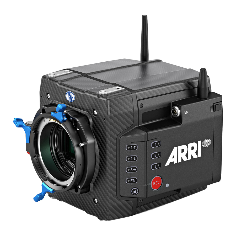
Page 21: Camera Body Overview
Camera Buttons VF Viewfinder Connector WiFi Antenna Connector Media Door Release Camera Status LED Camera Front ARRI LPL Mount (LBUS) LBUS Connector (on Lens Mount) Lens Mount Contacts Built-in Microphone (right) Built-in Microphone (left) WiFi Antenna Connector VF Viewfinder Connector... - Page 22 Camera Body Overview Camera Rear Boot Status LED POWER Button Camera Status LED Media Door Media Status LED Window WiFi Antenna Connector Fan Outlet White Radio Antenna Connector Rear Connectors Camera Top WiFi Antenna Connector VF Viewfinder Connector Attachment Points for Mechanical Acces- sories Camera Bottom LBUS Connector (on Lens Mount)
-
Page 23: Camera Rear Connectors
The audio connector is a 2-channel +24 dBu line level audio input with an additional regulated 12 V power output with a current of 0.5 A. Use the ALEXA Mini LF Audio connector with cable (K2.0023988) to connect audio sources. - Page 24 Tri-Level HD signals. BAT (8-pin LEMO) The BAT connector is the main power input of the ALEXA Mini LF and accepts an input voltage range from 11.0 to 34.0 V DC. You can use power cables KC50-S (K2.75007.0) or KC50-SP-S (K2.0001275) or one of the various on-board adapter plates for V-Mount and Gold Mount batteries to supply the camera with power.
-
Page 25: Camera Left And Front Connectors
WiFi Antenna Connector (RP-SMA) Besides the built-in WiFi antenna behind the camera label on the right side, the ALEXA MINI LF is equipped with a second WiFi antenna connector above the media bay on the camera left side. Both internal and external WiFi antenna work together, and if needed, the external antenna output can be disabled in the camera menu. -
Page 26: Media Bay
Recording Media Slot The ALEXA Mini LF records clips onto Codex Compact Drives, using the media bay on the camera left side. A small window (3) in the media bay door shows the LED of the Compact Drive. To access the media slot, slide the media bay door release (2) towards the camera back so that the spring-loaded door jumps open. -
Page 27: Multi Viewfinder Mvf-2 Overview
Multi Viewfinder MVF-2 Overview Multi Viewfinder MVF-2 Overview Flip-out Monitor Diopter Adjustment Proximity Sensor ZOOM Button EXP Button PLAY Button VF 1&2 User Buttons Top Tally Light SET Button User Wheel LOCK Switch REC Button Dove Tail Service Cover Bottom Tally Light Product Label Viewfinder Connector Headphones Out... - Page 28 Multi Viewfinder MVF-2 Overview ADVICE Permanent Activation of the Viewfinder OLED Display Permanent activation can cause irreversible burn-ins on the viewfinder OLED display. Do not cover the viewfinder proximity sensor. When covered, the viewfinder OLED display will be switched on permanently. If you need to cover the viewfinder, disable the viewfinder OLED display first using the EVF Power setting.
- Page 29 K1.0024074 - XXXXX. Viewfinder Connector (CoaXPress) The ALEXA Mini LF uses an industrial CoaXPress interface to connect the MVF-2 viewfinder or the Camera Control Monitor CCM-1 with the camera. The interface transmits power, video and control data and supports cable lengths of up to 10 m (33 ft).
- Page 30 Multi Viewfinder MVF-2 Overview Adjusting the Flip-out Monitor Fold out, swivel and fold in the monitor to put the display visible in the folded-in position. The image on the monitor automatically adjusts its orientation, or can be set to the desired orientation in the camera menu.
-
Page 31: Camera Control Monitor Ccm-1 Overview
Headphones Connector USB Connector Mounting Points The monitor has four ARRI Pin-Lock 1/4“ mounting points (top (1), right (7), bottom & rear (11)), to attach the monitor to the camera or e.g. a rig. POWER Button The monitor can be switched on and off via the POWER button (2). - Page 32 SDI IN (BNC) When the MVF-2 and CCM-1 are used in parallel on an ALEXA Mini LF, or when the monitor is used with third party cameras, the CCM-1 receives the camera image via the SDI In connector (10). The SDI In connector accepts 1.5G and 3G SDI signals according to SMPTE ST 292-1:2012 and SMPTE ST...
-
Page 33: Camera Support
(K2.0014957, K2.0023546) ALEXA Mini, and also ALEXA Mini LF on camera right. The MSB-3 is a side bracket designed around the media bay of the ALEXA Mini LF and the new viewfinder connector on the camera left. Center Camera Handle CCH-2... - Page 34 Camera Support Mounting MAP-2A, BPA-4 and BP-8 ► Using a 3.0 mm Allen key, fasten the Mini Adapter Plate MAP-2 or MAP-2A (1) to the camera top attachment points with the four 3.0 mm hex screws. Tighten them cross- wise. ►...
- Page 35 ► Open the clamps on the top MAP-2A and attach the MVB-1 (4) 15 mm LWS rods to the top MAP-2A. CAUTION When installing ARRI accessories or third-party accessories (like e.g. lenses, mechanical accesories, electronic accessories) pay attention to the risk of crushing and always use the correct tools.
-
Page 36: Power Supply
Power Supply BAT IN The ALEXA Mini LF accepts an input voltage range from 11.0 to 34.0 V DC. The camera can be solely powered through the 8-pin LEMO BAT connec- tor located at the back of the camera. You can use the KC50-S (K2.75007.0) or KC50-SP-S (K2.0001275) power cable or one of the various on-board... - Page 37 As soon as the camera has finished the boot process, the boot status LED turns to solid blue. During the boot process, the ARRI logo is shown in the flip-out monitor of the MVF-2 (if connected). Switching Off the Camera ►...
-
Page 38: Lens Mounts
Lens Mounts Lens Mounts The ALEXA Mini LF is equipped with a universal lens mount base for interchangeable lens mounts allowing the use of various lenses. ARRI Large-format Lenses Signature Prime Lenses ARRI Rental DNA LF and 65 Format Lenses... - Page 39 Compatible with ARRI LDS-1 and Cooke /i. The adapter can be mounted either so that the LDS contacts are in the 12:00 position for ARRI lenses, or so that the LDS contacts are in the 3:00 position for Cooke lenses.
-
Page 40: Changing The Lens Mount
Lens Mounts 11.1 Changing the Lens Mount WARNING Changing the Lens Mount while the Camera is Powered Risk of electric shock and permanent damage to the camera and/or the lens mount. Always switch off the camera and disconnect all power supplies before changing the lens mount. - Page 41 Lens Mounts Removing a Lens Mount (here: LPL Mount) Required Tools and Precautions 3.0 mm Allen key Camera switched off and power source disconnected Lens removed and properly stored ► Switch off the camera and unplug power sup- ply. ► Crosswise, loosen all four lens mount screws with a 3.0 mm Allen key.
-
Page 42: Menu Operation
Menu Operation Menu Operation The camera settings are divided into 11 submenus: Recording Image User Buttons Info Media System Metadata Alerts Monitoring Setup Lens & ECS ► While the HOME screen is displayed, press the HOME / LIVE button (2) or swipe to the right to display the live view. - Page 43 = shutter angle / (360 x FPS). EI (Exposure Index) Shows the current exposure index. Base sensitivity for the ALEXA Mini LF is 800 ASA. Press the screen button to adjust the exposure index in a range from 160 to 3200 ASA.
- Page 44 WiFi is active and in client mode. The camera is connected to a network. is not connected to a network. The ARRI ECS White Radio is active and uses WiFi is active and in host mode. the displayed channel number.
-
Page 45: Working With Settings/Lists And Importing Files
Menu Operation 12.2 Working with Settings/Lists and Importing Files For certain settings, the camera menu operates with preset lists that come with a default content and that can be adjusted to the user's preference. You can add values to and delete values from these lists, so that only project relevant values are displayed. - Page 46 Menu Operation Importing Files For looks, frame lines, user setups and lens tables the camera offers the option to import files from the USB medium as well as from a factory default presets. To import files from a USB medium into the camera, the USB medium needs to be prepared with a certain folder structure, see chapter "User Storage", page 49...
-
Page 47: On-Screen Keyboard
Menu Operation 12.3 On-screen Keyboard When working with textual parameters on the camera, an on-screen keyboard serves to enter text. You need to use the keyboard, for example, to enter the name when saving a user setup. ► Use the jogwheel to select and enter charac- ters. -
Page 48: Overlay Menu
Menu Operation Function Button & Camera Function Button Starts/stops playback from the recording medium. During playback, the camera buttons control the following functions: Camera Button Function FN + 3 Skip backward Skip forward Play / Pause Toggles WiFi on/off. FN + 6 When pressing (just) the FN button, the status LED of button 6 reflects the current WiFi status (LED on = WiFi enabled). -
Page 49: User Storage
USB medium. ► Open the media door and insert the USB medium. ► Select MENU > Media > Prepare USB Medium to create the folder structure on the USB medium: ARRI/A-MINI-LF/ FRAMELINES for frame line imports to camera... -
Page 50: Info Screens
Menu Operation 12.7 Info Screens The INFO screens provide detailed information about the current state of the camera system. ► Select MENU > Info. The Info sub menu contains the following lists: Version Info Software The camera software version. Revision of camera software version. Revision FPGA Firmware version of active FPGA. - Page 51 Export HW Info File HW (HardWare) Info files are required to generate licenses in the ARRI License Shop or may be requested by camera service to get detailed information on the camera's hardware and components revisions.
-
Page 52: Status Information And Overlays
Status Information and Overlays Status Information and Overlays The camera displays camera status information on the EVF and the SDI outputs. At the top and bottom of the screen, the camera displays status information in text form. The top status bar displays the current settings of sensor FPS, shutter angle, exposure index, ND filter, and white balance. - Page 53 Status Information and Overlays 11 Display of the remaining capacity of the recording media at current sensor frame rate and codec, in real time. When media capacity is less than two minutes, capacity values starts flashing orange. 12 Display of the current timecode. The TC label turns orange if the sensor frame rate does not match the project rate. Status Info Left 13 EVF / SDI 1 / SDI 2 Status Output processing icons.
- Page 54 Overlays Center marker, marks the center of the image to help in framing. Frame line (here: ARRI 1:1.85) The focus distance overlay displays the current focus distance (if lens data is available). The distance measure overlay displays readings from distance measurement devices.
- Page 55 Status Information and Overlays Sub-option of Electronic Horizon. Shows the tilt and roll of the camera in degrees as Show Numeric Values measured by the camera's position sensor. Flip-out Monitor Status Bar The flip-out monitor of the MVF-2 shows a slightly different status information than the EVF and the SDI outputs.
-
Page 56: Main Parameters
Main Parameters Main Parameters The following chapter lists the most important parameters of the camera. 14.1 Project Settings The project settings menu contains settings that should be configured at the beginning of each project and can be found at MENU > Recording > Project Settings. Project Rate The project rate determines how many frames the timecode counts per second, and also determines the frame rate at which clips are played back. - Page 57 Main Parameters Camera Index Color Set the color of the camera index letter displayed in the Status Info of the SDI outputs (e.g. to match it to the color coding of your cameras). ► Select MENU > Monitoring > SDI > SDI Processing > Overlays > Status Components > Camera Index Letter to display the camera index letter in the SDI status info.
-
Page 58: Sensor Frame Rate
Main Parameters 14.2 Sensor Frame Rate The sensor frame rate determines the amount of frames generated by the sensor in one second. For sync sound recording, the sensor frame rate matches the project speed. If you record a clip at a higher sensor frame rate than the project rate, a slow motion effect occurs during playback. -
Page 59: Exposure Index
14.4 Exposure Index The Exposure Index (EI) is the applied sensitivity of the camera. The ALEXA Mini LF has a base sensitivity of 800 ASA. This means that the dynamic range is almost evenly distributed above and below neutral gray with low noise in the shadows and clean, smooth clipping behavior in the highlights. -
Page 60: Nd Filter
14.5 ND Filter The ALEXA Mini LF has a built-in motorized and sealed filter stage for Full Spectrum Neutral Density filters (FSND) with densities of 0.6, 1.2 and 1.8 (and an optical clear filter). In comparison to IRND filters, which have an uneven spectral behavior, or to an ordinary ND filter, which opens up at about 675 nm, the FSND filters offer a true, even light attenuation over the whole spectrum. - Page 61 Main Parameters Timecode Run Mode Rec Run timecode is often used on single camera productions that are either MOS or use a dumb slate to synchronize picture and sound. Rec Run timecode guarantees continuous timecode on all recorded data. The timecode increments only during recording, by one frame for each image generated by the sensor.
- Page 62 Main Parameters The camera samples the timecode from the timecode connector and simultaneously tunes Jam Sync its internal timecode clock to match the clock of the timecode source. During this procedure, the timecode display on the HOME screen, on the timecode menu screen as well as on the Status Info is blinking.
- Page 63 Main Parameters ADVICE The camera's internal battery will keep the timecode and timecode tuning values for about 5 minutes after the power source was disconnected.
-
Page 64: Look Settings
After recording, backup and data transfer, the look can be extracted from the clip’s file header using the ARRI Color Tool again. This way the look can travel to post production as an ARRI Look File 2 or as a 3D LUT. - Page 65 Please note that this is the currently enabled ARRI Look File 2, as the camera does not take into account which ARRI Look File 2 was active when the clip was recorded. It is the responsibility of the user to make sure the correct ARRI Look File 2 is applied during playback.
-
Page 66: Processing And Color Spaces
Select to apply the look set in MENU > Look > Look to the output path. Look Applies a video display processing to camera images. The default ARRI 709 look complies with the ITU.R-BT709 standard for display on standard broadcast monitors. -
Page 67: Noise Reduction
ARRI customers like. Using ARRI Noise Reduction ANR-1 enables you to use noise reduction on set in the camera. This can be helpful for low light shots, where an in-camera noise reduction is a very fast solution. Furthermore, ARRI Noise Reduction ANR-1 gives you the possibility to combine the amount of grain with your sharpness and detail settings for the chosen exposure directly on set. - Page 68 MXF/Apple ProRes files cannot be opened and altered in the ARRIRAW Converter (ARC). When recording MXF/ARRIRAW files, the ARRI Noise Reduction ANR-1 is applied for preview (viewfinder and SDI outputs) but not baked into the footage, instead it will be stored in metadata.
-
Page 69: Recording
The 2 TB drive offers about double speed for all ARRIRAW formats on ALEXA 35. There is no advantage other than capacity for the ALEXA Mini LF. At 24 fps ARRIRAW 4.6K 3:2 Open Gate, the recording time is a little over 25/50 min. At 24 fps Apple ProRes 4444 4K 16:9, the recording time is a... - Page 70 Recording The camera records its data to the ARRI UDF file system which is accessible for operating systems without the need for special software. Depending on performance vs budget requirements, you can choose between a USB-C Reader or a Thunderbolt 3 Dock. Mac users who own a SXR Capture Drive Dock can get a Compact Drive Adapter, which combines high performance with lower pricing.
- Page 71 This information only refers to clips that were recorded with an ALEXA 35 or an ALEXA Mini LF, but not to other files that the user has saved on the medium. ► Press ERASE twice to start erasing the medium, or press CANCEL to cancel.
-
Page 72: Recording Codec
ARRIRAW frame. This checksum is recorded as part of the image header and can be used by software like the ARRI Reference Tool, to verify that the ARRIRAW image content has not changed during any copy step. Note that this checksum does not validate the entire file, only the image data. Note that... -
Page 73: Recording Resolution
Recording 16.3 Recording Resolution Recording Resolution Naming Scheme Recording Codec The Recording Codec defines the image content encoding. The options are ARRIRAW or Apple ProRes. Sensor Mode The sensor mode defines the size of the area on the sensor that is read out. This influences the maximum possible frame rate, the maximum data rate and what lenses can be used, as some lenses may not cover a large sensor area. - Page 74 Recording Recording Resolutions ARRIRAW Recording Resolution Sensor Active Sensor Active Image Recording Recording Image Area Area Resolution Frame Rates (dimensions) (photosites) (Clip) 36.70 x 25.54 mm 4.5K LF 3:2 Open Gate - 4.5K 4448 x 3096 0.75 - 40 fps 1.445 x 1.006“...
- Page 75 Recording 4480 x 1856 36.70 x 15.31 mm (Clip padding: 4.5K LF 2.39:1 - 4.5K 0.75 - 60 fps 1.445 x 0.603“ 16px left and right) 35.64 x 20.05 mm 4.3K LF 16:9 - UHD 3840 x 2160 0.75 - 48 fps 1.403 x 0.789“...
- Page 76 Recording 23.76 x 17.81 mm 2.8K S35 4:3 - 2.8K 2880 x 2160 0.75 - 75 fps 0.935 x 0.701“ 23.76 x 13.36 mm 2.8K S35 16:9 - HD 1920 x 1080 0.75 - 100 fps 0.935 x 0.526“ ► Select Menu > Recording > Recording Resolution. ►...
-
Page 77: Starting Recording
Starting Recording The camera supports various ways to start and stop recording. Recording can be started and stopped The REC button on the camera body, the MVF-2 and ARRI hand units such as the WCU-4 and Hi-5 The Camera Companion App... -
Page 78: Audio Recording
Recording in another camera, it keeps its name, but a new folder with the according camera ID and reel number is created in the root folder of the medium. It is possible, but usually not necessary, to manually change the next reel number in the project menu. 16.6 Audio Recording The camera supports to record up to 4 channels of linear PCM audio (24 bit, 48 kHz). - Page 79 Recording Activation of Audio Recording ► Select MENU > Recording > Audio Recording > Audio Recording to enable/disable audio recording. Enabled audio recording is indicated through the audio meters displayed on the HOME screen as well as in the Status Info. The meters show the current level of the channel signal in dBFS. Audio recording is temporarily disabled if the frame rate of the sensor does not match the frame rate of the project.
-
Page 80: Rec Beeper And Tally
Recording Reference Tone A 1 kHz sine reference tone can be output on the SDI outputs and the headphone outputs of MVF-2. If a recording is started during this time, the test tone is also recorded in all active audio channels of the clip. -
Page 81: Playback
Playback Playback In-camera playback plays back the clips on the recording media at their project frame rate and is output to EVF, Monitor, SDI 1 and SDI 2. Playback can be controlled from a variety of locations such as the MVF-2, the Web Remote, the Camera Companion App or hand units such as the Hi5. - Page 82 Playback The Play End Mode defines the behavior when playback reaches the end of a clip. ► Select PLAY > Options. Following options are available: Pause on end Playback pauses at the end of the clip. Pause on start Playback pauses at the beginning of the clip. Playback continues from the beginning of the same clip again.
-
Page 83: Monitoring
Monitoring Monitoring 18.1 Surround View Surround View displays additional pix- els outside the captured image area (1), allowing the operator to see out- side the captured image and keep un- wanted objects, such as microphone booms, out of the shot. The Surround View area (2) is separated from the captured image area by the Surround Mask (here: 75% Mask). -
Page 84: Magnification
Monitoring Frame Border The Frame Border setting helps to visually separate the recorded image area from the status overlays for those recording resolutions that do not support to display surround view (e.g. 4.5K LF 3:2 Open Gate - 4.5K). ► Select MENU > Monitoring > VF > Frame Border to configure Frame Border for the EVF. Select MENU >... -
Page 85: Frame Lines
Monitoring Info: Magnification can only be applied on the SDI output(s) with SDI Image set to Processed. Magnification is not available when using 2K or HD Recording Resolutions. Magnification is reset to 100% when Recording Resolution is changed. 18.3 Frame Lines To aid in framing, the camera offers to display frame lines overlaid over the live image. - Page 86 Monitoring ► Select MENU > Monitoring > SDI > SDI Processing > Overlays > Frame Lines to toggle display of frame lines and center mark on the SDI outputs. User Buttons VF Frame Lines and SDI Frame Lines support to quickly enable/disable dis- play of frame lines for the corresponding output.
-
Page 87: Exposure Tools
Monitoring Adjusts the user rectangle width in the range of 0-999. Width Adjusts the user rectangle height in the range of 0-999. Height Offset Left Adjusts the horizontal user rectangle offset in the range of 0-1000. Offset Top Adjusts the vertical user rectangle offset in the range of 0-1000. Reset All Resets all values. - Page 88 Monitoring Exposure Signal Level Color 100% - 99% White Clipping Just below white clipping 99% - 97% Yellow 56% - 52% One stop over medium gray ( Pink Caucasian skin Green 18% medium gray 42% - 38% Just above black clipping 4.0% - 2.5% Blue 2.5% - 0.0%...
-
Page 89: 18.4.2 Zebra
Monitoring 18.4.2 Zebra In Zebra mode, the camera overlays up to two luminance ranges with diagonal stripes. High zebra ranges above, Mid zebra around the user defined luminance value. Zebra Configuration ► Select MENU > Monitoring > Exposure Tools > VF Exposure Tool and select Zebra to use Zebra as exposure tool for EVF and Monitor. -
Page 90: Peaking
Monitoring 18.5 Peaking Peaking highlights in-focus areas for better focus control. Peaking Mode ► Select MENU > Monitoring > Peaking > VF Peaking Mode to set the preferred peaking mode for EVF and Monitor. ► Select MENU > Monitoring > Peaking > SDI Peaking Mode to set the preferred peaking mode for the SDI outputs. -
Page 91: Zoom
Monitoring 18.6 Zoom The camera supports to zoom into the image e.g. to better judge focus. Zoom is essentially a shortcut to quickly achieve maximum Magnification. The camera offers six zoom positions: center, top left, top center, top right, bottom right and bottom left. While Zoom is activated, the zoom position can be changed by using the jogwheel, the soft buttons on the MVF-2 (if the Monitor is flipped out and set to display the live image) or through user buttons. -
Page 92: Sdi Settings
Monitoring 18.7 SDI Settings SDI Image The setting for the SDI image determines whether the SDI image is output as a clean feed or including status information and status overlays. ► Select MENU > Monitoring > SDI > SDI 1 Image. ►... -
Page 93: Preventing Damage To Sdi Outputs
Problem Description Camera SDI outputs can get damaged when an accessory is connected to the SDI output and is powered through an unshielded cable. All cameras, including all ARRI cameras and other SDI devices, can be affected by this. This is especially critical for cameras with SDI connections capable of SDI 6G or higher (even if set to work at lower bit rates like SDI 1.5G). - Page 94 Monitoring ADVICE Always make sure to plug in the power cable first and then connect the BNC cable. Once power and BNC cables are connected, it is OK to power the camera or accessory on or off. Always make sure to disconnect the BNC cable first and then disconnect the power cable. Only use shielded power cables to power accessories that connect to the camera with a BNC cable.
-
Page 95: Evf And Flip-Out Monitor Settings
Monitoring 18.9 EVF and Flip-out Monitor Settings EVF Brightness The brightness of the EVF is adjustable with values 120, 200 and 300 (Nits). ► Select MENU > Monitoring > VF > Settings > EVF Brightness to set the brightness of the viewfinder OLED between 120, 200 or 300. -
Page 96: 18.10 Sdi Color Bars
Monitoring Flips the Monitor image automatically depending on the monitor's orientation. This is the default setting. Auto Ignores the Monitor's orientation sensor and displays the Monitor image in normal orientation. Normal Flipped Ignores the Monitor's orientation sensor and displays the monitor image in flipped orientation (upside down). -
Page 97: User Buttons
CCM-1 (1-4). to assign the user buttons of HI-5 and WCU-4 (1-6). Hand Unit User Buttons to assign the user buttons of ECS devices like the ARRI Mas- LBUS Device User Buttons ter Grips and the OCU-1 (1-12). - Page 98 User Buttons Toggles the Monitor between normal and flipped mode. Flip Monitor To return to automatic operation, press and hold the user button for two seconds. SDI Check Log C Temporarily set SDI processing to Log C. Supports smart behaviour. SDI Desqueeze Toggles anamorphic desqueeze on the SDI outputs on/off.
- Page 99 User Buttons Decreases gain of audio channel 1 in 1dB steps. Audio Ch1 Decrease Info: User button is only functional with channel 1 control set either to Manual or Manual (+L). Increases gain of audio channels 1+2 simultaneously in 1dB steps. Audio Ch1+2 Increase Info: User button is only functional with channel 1 and channel 2 control set either to Manu- al or Manual (+L).
- Page 100 User Buttons Some user button functions support smart behavior. For these, a short press (i.e. less than half a second) toggles the function, while a long press (i.e. longer than half a second) activates the function only temporarily, as long as the user button is pressed. Assume a user button is configured with EVF Zoom: Short press of user button: EVF zoom is activated and stays activated.
-
Page 101: Synchronization
Synchronization Synchronization The camera's sensor and SDI outputs can be synchronized to either a genlock signal (a tri-level HD signal or an analog black burst signal) present at the BNC SYNC IN connector or a timecode signal present at the 5-pin LEMO TC connector. The camera's sensor needs to run at equal or double the frame rate of the reference signal to establish synchronization. -
Page 102: Ext Sync
20.1 EXT Sync Up to 16 ALEXA Mini LF cameras can be synchronized for various applications requiring sensor synchronization. One camera is set as the host camera and the other cameras function as client cameras. Cameras can be connected to each other via the EXT connector, using the MINI-EXT-sync cable (K2.0009051) and the EXT Distribution Box EDB-2 (K2.0013145). - Page 103 Synchronization EXT Sync Mode One camera is functioning as the host camera and the other camera(s) as client camera(s). A client camera can be a sensor client (only sensor synchronized) or a settings client (sensor and settings synchronized). ► Connect the cameras via their EXT connector using the MINI-EXT-sync cable(s) and the EXT Distribution Box EDB-2.
- Page 104 Synchronization ► When using settings client, each camera in the setup needs to use an individual camera ID prefix. Select MENU > Recording > Project Settings > Camera ID Prefix and select an individual prefix for each camera (usually giving the host camera the camera ID prefix “A”) Media Status with EXT Sync The host camera calculates the overall remaining recording time based on the media with the lowest capacity in the cluster.
- Page 105 Synchronization A001_CH8B A001_AH8B A001_C001_190705_AH8B A001_C001_190705_CH8B A001_C002_190705_AH8B A001_C002_190705_CH8B A001_C003_190705_AH8B A001_C003_190705_CH8B A001_BH8B A001_DH8B A001_C001_190705_BH8B A001_C001_190705_DH8B A001_C002_190705_BH8B A001_C002_190705_DH8B A001_C003_190705_BH8B A001_C003_190705_DH8B Info: Do not mix sensor and settings clients as this will cause inconsistencies in clip naming.
-
Page 106: Sensor Settings
When shooting ARRIRAW, it is not necessary to load the User Pixel Mask into the camera. Instead, it can be applied to the ARRIRAW files in post production using the ARRI Reference Tool or any third party software that has implemented the User Pixel Mask feature through the ARRI Image SDK. - Page 107 Sensor Settings ► Use the ARRI Reference Tool to mark defect pixels. The marked pixel coordinates are stored in an XML file called the User Pixel Mask. Please note that it is advisable to mark the least number of pixels necessary, as too many marked pixels can be counter productive.
-
Page 108: System Settings
System Settings System Settings 22.1 Language Setting ► Select MENU > System > Language to set the system language between English and Chinese (simplified). 22.2 System Time and Date ► Select MENU > System > System Time + Date to set the system time and date. Info: Timezone and Daylight Saving Time do not change time and date settings. -
Page 109: Battery Warning
System Settings 22.5 Battery Warning You can adjust the voltage level at which a power warning is displayed for the power source connected to the BAT connector. The level can be adjusted to match the battery type used. The default warning value is 13.5 V. -
Page 110: Update
Update key (*.lic) Release notes ► Carefully read the release notes. ► Copy the update file (*.SUP) to the ARRI/A-MINI-LF/SUP folder on the USB stick. ► Copy the update key (*.lic) to the ARRI/A-MINI-LF/LICENSES folder on the USB stick. Camera Update ►... -
Page 111: 22.7.3 Update Of Lbus Devices
LBUS devices such as cforce mini motors, cforce Plus motors, ARRI Master Grips, ARRI Operator Control Unit OCU-1 and ARRI LCUBE can be updated by the camera. The update requires an update file which can be downloaded from the ARRI website. -
Page 112: User Setups
The camera loads the selected user setup and shows a result message. The pop up highlights the parameters that you should check in case certain parameters could not be loaded. Factory Reset You can reset the camera to the ARRI factory default values. ► Select MENU > Setup > Factory Reset. ► Press RESET. -
Page 113: User Setup Parameter Blocks
User Setups 23.1 User Setup Parameter Blocks The camera allows you to store a full camera configuration by selecting all parameter blocks, or only parts of the configuration by de-/selecting the desired blocks. The parameter blocks have been chosen to allow for maximum flexibility while keeping coherent sets of parameters and minimizing the amount of potential conflicts by loading partial setups. -
Page 114: Network
Network Network A network connection can be used to remotely control the camera. The camera's Web Remote, the Camera Companion App or other applications communicating with the camera via the Camera Access Protocol (CAP) can be connected to the camera via Ethernet or WiFi. The camera is equipped with two WiFi antennas, one external an- tenna above the media bay (1) - Page 115 Network The camera acts as an WiFi access point. The SSID of the camera is “Mini-LF-xxxxx”. Host (xxxxx is the five digit serial number of the camera) Client The camera can connect to a WiFi network and receives it's IP address via DHCP. Icons on the HOME screen and the Status Info indicate the WiFi status: Host mode is enabled.
-
Page 116: Ethernet Settings
Network Connect to a Network using a QR Code (Client Mode) You can use a QR code to connect to a WiFi network. The WiFi credentials need to be provided in the following format: WIFI:S:my-ssid;T:[WEP|WPA|WPA2];P:my-password;; where the italic parts need to be replaced with your network credentials. ►... -
Page 117: Metadata
3rd parties to gain direct access to the embedded metadata in their tools. Through AMB we’re closely working with VFX tool manufacturers for years now to enable and enhance their systems to auto-sense e.g. lens data in ARRI original camera negatives and use it to trigger e.g. a de- focus effect. - Page 118 Metadata ADVICE Export laws dictate that for sensors made up of more than a certain number of photo sites, we cannot record positional information like tilt and roll, lest the camera be classified as military equipment. This rule looks at the total number of photosites on the sensor and does not concern itself with individual recording formats that may record fewer photosites.
-
Page 119: Lens & Electronic Control System (Ecs)
Lens & Electronic Control System (ECS) Lens & Electronic Control System (ECS) 26.1 Changing a Lens ADVICE Risk of damage and injury when using lenses exceeding the supported entry depth! LPL mount lenses with more than 18.00 mm entry depth and PL mount lenses with more than 38.50 mm entry depth might damage the camera's internal filters. -
Page 120: Lens Data
The Lens Data System (LDS) allows ARRI cameras and accessories to identify connected lenses and exchange dynamic lens data reflecting the current lens settings. It works with cine lenses using ARRI LDS or LDS-2 technology, lenses using Cooke /i technology and even cine lenses without lens data capabilities. -
Page 121: Lens Data Archive
These files are available from the Lens Data Archive (LDA), a local library of lens files, which can also be extended by the user. The LDA exists in ARRI cameras or accessories like the UMC-4, RIA-1, or cforce mini RF or in the ECS sync app for iOS. -
Page 122: White Radio Configuration
ARRI Wireless Com- pact Unit WCU-4 or ARRI Single Axis Unit SXU-1. The radio sys- tem is called white radio. The white radio antenna connector is located at the camera rear (1). - Page 123 Lens & Electronic Control System (ECS) Radio Power and Radio Channel ► Select MENU > Lens & ECS > Radio > Power to enable white radio. ► Select MENU > Lens & ECS > Radio > Channel to select the white radio channel. Following options are available: Channel Frequency...
- Page 124 Lens & Electronic Control System (ECS) ADVICE Please ensure that the region is configured correctly, as it may be illegal to use White Radio in a region other than specified in the setting. All settings are compliant to FCC and IC regulations.
-
Page 125: Lens Motors
LBUS connector of the lens mount and can be daisy chained. For more information about lens motors, please download the lens motor user manuals from the Lens Motors section of the ARRI website. Motor Calibration CAUTION Rotating Lens Motor Risk of crushing fingers and capturing and unraveling long hair, jewelry and/or clothing. -
Page 126: Ef Lens Iris Adjustment
This option is only available when the camera is equipped with an EF Mount. Furthermore, the iris of EF lenses can be controlled using the ARRI Master Grips or the Operator Control Unit OCU-1. ► Select HOME > EI > Iris. -
Page 127: Remote Control
Remote Control Remote Control 27.1 Web Remote The camera can be remotely controlled via WiFi or Ethernet using the camera's Web Remote feature. ► Connect the camera to your computer via WiFi or Ethernet. ► Open a web browser and enter the URL http://mini-LF-xxxxx.local (replace xxxxx with the camera's 5-digit serial number). -
Page 128: Camera Access Protocol (Cap)
27.2 Camera Access Protocol (CAP) The Camera Access Protocol (CAP) is an IP based API used to control and monitor ARRI cameras via a network connection. The protocol incorporates functions to perform color grading, query and set values like exposure index or sensor frame rate, start and stop recording and many more. Information on the Camera Access Protocol is available through the ARRI Partner Program free of charge. -
Page 129: Camera Companion App
M1 and M2 Mac computers and the Apple watch. 27.4 Hand Units Hi-5 and WCU-4 The ARRI hand units Hi-5 and WCU-4 support to control basic settings of the camera. The following settings can be accessed through the hand units: Rec start/stop... -
Page 130: Transvideo Starlite Hd5-Arri Monitor
The Transvideo Starlite HD5-ARRI monitor (K2.0006960) is a 5“ 3G-SDI OLED monitor with an integrated H.264 recorder, a touchscreen and a special ARRI bus interface to communicate with the camera. It allows basic operation of the camera. All overlays required for touch operation are generated by the camera and transferred to the Starlite monitor via HD-SDI. - Page 131 Transvideo Starlite HD5-ARRI Monitor User Setup Menu In the load user setup menu, you can load user setup files that have been stored on the camera. ► Activate the menu by pressing the blue “A” touch icon on the monitor.
-
Page 132: Appendix
Appendix Appendix 29.1 Sensor Related Information / 有关影像传感器的信息 Single Frame Spots of Various Shape – also known as “Digital Dust” or “White Flecks” Natural and/or artificial radiation may cause a “false exposure” on the image sensor. The shape of these spots may vary from dots to lines or other, sometimes irregular shapes. These spots occur in random locations of the image, last only for a single frame and are more visible in dark images. - Page 133 曝光时间越长,这些像素会变得越多。当曝光时间长于 1/24 秒时,请仔细检查画面是否符合您的要求。 Stitching with ALEXA Mini LF The ALEXA Mini LF sensor consists of a large sensor structure that is created by exposing two Super 35 sensor structures side by side onto a silicon wafer. This process is, somewhat misleadingly, called “stitching”.
-
Page 134: Companion Tools
29.2 Companion Tools ARRI maintains various tools to support your work with the ALEXA Mini LF on- and off-set. In the following overview, some of the tools are highlighted “online only” (green border) the others are available as download for Linux, macOS or Windows. - Page 135 Look Up Tables are still needed to convert ARRI’s Log C to a viewable format (e. g. REC 2020 or REC 709) or an otherwise needed format (conversion to linear space for VFX). Our LUT Generator can create the LUT you need.
-
Page 136: Connector Pin-Outs
Appendix 29.3 Connector Pin-Outs Info: All pin-outs for camera interfaces appear as seen by the user. BAT (LEMO EEJ.2B.308) RS (Fischer DPB102A052-130) Batcom Powergnd Powergnd Powergnd 24 V Aux Batcom Gnd Batplus Batplus Batplus 12V (LEMO EEG.0B.302.CLN.A365) AUDIO (LEMO EEA.0B.306.CLN) CH 1 (+) CH 1 (-) 12 V Aux... - Page 137 GND white-green DTR orange CTS white-orange Audio Cable K2.0023988 ARRI offers an ALEXA Mini LF / ALEXA 35 audio cable with a matching connector to create audio adapters. The following table shows the wire assignments of this cable. Function Wire...
-
Page 138: Cleaning Instructions
If the sensor cover glass has been contaminated by particles or smear, special optical cleaning kits should be used for dirt removal under very high care. If the contamination cannot be removed, the camera should be taken to an ARRI Service center for cleaning. -
Page 139: Repair
Repairs carried out by Untrained Personnel Risk of electric shock and fire caused by short circuit. Do not try to repair the device yourself. Repairs may only be carried out by authorized ARRI service partners. For repairs and maintenance work on the camera system, please contact "ARRI... - Page 140 Appendix ARRI Inc. / West Coast ARRI Inc. / East Coast 3700 Vanowen Street 617 Route 303 CA 91505 Burbank NY 10913 Blauvelt +1 818 841 7070 +1 845 353 1400 Business hours: Business hours: Mo. - Fr. 09:00 am- 05:00 pm (PT) Mo.
- Page 141 Appendix CINEOM Broadcast DMCC. CINEOM Broadcast India Pvt. Ltd. Unit No. 2109, Jumeirah Bay Tower X2 Cluster X C-4, Goldline Business Centre Jumeirah Lakes Towers Link Rd. Malad West P.O Box 414659 400 064 Mumbai Dubai, UAE India +971 (0) 45570477 +91 (0)22 42 10 9000 Business hours: Business hours:...
- Page 142 ALEXA Mini LF CAMERA DIMENSIONS – Version 2019-07 Technical Data are subject to change without notice. Camera Right Camera Front Image Plane Optical Center 129.9 mm 49,45 mm 142.92 mm 5.11” 1.95” 5.63” 68.65 mm 2.70” Optical Center 45.2 mm 62.42 mm...
- Page 143 ALEXA Mini LF CAMERA DIMENSIONS – Version 2019-07 Technical Data are subject to change without notice. Camera Left Camera Top Image Plane 179.28 mm 7.06” 153.72 mm 6.05” (mount contact surface to camera back) 148.35 mm 5.84” 28.96 mm 1.14”...
Need help?
Do you have a question about the ALEXA Mini LF and is the answer not in the manual?
Questions and answers