ARRI ALEXA User Manual
For alexa software update packet 3.0
Hide thumbs
Also See for ALEXA:
- User manual (189 pages) ,
- Pocket manual (130 pages) ,
- Quick manual (9 pages)
Table of Contents
Advertisement
Quick Links
Download this manual
See also:
User Manual
Advertisement
Table of Contents

Subscribe to Our Youtube Channel
Related Manuals for ARRI ALEXA


Summary of Contents for ARRI ALEXA
- Page 1 User Manual ARRI ALEXA For ALEXA Software Update Packet 3.0 Printed on 11 February, 2011...
- Page 2 Due to continued product development this information may change without notice. The information and intellectual property contained herein is confidential between ARRI and the client and remains the exclusive property of ARRI. If you find any problems in the documentation, please report them to us in writing. ARRI does not warrant that this document is error-free.
-
Page 3: Table Of Contents
Contents 1 Disclaimer 2 Scope 3 ALEXA Images 4 Introduction to ALEXA 5 About This Manual 6 Safety Instructions Explanation of Warning Signs and Indications ....14 General Safety Instructions ........... 14 Specific Safety Instructions ........... 15 7 General Precautions Storage and Transport............ - Page 4 Contents 9.3.2 Viewfinder Mounting Bracket ..........29 Center Camera Handle CCH-1 ..........31 Side Camera Handle SCH-1........... 32 Bridge Plate BP-12..............33 Bridge Plate adapter BPA-1 ........... 34 Wedge Adapter WA-1 + Quick-Release Plate ...... 35 Leveling Block LB-1 ..............35 9.10 Shoulder Pad SP-3 ..............
- Page 5 12.1.3.7 WB ................... 60 12.1.4 Function Buttons ..............61 12.1.4.1 TC (Time Code) ............... 62 12.1.4.2 INFO..................65 12.1.4.3 USER..................68 12.1.4.4 PLAY ..................70 12.1.5 Menu..................72 12.1.5.1 Recording ................72 12.1.5.2 Monitoring ................76 12.1.5.3 Project..................80 12.1.5.4 System..................82 12.1.5.5 Frame grabs ................
- Page 6 Neither ARRI nor its subsidiaries assume any liability for infringement of patents, copyrights or other intellectual property rights of third parties by or arising from the use of ARRI products or any other liability arising from the use of such products. No license, express, implied or otherwise, is granted under any patents, copyrights or other intellectual property right of ARRI or others.
- Page 7 Disclaimer Explanation of Warning Signs and Indications 7 ARRI is a registered trademark of Arnold & Richter Cine Technik GmbH & Co Betriebs KG. Note: This product and the accessories recommended by the manufacturer fulfill the specifications of the European Directive 2004/108/EC (15th December 2004).
- Page 8 8 Scope Explanation of Warning Signs and Indications Scope This instruction manual applies to the following hardware, software and firmware versions: ARRI ALEXA camera with ARRI EVF-1 electronic viewfinder • Camera software update packet (SUP): • EVF-1 software packet: 1.26...
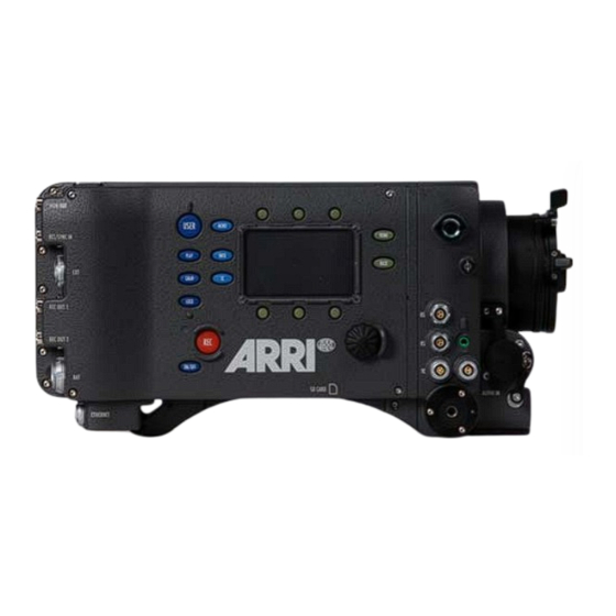
- Page 9 ALEXA Images Explanation of Warning Signs and Indications 9 ALEXA Images Figure 1: Camera right side Figure 2: Camera left side Figure 3: Camera top...
- Page 10 10 ALEXA Images Explanation of Warning Signs and Indications Figure 4: Camera bottom Figure 5: Camera front Figure 6: Camera back...
- Page 11 Explanation of Warning Signs and Indications 11 Introduction to ALEXA ALEXA is a 35 format film-style digital camera made by ARRI, the world leader in professional cinematographic imaging. It combines leading edge digital technology with film camera features that have been refined over more than 90 years of ARRIs history.
- Page 12 The fan itself is very silent, so the camera noise level is below 20 dB (A)* - this is the same as with ARRI sync-sound film cameras. If the fan noise level starts to increase due to fan aging, the fan can be swapped in a matter of minutes by a trained technician.
- Page 13 Explanation of Warning Signs and Indications 13 About This Manual It is recommended that all users of the ALEXA camera read the manual front to back prior to the first usage. The manual's structure also provides quick access for reference to experienced users. All directions are given from an operator's point of view.
-
Page 14: Safety Instructions
• Do not use accessories or attachments that are not recommended by ARRI, as they may cause hazards and invalidate the warranty! • Do not attempt to repair any part of the system! Repairs must only be carried out by authorized ARRI Service Centers. -
Page 15: Specific Safety Instructions
Safety Instructions Specific Safety Instructions 15 Specific Safety Instructions • Do not remove any safety measures from the system! • Do not operate the system in areas with humidity above operating levels or expose it to water or moisture! • Do not cover the fan openings at the camera back top and bottom! •... - Page 16 If the sensor cover glass has been contaminated by solid dirt or grease, special optical cleaning kits should be used for dirt removal under very high care! If the contamination cannot be removed, the camera should be taken to an ARRI service center for cleaning. •...
-
Page 17: General Precautions
Electromagnetic Interference ALEXA meets EC regulations by fulfilling the specifications of the European Directive 2004/108/EC (15th December 2004). This equipment has been tested and found to comply with the limits for a Class A digital device, pursuant to part 15 of the FCC Rules. - Page 18 To reduce the risk of condensation: • Find a warmer storage location. • Attach the ARRI air-drying cartridge (silica bottle) to the PL-Mount of the camera during storage (NOT during transport!) • If camera needs to be stored in a place that is considerably cooler...
-
Page 19: Power Supply
Manipulation of power supplies can result in severe damage to the equipment and humans, including death. ALEXA accepts an input voltage range from 10.5 to 34 V DC. The camera can be powered through the BAT connector or can be quipped with battery adapters accepting V-Lock or Gold Mount batteries. -
Page 20: Bat Connector
Note: The NG 12/24 R was the original design that provided 12 & 24 volts output – it was superseded by the NG 12/26 R, which outputs 12 & 26 volts. The NG 12/24 R can easily be upgraded to NG 12/26 R specification at an ARRI service center. -
Page 21: Onboard Batteries
Power Supply Onboard Batteries 21 To connect the battery to the camera: • Ensure that the main switch on the camera is off. • Plug the battery cable KC-20S or KC-29S (spiral cable) into the power supply socket on the camera and the battery 28 V output socket. -
Page 22: V-Lock Batteries
V-Lock batteries are available from a number of manufacturers. V-Lock batteries from ID-X transmit information on their remaining capacity to the camera. ALEXA displays the remaining capacity in percent on the Homescreen of the camera display. For ID-X batteries, the user does not need to set the battery warning level due to the communication of camera and battery. -
Page 23: Gold Mount Batteries
Gold Mount is the battery mounting system of Anton Bauer batteries. The batteries transmit information on their remaining capacity to the camera. ALEXA displays the remaining capacity in percent on the Homescreen of the camera display. For Gold Mount batteries, the user does not need to set the battery warning level due to the communication of camera and battery. -
Page 24: Power Outputs
24 Power Supply Power Outputs • Move the battery left, then pull it towards you and remove it. Figure 9: Camera with BAB-G and a Gold Mount battery Note: Not all Gold Mount batteries deliver enough power to supply the camera. We recommend to not use any batteries with a capacity of less than 90 Wh to prevent damage to the battery and unpredictable camera behavior. -
Page 25: Accessories
Power Supply Power Outputs 25 8.8.1 12 V Accessories The 12 V output is located on the right side of the camera and has a 2- pin LEMO connector. It is limited to 12V and can supply a device with a current of up to 2.2 A, depending on the camera power supply. -
Page 26: Installation Of The Camera
Sony SxS-PRO card for recording Tripod and Remote Heads Tripod and remote heads used with ALEXA have to provide enough load capacity to support the camera and attached accessories. The table to the right shows the camera weight for different components. -
Page 27: Electronic Viewfinder Evf-1
Installation of The Camera Electronic Viewfinder EVF-1 27 Viewfinder Cable short KC-150S 0.26 0.12 Center Camera Handle CCH-1 0.60 0.27 Electronic Viewfinder EVF-1 The EVF-1 employs an LCOS imaging device together with a temperature stabilized LED light source to provide an accurate and bright view of the sensor image under all operating conditions. -
Page 28: Viewfinder Cables
28 Installation of The Camera Electronic Viewfinder EVF-1 The viewfinder is connected to the camera with the mounting bracket VMB-1. Figure 11: Camera with EVF-1 Note: Do not point the viewfinder eyepiece at direct sunlight or bright light sources, as this could damage the LCOS imaging device. If possible, cover the eyepiece when not in use to prevent any damage. -
Page 29: Viewfinder Mounting Bracket
Installation of The Camera Electronic Viewfinder EVF-1 29 Figure 12: EVF cables: KC-150S (center), KC-151S (middle), KC-152S (outer) 9.3.2 Viewfinder Mounting Bracket The viewfinder mounting bracket VMB-1 is attached to the camera with two 3mm Allen screws at the very front of the camera top. The viewfinder is attached to the mounting bracket by sliding the dove tail into the receptacle of the mounting bracket and then closing the lever on the viewfinder. - Page 30 EVF further back. It can be attached to a tripod head for use with geared heads or greater comfort when using fluid heads. The VEB-1 has a standard attachment point for the ARRI eyepiece leveler EL-3. When using the VEB-1 with an eyepiece leveler, loosening the friction where the VEB-1 and the VMB-1 are joined is critical as tiliting can the damage the friction setting.
-
Page 31: Center Camera Handle Cch-1
Installation of The Camera Center Camera Handle CCH-1 31 Center Camera Handle CCH-1 The Center Camera Handle CCH-1 is attached to the camera top with 3 screws, two at the front and one at the back. Make sure the screws are well tightened with a 3mm Allen key. -
Page 32: Side Camera Handle Sch-1
32 Installation of The Camera Side Camera Handle SCH-1 The handle extension block HEB-2 mounts to the front end of the CCH-1 and adds one more focus hook to the camera in a high position, so the tape measure clears the matte box. Side Camera Handle SCH-1 The SCH-1 is used in conjunction with a BAT-V or BAT-G battery top mounting adapter, or with third-party onboard recorders. -
Page 33: Bridge Plate Bp-12
Figure 18: Camera with SCH-1, side view Bridge Plate BP-12 The bridge plate BP-12 has been newly developed for ALEXA. It mounts directly to the camera housing with two screws and ensures that iris rods, matte boxes and follow focus units are positioned properly in regards to the optical center of the camera, just like all other ARRI cameras. -
Page 34: Bridge Plate Adapter Bpa-1
Bridge Plate adapter BPA-1 The bridge plate adapter BPA-1 can be used to attach a BP-3/BP-5/BP- 8/BP-9 to ALEXA. First attach the BPA-1 to the camera with the two screws. Then attach the bridge plate to the adaptor with its two screws. -
Page 35: Wedge Adapter Wa-1 + Quick-Release Plate
Figure 19: ARRI QR-HD-1 Leveling Block LB-1 The leveling block LB-1 attaches to the bottom of the ALEXA back foot. It prevents the camera from resting on a back mounted battery when a bridge plate is attached and the camera is placed on a flat surface. -
Page 36: Shoulder Pad Sp-3
36 Installation of The Camera Shoulder Pad SP-3 9.10 Shoulder Pad SP-3 The camera base has an integrated arch to fit to the operator's shoulder. For extended handheld shoots, the newly designed shoulder pad SP-3 can be attached to the base of the camera with velcro. Note: The SP-3 can only be used with a BP-12 and 19 mm rods or with 15 mm rods and a WA-1+quick-release base plate. -
Page 37: Connectors
Connectors Shoulder Pad SP-3 37 Connectors Camera back Figure 23: Connectors at back From top to bottom: MON OUT, RET/SYNC IN, EXT, REC OUT 1&2, BAT, ETHERNET Camera right Figure 24: Connectors on right side From left to right, top to bottom: 2x RS (24 V) out, AUDIO OUT, TC, 12V out, AUDIO IN, SD CARD (camera bottom) - Page 38 38 Connectors Shoulder Pad SP-3 Camera left Figure 25: Camera left: SxS slots Top to bottom: SxS slot 1, SxS slot 2 Camera front Figure 26: Camera front connector EVF connector...
-
Page 39: Bat
Cables are currently available for: • Connecting a UMC-3 remote motor controller (model UMC Connection Cable (0.80m/2.6ft) K-UMC3-ALEXA) • Connecting two ALEXA cameras for synchronized operation (model EXT to EXT Cable (2.00m/6.6ft) KC 155-S) The connector is located on the camera back mid right. -
Page 40: Ethernet
Ethernet socket to a standard RJ-45 Ethernet socket. The ethernet port can be used to operate two ALEXA cameras with synced settings by connecting the cameras with cable KC 156-S. In addition it is used for service and future accessories. -
Page 41: Audio Out
Connectors TC 41 It is located on the camera right lower front. 10.11 TC The TC connector is a 5pin LEMO socket. It accepts and distributes LTC (Longitudinal Time Code) signals. It can be used to • Jam sync the camera time code to a Clockit, TC Slate or another camera •... -
Page 42: Sxs Slots
42 Connectors SxS Slots On the SD card, the folder structure presented in the following example should be created by the user prior to first use of the card. Figure 27: Folder structure required for SD card Firmware update files are recognized by the camera anywhere within the structure, but are still recommended to be placed in the Firmware folder. - Page 43 Card is unreadable (e.g. wrong file system) Card is inactive Solid green Card is selected and ready Solid red Card is accessed (read/write) !DO NOT REMOVE CARD! Only Sony SxS-PRO cards can be used with ALEXA. Sony SxS-One cards are not supported.
-
Page 44: Optics
11.1 Lens Adapter PL Mount LA-PL-1 (no LDS) The lens adapter LA-PL-1 is the standard lens mount delivered with ALEXA. It can be used to attach any modern PL-mount lens to the camera. Attaching a lens to the camera •... -
Page 45: Lens Support
Optics Lens Support 45 Figure 28: PL mount LA-PL-1 with index pin 11.2 Lens Support Heavy lenses may require additional lens support. This guarantees that the flange focal depth is not influenced by the lens weight and reduces stress on the lens mount. To support a lens 15mm studio or 19mm studio rods and a fitting lens bridge. - Page 46 46 Optics Lens Support When the bridge is in the right position on the rods, it is fixed with the screw or lever on its side. It is attached to the lens support ring with its center screw. The lever on the back of the lens bridge fixes the height of the center screw.
-
Page 47: Camera Controls
Camera Controls Main Controls 47 Camera Controls The camera can be controlled through three different interfaces: Main Located on the camera right side. Consist of a 3" LCD- controls screen with screen buttons changing their behavior depending on the screen content, a jogwheel to navigate through menus and adjust parameters and a range of function buttons with dedicated behavior. -
Page 48: Display
48 Camera Controls Main Controls 12.1.1 Display The LCD display on the right side has a size of 3" and a resolution of 400x240 pixels. The display is back illuminated and transflective which results in exceptional contrast even in bright sunlight. The brightness of the display can quickly be adjusted by simply turning the jogwheel when the Homescreen is displayed. - Page 49 5.0-358.0°. Shutter Angle and sensor fps determine exposure time of the sensor in seconds by the following equation: Angle/(360*Fps). Currently set exposure index rated in ASA. ALEXA has a base sensitivity of 800 ASA, the camera rating can be adjusted from 160-3200 ASA.
- Page 50 Apple ProRes, the codec family used for image encoding in ALEXA, is a variable bit rate codec, so the available recording time depends on the image content. It can well be that the available recording time exceeds the value displayed here.
-
Page 51: Lists And User Lists
Camera Controls Main Controls 51 Lock Camera is locked. SD Card SD card present. Turns orange when card is accessed. Grab Still frame is currently grabbed to the SD card. Tropical Sensor is in tropical mode (=40° C mode temperature) Note: A sensor temperature warning or error after bootup is normal until the sensor has reached its preset temperature. -
Page 52: Fps
52 Camera Controls Main Controls To select a list value, turn the jogwheel until the selection bar is on the desired value and press the jogwheel. Add a list value If the list lacks the required setting, press the ADD screen button. This opens a screen where the desired value can be set. - Page 53 Camera Controls Main Controls 53 The lower screen buttons are shortcuts to the menu screens of SxS CARDS, SxS INFO and REC OUT. Setting sensor fps through REC OUT fps If the sensor fps is linked to the REC OUT frame rate, a message appears instead of the list.
- Page 54 54 Camera Controls Main Controls If the REC OUT frame rate is higher than the sensor frame rate, duplicate frames are output on the REC OUT. For example, if the sensor is running at 10 fps and the REC OUT is set to 30 fps, every image is output 3 times, resulting in two duplicate frames following every active frame.
-
Page 55: Audio
Camera Controls Main Controls 55 12.1.3.3 AUDIO Pressing the AUDIO screen button in the Home screen opens the Audio screen. This screen shows the level on the two audio channels in the camera. The audio levels are displayed from -50 dB FS to 0 dB FS. Note: When audio is switched off or disabled, no meters are displayed, but a message shows OFF or DISABLED. - Page 56 56 Camera Controls Main Controls • Channel 1 level: Manual allows the user to manually apply gain to the input signal on channel 1 to reach a correct level. Unity matches a 4 dBu input signal to -20 dB FS. This setting leaves enough headroom for recording and avoids audio clipping.
-
Page 57: Shutter
Audio out level: Choose to determine the level of the audio out channels manually, or set it fix to the maximum output. Note: ALEXA automatically determines the internal signal run time and matches audio and images so they are always in sync. When changing sensor fps or project fps, it may take up to 2 seconds for the camera to resync image and audio signals. -
Page 58: Color
Note: The Exposure Index list has a fixed content, meaning that it cannot be changed by the user. ALEXA has a basic sensitivity of 800 ASA. This means that the dynamic range is almost evenly distributed above and below neutral grey with very low noise in the dark parts of the image and a very clean and smooth clipping behavior in the bright parts. - Page 59 Thus color grading becomes an obligatory post production step and for proper previewing, creation of dailies or editing proxies it is necessary to use Look Up Tables. Matching preview LUTs can be generated with the ARRI ALEXA LUT generator on www.arridigital.com.
- Page 60 60 Camera Controls Main Controls 12.1.3.7 WB Pressing the WB screen button in the HOMESCREEN opens the WBlist screen. The list presets are 3200K for Tungsten, 4300K for Fluorescent, 5600K for Daylight and 7000K for Daylight cool. White Balance adjusts the color balance of the camera according to the lighting in use.
-
Page 61: Function Buttons
Camera Controls Main Controls 61 White balance and color compensation should be adjusted only with the help of appropriate equipment. This can either be a color meter or a vectorscope together with a calibrated grey card. User entries of the WB list can be assigned a new name to match either the type of lighting used, or to match to a certain type of setup (e.g. -
Page 62: Tc (Time Code)
62 Camera Controls Main Controls INFO Enters the Status Info screen, where you get information on the system's state. Also available is version info, where you get information on camera hard- and firmware, storage info giving details about SxS-PRO cards, and system info. USER Enters the user screen, where you can assign the three user buttons of the operator controls, as... - Page 63 TC count and continues counting on its own. Due to a highly precise crystal oscillator in ALEXA, the internal counter will count accurately for 8 hours. After that period, the camera has to be resynced to avoid any TC offset.
- Page 64 64 Camera Controls Main Controls • Userbit source: shows the source of the user bits. Internal User bits are set manually in the User Bit screen. LTC in UB When using Ext LTC as TC source, the user bits are sampled from the external signal. Press the SET TC screen button to adjust the TC counter (only with Int TC as source).
-
Page 65: Info
Note: Saving a system log is only necessary if the camera is showing unnormal behavior. It can then be sent to the ARRI camera service for analysis. The log is not human-readable and can only be analyzed by the ARRI camera service. - Page 66 66 Camera Controls Main Controls Figure 44: VERSION info screen SxS CARDS Info Codec Currently set codec for internal recording. Status Current status of SxS-PRO cards in slot 1 and 2. Free Free storage space of SxS-PRO cards in percent. capacity Write speed Maximum write speed of the SxS-PRO cards.
- Page 67 Camera Controls Main Controls 67 Sensor Current temperature of image sensor. Target is temperatur 35°C in standard mode, 40°C in tropical mode. IP address IP address of the camera's Ethernet port. Figure 46: SYSTEM info screen FPS Info Gives an overview of all frame rates in the camera. Sensor fps Frames per second generated by the sensor.
-
Page 68: User
68 Camera Controls Main Controls 12.1.4.3 USER By pressing the USER button the USER screen is loaded where the screen buttons can be assigned with user defined functions. The upper three screen buttons of the USER screen mirror the behavior of the three assignable buttons on the camera left side (labeled 1, 2, 3). - Page 69 Camera Controls Main Controls 69 Mon out frame lines toggles frame lines of the MON OUT image on/off Mon out status info toggles status info of the MON OUT image on/off Mon out false color toggles false color display on MON OUT on/off Frame lines color toggles color of frame lines image on/off...
-
Page 70: Play
70 Camera Controls Main Controls 12.1.4.4 PLAY Clups that have been recorded to the SxS cards can be played back by the camera on EVF, MON OUT and REC OUT. Note: When the REC OUT signal cannot be used for playbackwhen it is set to ARRIRAW. - Page 71 Camera Controls Main Controls 71 To stop playback and return to the live image, press HOME or BACK. If you press REC, playback is stopped, recording is started and the Home screen is loaded. OPTIONS The OPTIONS screen button opens a list of general playback options. Figure 51: Play options screen •...
-
Page 72: Menu
72 Camera Controls Main Controls 12.1.5 Menu The menu contains parameters for the basic camera setup. It has a tree structure and the current path in the menu is displayed in the top section of every screen. To access a new menu level, select the group with the jogwheel and press the jogwheel. - Page 73 Camera Controls Main Controls 73 SxS CARDS ALEXA can internally record to Sony SxS-PRO cards. The card slots are located on the camera's left side. Codec Set the codec to be used for internal recording to SxS cards. Choose from the full range of Apple ProResTM codecs.
- Page 74 74 Camera Controls Main Controls Name Color Data Recording time max. coding rate @ on 32 GB SxS- frame 30 fps Pro @ 30 fps*** rate** ProRes YCbCr 45 Mb/s 1 h 23 min 60 fps (Proxy) ProRes YCbCr 102 Mb/s 37 min 60 fps 422 (LT)
- Page 75 Camera Controls Main Controls 75 The camera has two HD-SDI outputs that carry the camera image to be recorded with external recording devices. Note: Only use double shielded HD-SDI cables for recording to ensure error free data transmission! Frame rate Select the rate at which images are transmitted per second.
-
Page 76: Monitoring
High-speed recording with ALEXA over HD-SDI Unlike the ARRIFLEX D-21, which used a proprietary mode for high- speed recording, ALEXA complies with SMPTE standard 372M in terms of image transmission. This means that images are split into fields, and every field is transmitted over one link. - Page 77 Frame lines Frame lines are a reference for framing that typically consist of an image frame, a center mark and an aspect ratio reference. See the appendix for more information on the ALEXA frame line format.
- Page 78 78 Camera Controls Main Controls Center mark A center mark, either a cross or a dot can be added to the image to help the framing. Figure 57: MENU>MONITORING>EVF MON OUT The MON OUT is a 422 1.5G single link HD-SDI output. The output range is fixed to legal range.
- Page 79 Frame lines are a reference for framing that typically consist of an image frame, a center cross and an aspect ratio reference. See the appendix for more information on the ALEXA frame line format. Center mark A center mark, either a cross or a dot can be added to the image to help the framing.
-
Page 80: Project
Frame lines are an image overlay that can be applied to either the EVF image, the MON OUT image, or both. ALEXA frame lines are stored as XML files containing definitions what the frame lines look like. The camera contains default frame lines for 1.33:1, 1.66;1 1.78:1, 1.85:1 and 2.39:1 aspect ratios. - Page 81 Camera Controls Main Controls 81 Note: The user should set the value to 001 before a shoot begins. Figure 60: MENU>PROJECT Production Info The production info screen contains fields to enter info metadata regarding the production. The user can enter the names of the director, cinematographer, location and production.
-
Page 82: System
82 Camera Controls Main Controls 12.1.5.4 System Contains groups of system settings. Figure 62: MENU>SYSTEM Sensor Sensor When shooting in tropical conditions with high temperature temperature and humidity, the sensor temperature can be changed to "Tropical". This will avoid condensation on the sensor coverglass. Power BAT1 (Plug) The level at which a power warning is exhibited... - Page 83 Camera Controls Main Controls 83 Note: At a level 10% below the set warning level, a battery error is emitted. This means that the power source is treated as insufficient to power the camera any further. Figure 63: MENU>SYSTEM>POWER Smart batteries that transmit their remaining load to the camera emit a warning at 10% remaining capacity and an error at 5% remining capacity.
- Page 84 Influences naming of clips on SxS cards. Sensor sync The sensors of 2 ALEXA cameras can be synced. See Sensor sync (on page 103) for more info. • Off: The camera is in non-synced mode for regular use.
- Page 85 Camera Controls Main Controls 85 settings via Ethernet. See Settings sync (on page 104) for more info. Figure 66: MENU>SYSTEM>EXT SYNC Run beeper Figure 67: Run beeper screen The camera has a beeper to acoustically signal the start and/or stop of recording.
-
Page 86: Frame Grabs
86 Camera Controls Main Controls THE CAMERA POWER SUPPLY WILL REMAIN SUFFICIENT FOR THE DURATION OF THE UPDATE (APP. 15 MINUTES). Note: On rare occasions, the update process can fail. If the update procedure fails, try it again until you succeed. Figure 68: MENU>SYSTEM>FIRMWARE 12.1.5.5 Frame grabs By pressing the GRAB button, or by assigning the function "Grab still... -
Page 87: Operator Controls
Camera Controls Operator controls 87 Save current A setup containing the current camera settings is setup stored to the SD card. File is named with time and date stamp. Load setup Loads a list with all setups located on the SD card. -
Page 88: Evf Controls
88 Camera Controls EVF Controls User button 3. Can be assigned with functions through the USER button on the main UI. Starts and stops internal recording. LED tally goes red during record. PLAY Short press loads last clip. Short press again to toggle between play and pause. -
Page 89: Viewfinder Evf Menu
Camera Controls EVF Controls 89 Loads the false color display as long as the button is pressed. To keep it activated after the button press, press the ZOOM button while the EXP button is pressed. The false color display will remain active until the EXP button is pressed again. -
Page 90: Viewfinder Cam Menu
Frame lines are a reference for framing that typically consist of an image frame, a center cross and an aspect ratio reference. See the appendix for more information on the ALEXA frame line format. Select frame Choose the main frame lines template from those lines 1 stored in the camera. -
Page 91: Operation Of The Camera
This chapter contains in formation and recommendations for recording with SxS-PRO cards. The user is of course free to modify the recommended worksteps to his needs. Note: ARRI cannot be held responsible for the loss of any data in conjunction with internal recording! - Page 92 SxS cards have to be formatted in the camera before they can be used for recording. ALEXA uses an UDF file system. This file system is read- only for computers, which means data can be copied from the card to another device, but the data cannot be manipulated on the card itself.
- Page 93 Operation of The Camera Recording 93 Format Only when the data has been copied and verified to two independent devices, the card should be formatted to remove all data from it. It is also recommended that the card is formatted by the person that has verified the copy and backup, so that the camera crew only receives empty cards.
- Page 94 94 Operation of The Camera Recording Selecting the codec that fits best for the shoot is a crucial task. Choosing a codec with a high data rate, such as ProRes 4444, delivers the highest image quality, but at the same time lowers the available recording time on an SxS card.
- Page 95 SxS cards have to be formatted in the camera before they can be used for recording. ALEXA uses an UDF file system. This file system is read- only for computers, which means data can be copied from the card to another device, but the data cannot be manipulated on the card itself.
- Page 96 Additional recommendations To ensure correct card handling and reduce the risk of data loss, ARRI recommends the following procedure for card and data handling: • Pre-format cards. Format all available cards in the camera before the shoot starts. This reduces downtime during production caused by the need to format.
-
Page 97: External Recording
Alternatively, reel name is used sometimes. The tape name of ALEXA files is limited to 8 letters to match the CMX 3600 EDL standard. It consists of the Camera Index, reel counter and the Camera ID. - Page 98 A and B ARRIRAW 1.5G DL ARRIRAW is the name of raw data from ARRI cameras. Raw data is the sensor image data before it is converted to RGB images. As ALEXA has a single sensor with a Bayer pattern color filter array, this means that every pixel only has information of one color channel.
-
Page 99: Parallel Recording
An ARRIRAW T-Link certified recorder must be used for recording. These are available from a number of manufacturers like Codex, Keisuko Giken or S.Two. For more information, go to www.arri.de/arriraw Note: Only use double shielded HD-SDI cables on all HD-SDI outputs to ensure error free data transmission! 13.1.3 Parallel recording... -
Page 100: Framelines
The different sections in the file are: • camera: describes the camera that the frame lines file is made for. As the ALEXA camera system will consist of several cameras in the future, this is necessary to differentiate between the camera types. - Page 101 <framelines> <!-- The description of the camera, this will only be used for selecting the correct files. So the user can only select glasses for his camera/current setup. --> <camera> <type>Alexa EV</type> <sensor>3K</sensor> <aspect>1.78</aspect> <hres>2880</hres> <vres>1620</vres> </camera> <!-- This describes the surround view (or overscan) area.
-
Page 102: Using Time Code
102 Operation of The Camera Using Time code <!-- Center cross horizontal lines, user color --> <line> <left>0.46355</left> <top>0.5</top> <right>0.50868</right> <width>4</width> <color>user</color> </line> <line> <left>0.50868</left> <top>0.5</top> <right>0.46335</right> <width>4</width> <color>user</color> </line> <!-- Center cross vertical lines, user color --> <line> <left>0.5</left> <top>0.43519</top>... -
Page 103: Syncing The Sensors Of Two Cameras
Operation of The Camera Syncing the Sensors of Two Cameras 103 This Time code is fed to the camera via the LTC in. The camera must be set to Ext LTC Free Run, and the project fps setting must match both the sensor frame rate and the time base of the external TC signal. -
Page 104: Syncing The Settings Of Two Cameras
104 Operation of The Camera Syncing the Settings of Two Cameras First, the cameras have to be connected with an EXT cable (type: KC 155-S). After this, the sensor sync mode has to be activated. This is done in MENU>SYSTEM>EXT SYNC>Sensor sync. One camera has to be set as EXT master, and the other camera as EXT slave. - Page 105 Syncing the Settings of Two Cameras 105 Camera connection Connect two ALEXAs with the ALEXA Ethernet/Ethernet Cable KC 156- S, or with the ALEXA Ethernet/RJ-45 Cable KC 153-S over an Ethernet hub. Camera setup Go to MENU>SYSTEM>EXT SYNC, and set "Settings sync" to "ETH master"...
- Page 106 106 Operation of The Camera Syncing the Settings of Two Cameras MENU>Recording>REC OUT>Vari flag MENU>Monitoring>EVF>Status info MENU>Monitoring>EVF>Surround view MENU>Monitoring>EVF>Surround mask MENU>Monitoring>EVF>Framelines MENU>Monitoring>MON OUT>Frame rate MENU>Monitoring>MON OUT>Scan format MENU>Monitoring>MON OUT>Status info MENU>Monitoring>MON OUT>Surround view MENU>Monitoring>MON OUT>Surround mask MENU>Monitoring>MON OUT>Framelines MENU>Project>Project fps In addition, the slave camera takes over the Camera ID of the master camera, so file names are identical except for the Camera ID prefix.
-
Page 107: Appendix
Appendix In this appendix Appendix Camera Dimensions Connector Pin Outs False Color Display Infos and Warnings... -
Page 108: Appendix
EI rating 160-3200 ASA Recorded image 1920 x 1080 pixels (downscaled from 2880 x resolution 1620) Viewfinder Type ARRI EVF-1 Technology LCOS imaging device Resolution 1280 x 784 pixels Power Power supply DC 11-34V Power management Active ORing between BAT connector and... - Page 109 Recording Apple ProRes 422/4444 codec family compression codec Frame rates 0.75-60 fps Image Outputs Recording output 2x REC OUT configurable as: 2x 422 1.5G SL YCbCr @ frame rates: 23.976, 24, 25, 29.97 and 30 fps 1x 444 1.5G DL RGB @ frame rates: 23.976, 24, 25, 29.97 and 30 fps 1x 422 1.5G DL YCbCr @ frame rates: 48, 50, 59.94 and 60 fps...
-
Page 111: Camera Dimensions
Camera Dimensions... -
Page 113: Connector Pin Outs
Connector Pin Outs Note: The drawings of the connectors are not to scale. +24V BAT-COM 24V-AUX... - Page 114 12V-AUX LTC IN ASCII TUNE OUT LTC OUT...
- Page 115 RS422-TXD(+) RS232-TXD CAN1-L CAN1-H CAN2-L CAN2-H 24V-AUX RS232-RXD RS422-RXD(-) RS422-RXD(+) RS422-TXD(-) TTL-IN1 TTL-IN2 24V-AUX...
- Page 116 ETHERNET MX-1P MX-1N MX-2P MX-2N MX-3P MX-3N MX-4P MX-4N 24V-ETH AUDIO IN AGND L-IN(+)
- Page 117 L-IN(-) R-IN(+) R-IN(-) AUDIO OUT R-OUT L-OUT...
-
Page 118: False Color Display
Six different colors are used to show the important luminance ranges. Figure 72: False Color Encoding The following example illustrates the behavior of the false color display. Figure 73: Night scene captured with ALEXA Figure 74: ALEXA night shot with false color active... -
Page 120: Infos And Warnings
Special warnings and errors: Sensor temperature ALEXA has a Peltier element that keeps the image sensor at a stable temperature. This is important to achieve constant image quality. Under some occasions, the camera might not be able to keep this temperature, or it might take some time to reach the correct level. - Page 121 Card 2: Low capacity The SxS-PRO card in slot 2 has less than 3 minutes recording time left. Prepare a new card for recording. Card 1: Rec protected The SxS-PRO card in slot 1 is Rec protected. Remove the card from the camera, slide the switch located on the camera back end to the Rec enable position and re-insert the card.
- Page 122 ARRI service. Internal battery error The internal battery which powers the real- time clock must be replaced. Contact an ARRI service center near you. System problem Reboot the camera. If error continues to occur, contact ARRI service. External TC:...
- Page 123 Smooth mode is set to "On", but either not possible sensor fps is higher then 30.000, or shutter angle is higher than 180.0 ALEXA error messages and meanings Main Bat: Low power The battery attached to the BAT connector has reached its low level (10% below warning level).
- Page 124 The sensor has not booted. Reboot the camera. Fan error. Contact The fan module is not working properly. service! Either install an SFM-1, or contact the ARRI service. Fatal system error! Camera has to be rebooted. If this error Reboot camera now! continues to occur, a hardware problem might be the reason.
-
Page 125: Index
Camera Controls........... 51 Installation of The Camera........30 Camera Dimensions ........... 115 Internal recording..........95 Center Camera Handle CCH-1 ......35 Introduction to ALEXA .......... 15 Cine-Style Batteries ..........24 COLOR ..............62 Condensation............21 Connector Pin Outs..........117 Connectors............41 Lens Adapter PL Mount LA-PL-1 (no LDS)... - Page 126 MON OUT ............43, 82 Monitoring ............. 80, 103 USER..............72 USER BITS............68 User Setups............90 Using Time code..........106 Onboard Batteries..........25 Operation of The Camera ........95 Operator controls ..........91 Optics..............48 Viewfinder Cables..........32 Viewfinder CAM menu .......... 94 Viewfinder EVF menu ...........
- Page 127 ALEXA UI Tree Version SUP 3.0 HomeScreen Fps list** Choose & delete DELETE list entry* Set fps + 10 FPS + 0.1 FPS - 0.1 FPS - 10 FPS Shortcut to SxS CODEC Menu>Recording> SxS INFO Shortcut to Info>Storage Shortcut to REC OUT Menu>Recording>...
- Page 128 AUDIO Audio screen CH 1 + Increase gain on channel 1 CH 1 - Decrease gain on channel 1 CH 2 + Increase gain on channel 2 CH 2 - Decrease gain on channel 2 AUDIO OUT Audio out screen OPTIONS Set Audio options DELETE...
- Page 129 SHUTTER Shutter list Choose & delete DELETE list entries* Set shutter + 100.0° + 10.0° - 10.0° - 100.0° Exposure Index list (fix: 160-3200 ASA) Set gamma for all image COLOR paths White Balance list Choose & delete DELETE list entries* Change name of WB list RENAME entry...
- Page 130 MENU See own chart INFO STATUS SAVE TO SD Saves log to SD card Opens Version VERSION Info screen Opens SxS CARDS Info SxS CARDS screen SYSTEM Opens System Info screen Opens FPS Info screen VERSION Opens Status STATUS Info screen Opens SxS CARDS SxS CARDS Info screen...
- Page 131 SYSTEM Opens Status STATUS Info screen Opens Version VERSION Info screen Opens SxS Cards Info SxS CARDS screen Opens FPS Info screen Opens Status STATUS Info screen Opens Version VERSION Info screen Opens SxS Cards Info SxS CARDS screen SYSTEM Opens System Info screen Set TC OPTIONS...
- Page 132 USER User screen EDIT User button edit screen PLAY Playscreen CLIPLIST List of all clips on SxS card Switch to live image LIVE momentarily OPTIONS Set playback options >/II Toggle Play/Pause Mark/Unmark a clip as circle MARK take...
- Page 133 Grabs a still frame to the SD GRAB card Long press to LOCK lock/unlock Long press for power ON/OFF off,short press for power on HOME Back to Homescreen BACK Go to previous screen/Cancel Starts/stops internal recording LEGEND: * Default list values FUNCTION BUTTON cannot be deleted ** When Sensor fps is set by...
- Page 134 ALEXA MENU Version SUP 3.0 MENU ProRes 422 (Proxy) ProRes 422 (LT) Recording SxS CARDS Codec ProRes 422 ProRes 422 (HQ) ProRes 4444 Quick format Confirm SxS CARD 1 Quick format Confirm SxS CARD 2 Erase SxS CARD 1 Confirm...
- Page 135 Electronic Monitoring Brightness viewfinder Rotate image Smooth mode Status info Surround view Black line Color line Surround mask 25% mask 50% mask 75% mask Frame lines Center mark Cross 23.976 MON OUT Frame rate 29.97 Scan format Status Info Surround view Black line Color line 25% mask...
- Page 136 Choose from list of frame lines, import Frame lines Frame line 1 new frame lines from SD card Choose from list of frame lines, import Frame line 2 new frame lines from SD card Rect 1 User rectangles Rect 2 Rect 1+2 White Black...
- Page 137 23.976 fps 24 fps Project Project frame rate 25 fps 29.97 fps 30 fps Camera index Next reel count 001-999 Production info Director Cinematographer Location Production User info 1 User info 2 Standard System Sensor Sensor temperature Tropical Power BAT1 (Plug) warning 12-30V BAT2 (Onboard) 12-30V...
- Page 138 External sync Eye index Sensor sync EXT master EXT slave HD out phase -30 - +30 clocks Sends trigger to Send HD sync trigger slave cam Settings sync ETH master ETH slave Start Stop Run beeper Mode Start+Stop Firmware Select update file Update list Current version Jpeg...
Need help?
Do you have a question about the ALEXA and is the answer not in the manual?
Questions and answers