ARRI Amira Quick Manual
Hide thumbs
Also See for Amira:
- User manual (182 pages) ,
- Quick manual (57 pages) ,
- Release notes (11 pages)

Subscribe to Our Youtube Channel
Related Manuals for ARRI Amira


Summary of Contents for ARRI Amira
- Page 1 AMIRA AMIRA Q U I C K Q U I C K G U I D E G U I D E Date: 02 November 2015 Date: 02 November 2015...
- Page 2 Arnold & Richter Cine Technik GmbH & Co. Betriebs KG. Specifications are subject to change without notice. Errors, omissions, and modifications excepted. AMIRA, ALEXA, and ALEXA XT are trademarks or registered trademarks of Arnold & Richter Cine Technik GmbH & Co. Betriebs KG. All other brands or products are trademarks or registered trademarks of their respective holders and should be treated as such.
-
Page 3: Table Of Contents
Contents Contents For your safety / 为了您的安全..............6 Risk levels and alert symbols / 危险级别和警示标志......6 Vital precautions / 重要安全措施............7 General precautions / 般安全措施............8 Audience and intended use............... 10 Scope of delivery and warranty............11 Camera layout..................12 Product identification................16 Power supply.................. - Page 4 Contents 10.1.3 AW auto white balance button............37 10.2 User preset panel................37 10.2.1 Locking/unlocking................38 10.2.2 User buttons..................39 10.3 Recording.....................40 MVF-1 controls..................41 11.1 EVF image/monitor................41 11.2 MVF-1 buttons..................41 11.2.1 PK peaking button................41 11.2.2 EXP exposure tool button..............42 11.2.3 VF1 &...
- Page 5 Contents Appendix....................68 17.1 Technical data..................68 17.2 Dimensional drawings................. 72 17.3 MPEG-2 Notice..................72 17.4 Declarations of conformity..............72 ....................... 74...
-
Page 6: For Your Safety / 为了您的安全
For your safety / 为了您的安全 For your safety / 为了您的安全 Before use, please ensure that all users comprehensively read, understand, and follow the instructions in this document. / 使用前,请确保所有的用户都已经阅读、理 解,并遵循本文档内的操作说明。 Risk levels and alert symbols / 危险级别和警示标志 Safety warnings, safety alert symbols, and signal words in these instructions indicate different risk levels: DANGER! DANGER indicates an imminent hazardous situation which, if not avoided, will... -
Page 7: Vital Precautions / 重要安全措施
For operation, always use a power source as indicated in the instructions. Always unplug the power cable by gripping the power plug, not the cable. Never try to repair. All repair work should be done by a qualified ARRI Service Center. -
Page 8: General Precautions / 般安全措施
Protect the sensor: Always keep a lens or protective cap on the empty lens mount. Change lenses in dry, dust-free environments only. Always clean the sensor cover glass according to ARRI instructions. Only use the tools, materials and procedures recommended in this document. For... - Page 9 For your safety / 为了您的安全 提示 即使本摄影机非常坚固,也是由敏感的组件所组成的,请谨慎使用。 当改变摄影机安装支撑设备或系统时(特别是更换电缆),请务必断开摄影机电源。 注意保护光学系统和影像传感器:切勿将摄影机或取景器直接面朝直射阳光。 避免对影像传感器造成永久性伤害:切勿让任何来自高能量光源(例如激光)的直射 光或反 射光进入摄影机的光路系统。 注意保护影像影像传感器:空镜头卡口上务必安装镜头或保护盖。更换镜头时,务必 在干燥、 无尘的环境中进行。 请完全并仅按照用户手册中所描述的方法来清洁影像传感器保护玻璃。若清洁不成 功,请咨 询ARRI 维修中心。切勿尝试打开保护玻璃。 清洁影像传感器保护玻璃时,务必遵守ARRI说明书中描述的方法。 仅使用本文档中建议使用的工具、材料和操作方法。若要正确地使用其他设备,请参 阅其制 造商的说明书。...
-
Page 10: Audience And Intended Use
Use the product only for the purpose described in this document. Always follow the valid instructions and system requirements for all equipment involved. The AMIRA is a 35 mm digital camera solely and exclusively for recording HD 1080, 2K, 3.2K* or 4K UHD* images suitable for a variety of distribution formats: ProRes 422, ProRes 422 LT, ProRes 422 HQ*, ProRes 4444* and ProRes •... -
Page 11: Scope Of Delivery And Warranty
ARRI offers an increasing variety of product bundles and additional accessories. For details, please consult our website or your local ARRI Service Partner. Warranty For scope of warranty, please ask your local ARRI Service Partner. ARRI is not liable for consequences from inadequate shipment, improper use, or third-party products. -
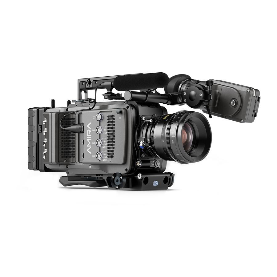
Page 12: Camera Layout
Camera layout Camera layout Right BAT power input RS connector I/O panel Bracket rosette Audio connector panel WPA-1 with quick release connectors Fan intake Fan outlet 12-pin Hirose for ENG type lenses... - Page 13 Camera layout Left Operator panel Media panel (behind lid) User buttons Battery adapter Power button & camera lock Fan intake Audio control panel Recording button Bracket rosette...
- Page 14 Camera layout Viewfinder top buttons Adjustable beam Recording button Camera type label Viewfinder hinge with clamp Level Accessory shoe Accessory threads on camera handle Bottom Battery adapter Viewfinder type label Bracket rosettes WPA-1 quick-lock bracket PLAY button...
- Page 15 Camera layout Front Clamps 15 mm rod receptacles Lens mount (here: PL) RS connector ND filter switch Back Fold-away monitor (viewfinder/GUI) I/O panel OLED eyepiece BAT power input Bluetooth antenna Battery adapter (here: Gold Mount) WiFi antenna Proximity sensor for OLED eyepiece...
-
Page 16: Product Identification
Camera layout Product identification CE type labels with serial number are on the camera top (1) and under the viewfinder (2). An FCC conformity label is on the camera bottom. -
Page 17: Power Supply
Depending on your battery demand, the camera offers either a Gold Mount or a V- Lock adapter. You can change both by yourself (see page 57). For further details, see our website or ask your local ARRI Service Partner. NOTICE For maximum operation time, always use fully charged batteries with 10.5 to 34 V... -
Page 18: Changing A V-Lock Battery
Power supply Changing a V-Lock battery 1. Place the battery's wedge into the V-shaped lock (1). 2. Slide the battery (2) downwards until the adapter audibly locks (1). 3. To release: With the pin pushed (3), slide the battery (2) up- and backwards. BAT in NOTICE If the power supply to BAT is interrupted with the camera switched on, the camera... -
Page 19: Switching On/Off
Switching on/off 1. To switch on: Press the power button (1). 2. The ARRI and AMIRA logos appear in the audio display (2) and monitor (3). 3. To switch off: Press and hold the power button (1). 4. A countdown appears in the audio display, monitor, and viewfinder. -
Page 20: Connectors
Supplies lens servos with power and provides access to lens ser- vo functions. RS (3-pin Fischer) This 3-pin Fischer socket for RS input supplies external acces- sories with 24 V power (2.0 A). It also carries a frame pulse out- put and accepts an ARRI remote start/stop trigger. -
Page 21: Audio Connector Panel
Connectors Audio connector panel NOTICE Rubber caps protect the XLR connectors from dirt and moisture. Always cap unused XLR connectors. Protective caps Headphone out & volume XLR 5-pin audio input XLR 3-pin audio input Input signal options Headphone Headphone 3.5mm stereo TRS (“Mini-jack”) output for monitoring audio channels. - Page 22 Connectors Connecting audio devices 1. Uncap the needed connectors only (1). 2. Connect the headphone (2). 3. Set the headphone volume by turning the wheel (2). 4. Alternatively, you can use the SET wheel on the camera's left. See page 34. 5.
-
Page 23: I/O Panel
Connectors I/O panel NOTICE If the power supply to BAT is interrupted with the camera switched on, the camera will automatically repower and boot-up on reconnection. BAT main power in EXT in/out D-tap Aux power out HD-SDI image out 1 & 2 Return/sync in Timecode in/out 12V (4-pin Hirose) - Page 24 Connectors EXT (6-pin LEMO) A connector for external accessories, carrying two CAN bus- es and accessory power output at camera voltage level (2.0 A max.). BAT (8-pin LEMO) Via cables KC50-S (2 m, straight) and KC50-SP-S (coiled), this main power supply input accepts 10.5 to 34 V DC. SDI OUT 1 &...
-
Page 25: Media Panel
Connectors Media panel Status LEDs CFast 2.0 card slots A & B USB in/out 1 & 2 RJ45 Ethernet Card A & B (CFast 2.0) Storage media slots for CFast 2.0 recording cards. USB 1 & 2 Interface for USB memory sticks with FAT file system. Can also be used to charge USB devices. -
Page 26: Preparing A Usb Memory Stick
Connectors 7.4.1 Preparing a USB memory stick USB memory sticks for the AMIRA must have a specific folder structure which can be created with the camera. 1. To prepare a USB memory stick: Open the media lid (1). 2. Connect a FAT-formatted USB stick (3) to the camera (2). -
Page 27: Changing A Cfast 2.0 Card
NOTICE AMIRA does not accept ALEXA-formatted CFAST 2.0 cards, and vice versa. Before using a CFAST 2.0 card with AMIRA, you must erase it in-camera to create the required file system. Avoid damage to the contacts of both camera and card. Always insert cards as described in this document. -
Page 28: Lens Mount/Filters
- 1.2 - 2.1) ND filter switch NOTICE AMIRA uses FSND (Full Spectrum Neutral Density) filters, which are linear across the full spectrum of the camera sensor. This prevents artifacts from infrared wavelengths and the need for additional IR filters. -
Page 29: Changing A Lens
Lens mount/filters Changing a lens NOTICE The following description applies to PL mounts. For EF and B4 mounts, please refer to the User Manual. Protect the sensor: Always keep a lens or protective cap on the empty lens mount. Change lenses in dry, dust-free environments only. Never exceed the maximum lens dimensions. -
Page 30: Iris Control Via User Button
Lens mount/filters Pressing the wheel (1) changes the step size between full and sub-stops (2). Note: Sub-stop precision depends on the lens type and is automatically set by the camera. On the live screen, you can activate and deactivate iris adjustment (1) by short- pressing the lower round (not oval!) button (2). -
Page 31: Auto Iris
Lens mount/filters 8.3.3 Auto iris HOME > EI > IRIS > OPTIONS Via jogwheel (1), you can define the auto iris behavior. Auto iris mode: Defines the iris calculation: Integral: Iris is calculated based on full image content. • Center: Iris is calculated with higher priority on image center. •... -
Page 32: Audio Control Panel
Audio control panel Audio control panel Audio function switch Audio display Left/right gain controls Audio SET jogwheel Channel configuration NOTICE Audio is disabled if the sensor frame and project rates are not equal. With audio recording disabled or otherwise switched off, neither audio in/output nor audio processing is possible. - Page 33 Audio control panel Adjusting channel gain 1. Select 1/2 or 3/4 (1). 2. Adjust channel 1 (or 3) gain via left gain control (2). 3. Adjust channel 2 (or 4) gain via right gain control (2). 4. To change channel 1/2 (or 3/4) setup: Select the desired parameter via SET jogwheel (3).
-
Page 34: Headphone Volume
Audio control panel Headphone volume Use the headphone volume wheel (see above). Or: Use the audio control panel (see below): 1. Switch to INFO (1). 2. The volume level shows next to the headphone icon in the display. 3. Turn the depressed SET jogwheel (2). -
Page 35: Camera Controls
Camera Controls Camera Controls The camera body offers controls through buttons and switches. 10.1 Operator panel NOTICE The operator panel consists of switches that offer quick changes of important camera functions, such as exposure index or white balance. For all switch positions (except ND positions), you can assign an individual presetting. -
Page 36: Presetting The Us / Ei / Wb Switches
Camera Controls 1. Switch US (1) to the desired position. 2. From the home screen, navigate (1) to MENU > User buttons (4). 3. Via jogwheel (2), select the entry User switch and change it according to your needs: None: User switch is disabled °... -
Page 37: Aw Auto White Balance Button
Camera Controls 7. Confirm by pressing the jogwheel (2). 8. Repeat for other switch positions if desired. 9. For FPS, SHUTTER, LOOK, and WB, you can configure preset lists for each switch position. 10. See the User Manual for detailed instructions. 10.1.3 AW auto white balance button The AW button triggers the auto white balance functionality: Based on the camera's live image, AW calculates an automatic white balance and overwrites the active WB... -
Page 38: Locking/Unlocking
Camera Controls 10.2.1 Locking/unlocking NOTICE Locking the camera disables, unlocking re-enables all camera controls configured for locking except audio controls. Changing the position of the US, EI, WB, or ND switch on a locked camera will result in parameter changes when unlocking. 1. -
Page 39: User Buttons
Camera Controls 10.2.2 User buttons In the camera menu (MENU > User buttons) you can assign individual functions to each user button. For full instructions, see the User Manual. 1. Press a button (1) to trigger its function. 2. For buttons five to eight: Press and hold SHIFT (2); then press a button (1). 3. -
Page 40: Recording
Camera Controls 10.3 Recording NOTICE Pressing a recording button returns the user interface to the home screen and disables the menu access. Recording also disables the US switch and the home screen buttons for FPS, TC, Shutter, and Look settings. 1. -
Page 41: Mvf-1 Controls
MVF-1 controls MVF-1 controls Monitor (Live & GUI) Peaking button Exposure tool button VF1 & VF2 user buttons Monitor button Proximity sensor Diopter control Recording button Screen buttons Jogwheel Proximity sensor This infrared sensor automatically deactivates the viewfinder's internal OLED panel when you withdraw your eye. The sensor is placed either on the bottom left-hand side of the viewfinder (Generation 1, shown in image), or it is integrated in the eye cup (Generation 2, not shown). -
Page 42: Exp Exposure Tool Button
MVF-1 controls 1. To activate peaking on monitor (1) and MVF-1 (3): Press PK (2). 2. Peaking highlights the image parts that are in focus for better focus judgement. 3. For PK settings: Go to MENU > Monitoring > EVF/Monitor > Peaking. 11.2.2 EXP exposure tool button The EXP button (2) activates the set exposure tool on the monitor (1) and EVF image (3). -
Page 43: Vf1 & Vf2 User Buttons
MVF-1 controls 11.2.3 VF1 & VF2 user buttons ► Via the camera menu, you can assign a function to both VF-1 and VF-2 buttons (1). For details, see the user manual. 11.2.4 PLAY button 1. Press PLAY (1) for one second to see the last clip of the active CFast 2.0 card. 2. -
Page 44: Adjusting The Monitor
MVF-1 controls 11.4 Adjusting the monitor ► Fold (1), swivel (2) and flip (3) the monitor according to your needs. 11.5 Changing the monitor mode 1. To change the monitor mode between live view and user interface: Press M (1). - Page 45 MVF-1 controls 2. In live mode, toggle the status bar content (1) via the lower buttons. 3. Via the camera menu, you can activate a location sensor that automatically flips the user interface to match a left- or right-sided monitor position (3). 4.
-
Page 46: Menu Access
MVF-1 controls 11.6 Menu access The user interface centers around the home screen, with access to essential status parameters and camera functionalities: !: Alert messages FPS: Sensor frame rate TC: Timecode SHUTTER: Shutter angle or, if chosen instead, exposure time STBY: Camera standby status WB: White balance LOOK: Gamma settings and look files... -
Page 47: User Monitor
MVF-1 controls Surround mask Exposure index Camera temperature warning (warning=red) 7 White balance ALERT message Shutter value (° or sec) Center mark Sensor frame rate Active ND filter Camera status (here: Standby) Surround mask This grayed-out frame marks all non-recorded parts of the sensor image. -
Page 48: Message Popups
MVF-1 controls White: Sensor temperature warning • Orange: Sensor temperature critical or System • temperature warning Red: System temperature error • (see INFO > System info) Fan icon Icon color shows the fan noise status: Grey: About to increase above 20 dB(A). •... -
Page 49: Overlay Menu
Exit the overlay menu by pressing the user button. Transvideo StarliteHD5-ARRI The Transvideo Starlite HD5-ARRI monitor (K2.0006960) is a 5" 3G-SDI Oled monitor with an integrated H.264 recorder, a touchscreen and a special ARRI bus interface to communicate with the camera. - Page 50 Connect the bus interface cable to the EXT port of the camera. Activate the overlay menu by pressing the "ARRI" touch icon on the monitor. Select a parameter with arrow icons of the monitor.
-
Page 51: Web Remote
Web remote Web remote AMIRA has a web remote function for full remote control of the camera with a web browser (tested with: Google Chrome 39 and Mozilla Firefox 34). It requires a connection to the camera via WiFi or with a RJ-45 LAN cable. - Page 52 Web remote REC INFO: Contains info on the main recording relevant parameters, plus a REC button. Click the big circle icon to start/stop recording. Note: Rec status may respond with a little delay depending on network speed. USER: Shows configuration of user buttons and allows to trigger them. Press number icons to trigger user buttons.
-
Page 53: Camera Preparation
Camera preparation Camera preparation 14.1 Adjusting the viewfinder 1. Slightly loosen the clamp (1) to move the viewfinder (2) left/right and up/down. 2. Unclamp the hinge (3) to swivel the viewfinder horizontally. 3. Close all clamps (1, 3) when the viewfinder is in the desired position (2). -
Page 54: Balancing The Camera Weight
Camera preparation 14.2 Balancing the camera weight 1. Unlock (4) and slide the base adapter (3) until the camera is balanced. 2. Close the clamp (4). 3. Unclock (1) and slide the handle (2) until the camera is balanced. 4. Close the clamp (1). -
Page 55: Mounting To A Wedge Plate
Camera preparation 14.3 Mounting to a wedge plate 1. For mounting to a wedge plate, use the WPA-1 wedge plate adapter. 2. Open the quick-release base plate. 3. Place the adapter (1) into the quick-lock plate slighty behind the connection points. 4. -
Page 56: Mounting To A Bridge Plate
Camera preparation 14.4 Mounting to a bridge plate NOTICE Always use a flat screwdriver to connect the BPA-3 to a bridge plate. Never use a coin. A coin does not deliver enough force to ensure a proper lock. 1. For mounting to a bridge plate, use the BPA-3 bridge plate adapter. 2. -
Page 57: Assembly And Retrofits
Assembly and retrofits Assembly and retrofits NOTICE To avoid damage while assembling and retrofitting, always place the camera on a padded, firm, flat and level surface. Work on an unpowered camera only. 15.1 Battery adapter Tools needed 2.5 mm Allen key •... - Page 58 Assembly and retrofits Unmounting 1. Note: The illustration shows a Gold Mount adapter. 2. Switch off; interrupt the power supply. 3. With a 2.5 mm Allen key, unfasten all three screws (2). 4. Remove the battery adapter (1).
-
Page 59: Base Adapter
Assembly and retrofits 15.2 Base adapter Mounting 1. Note: The illustration shows a WPA-1. 2. Open the clamp (1). 3. Slide the adapter under the camera (3). 4. Note: The safety pin (2) must audibly lock. 5. Close the clamp (1). - Page 60 Assembly and retrofits Unmounting 1. Note: The illustration shows a BPA-3. 2. Open the clamp (1). 3. With the safety pin pulled (2), slide the adapter off the camera (3).
-
Page 61: Camera Handle
Assembly and retrofits 15.3 Camera handle 1. Open the clamp (1). 2. Slide the handle onto the camera (2). 3. Note: The safety pin (3) must audibly lock. 4. Close the clamp (1). 5. To unmount: Open the clamp (1). 6. -
Page 62: Viewfinder And Evf Cable
15.4 Viewfinder and EVF cable Tools needed 2 mm Allen key • EVF port Via original AMIRA EVF cable, this port connects the camera to the multi-viewfinder. Changing the EVF cable 1. Note: Use original AMIRA EVF cables only. 2. Place the camera bottom-down. - Page 63 Changing the viewfinder 1. Switch off; interrupt the power supply. 2. Note: Use original AMIRA EVF cables only. 3. Connect a EVF cable to the camera. See page 62. 4. With your fingers, unscrew and remove the viewfinder’s lid (1).
- Page 64 Assembly and retrofits 8. Open the clamp (1). 9. Either: Dovetail the viewfinder to the bracket (2). 10. Or: Unbracket (2) and remove the viewfinder. 11. Close the clamp (1).
-
Page 65: Antennas
Assembly and retrofits 15.5 Antennas 1. With your fingers, thread the antennas for WiFi (1) and Bluetooth (2) onto the camera. 2. To unmount: Unthread the antennas (1, 2) with your fingers. WiFi Antenna for WiFi signal according 802.11g. Used for remote camera access. -
Page 66: Licensing And Updating
16.2 Licensing You can further enhance the camera capabilities through licensed features available for online purchase. Visit the ARRI license shop at http://alshop.arri.de and follow the instructions for purchasing and downloading license keys. License keys are linked to each camera's serial number and cannot be transferred from one camera to another. -
Page 67: License Bundles
Licensing and updating 16.2.1 License bundles To view the features contained in the active license bundle, press FEATURES screen button (1). Temporary licenses Licenses are also available as temporary real-time licenses. After installation, the license is valid for a defined period past the installation time. After this period, the license becomes invalid. -
Page 68: Appendix
Height 149 mm Width 139 mm Weight 4.1 kg / 9 lbs (camera body with PL mount) Sensor 35 mm format ARRI ALEV III CMOS with Bayer pattern color filter array Sensor photo HD 16:9 2880x1620 sites 2K 16:9 2867x1613 3.2K 16:9... - Page 69 Appendix Titanium PL mount with L-Bus connec- tor and LDS (Note: LBUS motors are not supported by AMIRA) EF mount PL mount with Hirose con- nector and LDS B4 mount with Hirose connector Recording media CFast 2.0 memory cards Sound level <...
- Page 70 Appendix 3.2K 16:9 ProRes 422 LT ProRes 422 ProRes 422 HQ ProRes 4444 ProRes 4444 XQ 4K UHD 16:9 ProRes 422 LT ProRes 422 ProRes 422 HQ ProRes 4444 ProRes 4444 XQ Electrical data DC power input 10.5 to 34 V DC power output 10.5 to 12 V (RS: 24 V) / 2.0 A Operation temperature...
- Page 71 Appendix Input clipping indication through red frame around audio meter Internal test tone generator 1 kHz sine @ -9 dBFS / -18 dBFS / -20 dBFS...
-
Page 72: Dimensional Drawings
WHICH LICENSE IS AVAILABLE FROM MPEG LA; LLC; 4600S. ULSTER ST., SUITE 400, DENVER, CO 80237. 17.4 Declarations of conformity EC Declaration of Conformity The product AMIRA 1 conforms with the specifications of following European directives: Directive 2014/30/EU Community directive for the adaptation of legal •... - Page 73 Appendix WLAN: FCC ID: PD962205ANH • Bluetooth: FCC ID: QOQWT32AE • Industry Canada Compliance Statement Complies with the Canadian ICES-003 Class A specifications. Cet appareil numérique de la Classe A est conforme à la norme NMB-003 du Canada. This device complies with RSS-210 of Industry Canada. Cet appareil est conforme à...
- Page 74 AMIRA CAMERA DIMENSIONS – Version 2015-01 Technical Data are subject to change without notice. Camera Right Camera Front Image Plane Optical Center 213 mm 73 mm 268 mm min. max. max. 8.12” 4.06” 9.1” 173 mm 144 mm max. min.
- Page 75 AMIRA CAMERA DIMENSIONS – Version 2015-01 Technical Data are subject to change without notice. Camera Left Camera Back Image Plane Optical Center 46 mm 102 mm 36 mm 1.83” 4.00” 1.42” UNC 3/8“–16 (10 mm deep) UNC 3/8“–16 (10 mm deep)
- Page 76 AMIRA CAMERA DIMENSIONS – Version 2015-01 Technical Data are subject to change without notice. Camera Top Camera Bottom Image Plane Image Plane 173 mm 6.81” 20 mm 80 mm 60 mm 25.4 mm 25.4 mm 25.4 mm 25.4 mm 23 mm 1,0”...
Need help?
Do you have a question about the Amira and is the answer not in the manual?
Questions and answers