Table of Contents
Advertisement
Ref: ST471Z01_R-_GB
ST471Z50
ST471Z53
l
SOCIÉTÉ DES ANCIENS ÉTABLISSEMENTS
GEISMAR
L.
113 bis, Avenue Charles-de-Gaulle
Neuilly sur Seine
92200
- France
•Tel.: +33 (0)1 41 43 40 40
•Fax: +33 (0)1 46 40 71 70
•
E-mail : geismar@geismar.com
C)
CIO
SOCIÉTÉ TURRIPINOISE
DE MECANIQUE
5, Rue de d' Altkirch
Route d'Italie - BP 57
Colmar
68 006
cedex - France
38352 La Tour du Pin cedex - France
•Tel.: +33 (0)3 89 80 22 11
•Tel.: +33 (0)4 74 97 24 88
•Fax: +33 (0)3 89 79 78 45
•Fax: +33 (0)4 74 97 30 76
•E-mail: colmar@geismar. c om
•
E-mail : stumec@geismar.com
Anglais - Translation from the original
·-
SECTION
GRINDER
MP.12
www. geismar. com
MP.12
instruction manual
Type
Advertisement
Table of Contents

Related Manuals for GEISMAR STUMEC MP.12

Summary of Contents for GEISMAR STUMEC MP.12
- Page 1 MP.12 Ref: ST471Z01_R-_GB ST471Z50 Anglais - Translation from the original ST471Z53 instruction manual ·- SECTION GRINDER Type MP.12 SOCIÉTÉ DES ANCIENS ÉTABLISSEMENTS SOCIÉTÉ TURRIPINOISE GEISMAR DE MECANIQUE 113 bis, Avenue Charles-de-Gaulle 5, Rue de d' Altkirch Route d'Italie - BP 57...
- Page 2 GEISMAR, the quality choice ! You have just acquired a machine for laying and servicing railway lines. We thank you for choosing equipment developed and constructed by GEISMAR / STUMEC, the fruit of over eighty years’ experience. Every day since 1924, the GEISMAR Group has been investing in research and state-of-the-art construction to offer you the quality and reliability so essential to the requirements of the world of railways.
-
Page 3: Table Of Contents
Safety and general usage recommendations grooved rollers) General safety instructions Taking the machine off the track Specific safety recommendations Storage 1.4.1 Risks that may arise through use of the "MP.12"- 4.5.1 General storage recommendations type grinder 4.5.2 Specific storage recommendations 1.4.2 Safety rules to be observed before and during use of the "MP.12"-type grinder... -
Page 4: Chapter 1 - Safety
CHAPTER 1 – SAFETY 1.1 Foreword The following set of rules has been drawn up to ensure the application of precautionary principles that help to preserve the safety of persons and property when the machine is in use. Any failure to comply with these rules can have serious repercussions (bodily injury, etc.), and can even be fatal, so we must draw your attention to the fact that all persons involved in the use, maintenance, storage or custody of the machine covered by the present manual must be familiar with these rules. -
Page 5: General Safety Instructions
1.3 General safety instructions • The operator and the working environment To avoid all risks of accident or injury, it is essential to wear: - Sturdy, non-flammable clothing that is suitably close-fitting - Strong, non-slip gloves - Safety shoes - Protective eyewear - Safety helmet - All other equipment necessary on the site or when using the machine In the case of use of ear defenders, the safety instructions in force on the site must be complied with at all times. - Page 6 • The operator and the machine Before putting the machine into service each time, check that its condition and its operation are in compliance with the instructions. In particular, make sure that the controls are free and in good working order, and that they are in the “stop” or “neutral” position. Never make any modifications that could affect correct operation of the control systems.
- Page 7 • Using and handling fuel and oil It is essential to stop the engine and set the control to the stop position before carrying out any work involving fuel (filling up, checking the level, draining, etc.). Always keep suitable extinguishers ready for use in all areas where fuel is handled (storage, filling up, etc.). Always store fuel and oil in separate cans specially designed for the purpose and bearing the labels required by regulations.
- Page 8 • Tools to be used on the machine Use only the types of tools intended for normal use of the machine. Measure the speed of all rotating tools at regular intervals. Never use tools at speeds greater than the maximum speed for which they have been designed and approved. Never use damaged tools or tools that have reached their maximum level of wear.
-
Page 9: Specific Safety Recommendations
1.4 Specific safety recommendations 1.4.1 Risks that may arise through use of the "MP.12"-type grinder The main risks for the user and those around that arise when using the "MP.12"-type rail grinder are: Fire connected with fuel handling. Fire caused by the sparks coming into contact with inflammable material. -
Page 10: Safety Rules To Be Observed Before And During Use
1.4.2 Safety rules to be observed before and during use of the "MP.12"-type grinder All personnel using this equipment must wear the clothing listed in paragraph §1.3 "General safety instructions / The operator and his environment" masks or goggles, helmet, smock, fire-proof gaiters or boots. -
Page 11: Personal Protective Equipment
1.4.3 Personal protective equipment • All personnel using this equipment must wear the clothing listed in paragraph §1.3 "General safety instructions / The operator and his environment". They must also wear anti-spark protection, such as: mask or goggles, smock and non-slip sturdy gloves, fire-resistant gaiters or boots. •... -
Page 12: Safety Symbols And Recommendations
1.4.4 Safety symbols and recommendations The safety pictograms and recommendations must be present on the grinder at the indicated location. If one of them is missing or has deteriorated, another must be ordered immediately and installed in its place. If a component bearing a label has been replaced, make sure a new label is placed on the replacement part. Reference: N°... -
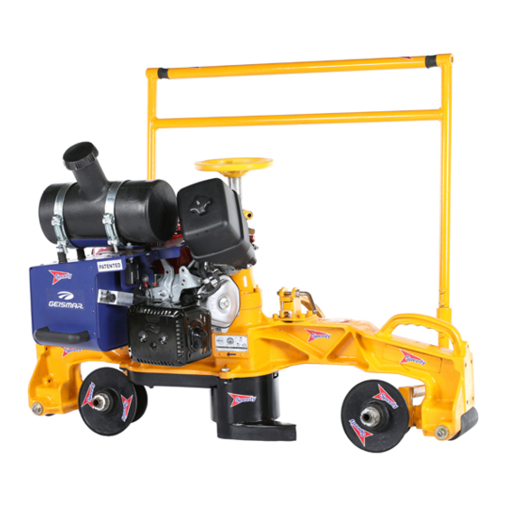
Page 13: Chapter 2 - Description Of The Machine
Type MP.12 The MP.12 section grinder is designed for grinding railheads and welds, including the curves and sides. Its exceptional performance and durability, due to its rigid and non-deformable alloy chassis, provide the operator with optimum ease of use. The guiding rollers and broad wheelbase guarantee consistency of grinding from the horizontal to the vertical. -
Page 14: Overview
2.2 Overview Ref. Description Manoeuvring handle Grinding wheel adjusting assembly Engine shutdown Engine Carrying handle (x2) Guide roller Grinding wheel housing Stop lug Manoeuvring lever lock handle Grinding wheel descent blocking handle Crutch anti tilt Engine cut Hour meter Engine pressure gauge Do not exceed 1.5 bar Fuel tank To simplify machine identification, when ordering spare parts, please specify their type and number,... -
Page 15: Technical Characteristics
2.3 Technical characteristics ENGINE TYPE MP.12 Engine Robin DY27-2D Machine dimensions ---/---/--- Length / width / height Masses Machine (no load) Machine (in working order) Noise Acoustic pressure level (La dB (A) (±2) Acoustic power level (Lwa) dB (A) (±2) - Page 16 2.5 Machine location inside the clearance gauge The diagram below shows the dimensions of the machine as compared with the lower UIC 505-1 clearance gauge (track with a nominal gauge of 1.435 m). 9450 mm 9800 mm 1220 mm MP12_Fr_01596_160222...
-
Page 17: Chapter 3 - Installation - Starting
CHAPTER 3 – INSTALLATION – STARTING 3.1 Installing the grinding wheel The grinding wheel must be installed with the engine off and the machine on the ground. To install the grinding wheel, proceed as follows: Disassembling the grinding wheel: 1 → Lower the grinding wheel as far as possible, then remove the grinding wheel housing ② by removing the 2 bolts ① (17 spanner) (see fig.1). 2 →... -
Page 18: Placing The Machine On The Track
3.2 Placing the machine on the track At least two people must be involved when placing the machine on or taking it off track. Nonetheless, if the work area is difficult to access, more people may be required to ensure safe handling operations. •... -
Page 19: Guide Roller Settings
3.3 Guide roller settings The guide roller separation is adjustable, so the machine can be placed on all types of rail, regardless of the width of the railhead. 3.3.1 Settings for flat-bottomed rails Adjust one of the two guide rollers, as follows: •... -
Page 20: Fuel
3.4 Fuel - The rail grinder’s engine must use of Gas-oil - Motor oil use 4-stroke motor oil that meets or exceeds the engine recommendations. Filling up with fuel - Storing the Gas-oil Empty the fuel tank and run the engine until it stops after each use of the machine. Be careful when opening the fuel can. -
Page 21: Inspecting The Machine
3.5 Inspecting the machine Each component of the machine must be inspected by a qualified person prior to commissioning in order to detect any defects. The inspection is mainly a visual and operational check. The inspection phase ensures the different components are in good condition and have not been damaged during transport or storage. •... -
Page 22: Chapter 4 - Use
CHAPTER 4 – USE 4.1 Conditions of use 4.1.1 Operator work area The operator's work area is between the two rails on a single string. This WORK AREA work area ensures the operator can work under optimum safety conditions. The operator must (where possible) always remain within this area. If the work to be carried out requires positioning outside this area, make sure it is safe, above all if the work is carried out without stoppage of traffic. -
Page 23: Starting And Stopping The Machine
4.2 Starting and stopping the machine Refer to the engine manufacturer’s guide to determine the location of the components to activate when starting and stopping. THE MACHINE MUST ONLY BE STARTED WHEN IT IS ON THE TRACK Mise en marche: •... -
Page 24: Operating The Machine
4.3 Operating the machine 4.3.1 Use on flat-bottomed rails Move the machine on the rail using the two flat rollers, keeping the guide flanges horizontal on either side of the rail (See §3.3 “ Guide roller settings” • Start the engine (see engine guide and §4.2 “Starting and stopping the machine”). -
Page 25: Use On Grooved Rails
4.3.2 Use on grooved rails (if the machine is equipped with grooved rollers) Move the machine on the rail using the two flat rollers, keeping the guide flanges horizontal and centred in the groove (See §3.3 “Guide roller settings”). • Start the engine (see engine guide and §4.2 “Starting and stopping the machine”). -
Page 26: Taking The Machine Off The Track
Take the machine off the track by following §3.2 “Placing the machine on the track” in reverse order. As indicated in the same paragraph, the MP.12-type section grinder can be placed on/taken off the track by two people. Nonetheless, if the work area is difficult to access, more people may be required to ensure safe handling operations. -
Page 27: Storage
4.5 Storage 4.5.1 General storage recommendations During periods where the equipment is not in use, it is indispensible to store it properly in order to keep it in good working order. Poorly-stocked equipment may deteriorate when recommissioned. It is also important for the personnel responsible for storage operations to take great care during storage, and to carefully follow the recommendations. -
Page 28: Specific Storage Recommendations
4.5.2 Specific storage recommendations For extended storage of the machine, empty the fuel tank. Never store the machine with the grinding wheel mounted. Store the grinding wheels in a dry place, protected from frost, sunlight and heat. Arrange them so they are not under stress to avoid deformation. The equipment must not be stored for more than 2 years. -
Page 29: Chapter 5 - Servicing / Maintenance
17 open-ended spanner (Ref. FJM) For 600Y grinding wheel mount: Spark plug spanner (Ref. GGK) Pin (Ref. 16761) MP.12 - BRIGGS & STRATTON 13 x 23 open-ended spanner (Ref. GAW) For 37042 and 37006 wheel plate: 122672 Hook spanner (Ref. 37088) 13 open-ended spanner (Ref. -
Page 30: Engine
5.1.2 Engine Strictly comply with the manufacturer’s instructions. SEASON OR GRADE FILLING ENGINE OIL OF OIL TEMPERATUR - Place the engine horizontally and pour oil up to the upper level Spring or Summer or Autumn SAE30 104°F (40 "C ) to +50°F (10°C ) of the oil gauge (approx. -
Page 31: Drive Belt Tension
5.1.5 Drive belt tension (the engine must be off) The drive belt is tensioned by variation of the pitch diameter of the pulleys through a clamp set. The drive pulley and the receiving pulley are both adjustable. To access the pulleys, dismount the grinding wheel, the grinding wheel housing and the belt housing. Every 50 hours of operation, check the belt tension and adjust it if necessary as follows: Dismantle the pulley flange ①... -
Page 32: Filtering
To guarantee proper alignment of the drive belt, you must carry out the same adjustment on each of the pulleys. When there are no more clamps between the flanges of the two pulleys and the belt is slipping, a new belt must be installed in its place. To install a new belt, put all of the clamps (12 per pulley) between the pulley flanges. -
Page 33: Engine Rotation Speed
5.1.7 Engine rotation speed When shipped from the factory, the carburettor is delivered with the optimal adjustment corresponding to the pressure and climate conditions of the factory. For optimum use of the machine, the engine must have an engine speed corresponding to that indicated in §2.3 “Technical characteristics”. Apart from standard maintenance during use, it is recommended that you have GEISMAR sales or breakdown repair agents carry out repairs or adjustments to the carburettor. -
Page 34: Maintenance
5.2 Maintenance 5.2.1 Preventive maintenance calendar FREQUENCY When there Every Every COMPONENTS TYPE OF OPERATION Before After Every are obvious each use each use week signs of wear hours hours or malfunction Entire machine Chap.3 - § 8 Inspecting the machine Perform general cleaning with a clean... - Page 35 5.2.2 List of normal wear parts (this list does not include motor parts) This is a list of normal wear parts on the machine together with the conditions under which they should be replaced. Nevertheless, any part that is worn, damaged or missing must be changed or repaired immediately, whenever there is a risk in terms of safety. Description Replacement conditions 35 –...
-
Page 36: Chapter 6 - Accessories And Options
CHAPTER 6 – ACCESSORIES AND OPTIONS 6.1 Optional equipment 6.1.1 Power take-off There must be two operators to use the grinding hose on machines equipped with power take-off. The engine must be turned off prior to work on the grinding wheel or hose. Installing the hose: After making sure the fuel tank is not too full, to avoid fuel leaks, (if applicable) reinstall the grinding wheel so it is hidden as much as possible within the protective cover. -
Page 37: Handle
Power take-off device (ref. 37000 DS – original component supplement) Hoses (for use with grinding wheel holders) Hose without clutch: − Length 3 m (ref. 16300 A); − Length 4 m (ref. 16300 B); Hose with clutch (Mandatory for EC machines equipped with power-take-off device): −... -
Page 38: Balancing Bar
1372-track balancing bar (ref. 37054 J) 6.1.5 Palm stop button 6.1.6 Manoeuvring lever (anti-vibration and height-adjustable) Palm stop button for all MP.12 and MOD.12 models (ref. 12000 EZ) Anti-vibration manoeuvring lever (ref. 37380) Anti-vibration manoeuvring lever (ref. 37381) Anti-vibration manoeuvring lever (ref. 37000 GF) Height-adjustable manoeuvring lever (ref. -
Page 39: Limit Of Grinding Wheel Descent
6.1.8 Limit of grinding wheel descent Grinding wheel descent limiter (ref. 37000 JZ) 6.1.9 Adaptation kit for harmonic grinding Harmonic wear grinding to convert a MP12 into a MOD12 with balancing bar (Ref. 37000 BH and 37000 K) 6.1.10 Adaptation kit for grooved rail grinding The machine must be equipped with a Ø... - Page 40 CHAPTER 7 – SPARE PARTS CATALOG 7.1 Drawings and parts lists CH7_Gb_00032_070529.doc...
- Page 41 IMPORTANT Afin que votre commande de pièces de rechange soit suivie d’une livraison prompte et correcte, bien indiquer : Le rep., le nombre et la désignation des pièces de rechange - Le type et le n° de série de la machine (plaque sur le châssis) ********************************************************************* IMPORTANT To ensure that you are delivered promptly and correctly after placing an order for...
- Page 42 Tableau d'équivalence - codes machine / plans Table of equivalence - machine codes / plans MP12 MP12 MP12 sans mot. sans mot. sans mot. ST471Z01 ST471Z50 ST471Z53 37000 AP 37000 AQ 37000 KH 37000 KJ...
- Page 44 37 000 KH - KJ RAIL PROFILE GRINGING MACHINE - Model MP.12 (1/2) (R-) (R1) Ref. Description Ref. Description 8 057 Tightening cap 37 032 Grindstone feed-screw 11 063 Hand-lever of feedwheel brake 37 033 Grindstone feed-nut 16 356 Grindstone axle 5/8 WW...
- Page 45 37 000 KH - KJ RAIL PROFILE GRINGING MACHINE - Model MP.12 (R-) (R1) (2/2) Ref. Description Ref. Description Screw Chc 8 x 20 Polyamide knob dia. 40 Screw H 6 x 15 Thrust ball bearing n° 51104 Circlips 40 e Ball bearing n°...
- Page 48 RAIL PROFILE GRINDING MACHINE Model MP.12 37 000 AP - 2 - Runner Assy, each including : Ref. Description Ref. Description 5 110 Washer DIA 10,5 x 30 x 5 Circlips 47 i 37 021 Runner-axle Nylstop nut of 10...
Need help?
Do you have a question about the MP.12 and is the answer not in the manual?
Questions and answers