
Related Manuals for Kipor KGE2500X


Summary of Contents for Kipor KGE2500X
- Page 1 OPEN-FRAME GASOLINE GENERATING SET SINGLE-PHASE: KGE2500X KGE4000X KGE6500X/E THREE-PHASE: KGE6500X3/E3 WELDING & GENERATING SET: KGE6500XW/EW...
-
Page 2: Table Of Contents
1. SAFETY INFORMATION CONTENTS In order to operate this generating set safely and reliably, please follow the below requirements. 1. Safety information 1-1 Do operate it at well ventilated place, for the exhaust contains poisonous carbon monoxide. Do not operate it at unventilated place! (see fig.1) 2. -
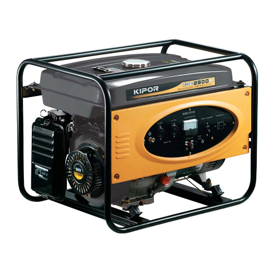
Page 3: Identification Of Components
2. IDENTIFICATION OF COMPONENTS 3. PRE-OPERATION CHECKS Be sure to perform the following checks before starting the generating set. 3-1 Check whether the generating set is on a level surface. 3-2 Check the level of engine oil (1) Take out the oil filler cap and clean the measure mark with a clean rag. (see fig.8) (2) Insert the oil filler cap without rotating it. -
Page 4: Starting The Generating Set
3-4 Check the air cleaner 4. STARTING THE GENERATING SET (1) Remove the clip and dismount the case of air cleaner. Loose the nut and re- move the cover of air cleaner. (1) Disconnect any load from AC (2) Set the fuel oil valve to receptacleand switch off AC breaker. -
Page 5: Usage Of The Generating Set
5-2 Application of AC 5. USAGE OF THE GENERATING SET 1. Starting the generating set 5-1 In order to keep the generating set in best mechanical and electrical condition, please follow the blow items. (1) Please ground the grounding terminal of the set to prevent any false operating. -
Page 6: Stopping The Generating Set
5-3 Electrical apparatus particularly motor-driven equipment will produce 6. STOPPING THE GENERATING SET very high current while starting, the below table provides the reference for connecting these apparatus to the set. 6-1 Switch off the AC breaker 6-2 Switch off the engine switch (X Type) (E Type) 6-3 Close the fuel valve... -
Page 7: Maintenance
Use SE, SF engine oil classified by API (1) Shorten maintenance intervals if the generating set operated in dirty area. or SAE5W-30 engine oil which same as (2) The above-mentioned items must be performed with the assistance of KIPOR SG grade when the temperature is dealer. - Page 8 7-2 Air cleaner (see 3-4) 7-4 Maintenance of the fuel filter 7-3 Spark plug (1).Set the fuel valve on OFF position and dismount the fuel strainer cup. Dismount the fuel filter Blow it from the opposite direction of the arrow 1.
-
Page 9: Storage
8. STORAGE 9. TROUBLESHOOTING 1. Remove the drain screw plug and 2. Remove the filler cap and drain 1. The generating set cannot start. 2. Whether the engine switch is in drain out gasoline from the carburetor. screw plug, then drain off the OFF position? engine oil. -
Page 10: Main Technical Specifications And Data
10. MAIN TECHNICAL SPECIFICATIONS AND DATA Model KGE6500E3 KGE6500X3 Item 10-1 Technical specifications and data of single-phase generating set Model KG390 Type 4-stroke, OHV KGE6500X KGE2500X KGE4000 KGE6500E Displacement (cm ) Model KG200 KG270 KG390 Bore x stroke (cm) 88X64 Type... - Page 11 10-3 Technical specifications and data of welding&generating set Explanation of three-phase generating set: (1) Connect the loads to the generating set in order. As for the motor loads, start Model the higher power motor first, and then start the lower after the former started. Be KGE6500EW KGE6500XW Item...
- Page 12 Explanation of welding&generating set: Parallel operation of two sets: When the users have to weld much thicker steel plate, the maximum welding current of single set won't be sufficient, then the Prepare the required welding cable and connect it to the generating set users can connect two sets in parallel, as the result, the larger welding current will terminals.
-
Page 13: Description Of Accumulator Unit
11. DESCRIPTION OF ACCUMULATOR UNIT 12. DESCRIPTION OF CASTOR UNIT 1. Fix the four castors on the axles with washer and pin. 1. Assemble the accumulator unit with bolt, nut, and washer. 2. Connect the electric starting cable to the starting electromagnet, by crossing 2. -
Page 14: Wiring Diagram
13-2 Electric skeleton diagram of KGE6500X 13. WIRING DIAGRAM 13-1 Wiring diagram of single-phase generating set (X model) Rotating winding Secondary winding Description Parts No. Fuse ON-OFF relations of control switch Fuse Main winding Sampling winding Low pressure winding Secondary winding Description Parts No. - Page 15 13-3 Electric skeleton diagram of KGE6500E 13-4 Wiring skeleton diagram of KGE6500X3 ON-OFF relations of control switch Description Parts No. ON-OFF relations of control switch Description Parts No. Stabilibvolt regulator Fuse Fuse Fuse Fuse Main winding Accumulator Sampling winding Description Main winding Parts No.
- Page 16 13-5 Electric skeleton diagram of KGE6500E3 13-6 Electric skeleton diagram of KGE6500XW/KGE6500EW Description Description Parts No. Parts No. Current inducing modular OLSW Low oil level switch SUTO Auto switch Resistance Capacitance Adjustable resistance Fuse Spark plug Accumulator Select switch ON-OFF relations of control switch Description Parts No.
-
Page 17: Appendix
14. APPENDIX QUANTITY NAME REMARK Generator Number of control Electric plug receptacle box socket NAME QUANTITY REMARK Gasoline generator set operation manual Gasoline engine operation manual Gasoline engine parts diagram Certificate of quality Packing list...
Need help?
Do you have a question about the KGE2500X and is the answer not in the manual?
Questions and answers