Table of Contents
Advertisement
7 1
7 1
series
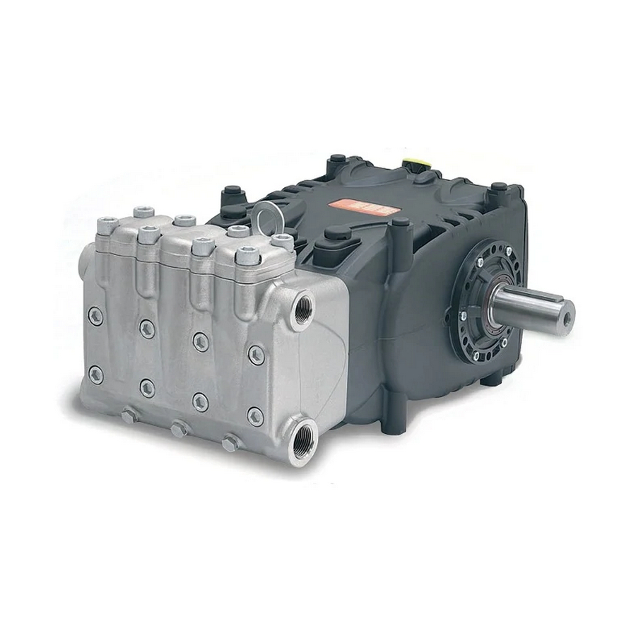
Pump type
Flow rate
Type de pompe
Débit
Pumpentype
Förderleistung
Tipo de bomba
Caudal
Tipo di pompa
Portata
l/min.
WK355
57
Max. pressure
r.p.m.
Pression
tr./min.
Druck
u.p.m.
Presión
r/min.
Pressione
g./min.
G.P.M.
bar
MPa
p.s.i.
(U.S.A.)
15.1
1000
350
35
5075
53
Power
Weight
Dimensions
Puissance
Poids
Dimensions
Leistung
Gewicht
Dimension
Potencia
Peso
Dimensiones
Potenza
Peso
Dimensioni
kW
hp
kg
63
38,10 51,8
507x367x210
mm
Advertisement
Table of Contents

Related Manuals for Interpump 71 Series


Summary of Contents for Interpump 71 Series
- Page 1 series Pump type Flow rate Max. pressure r.p.m. Power Weight Dimensions Type de pompe Débit Pression tr./min. Puissance Poids Dimensions Pumpentype Förderleistung Druck u.p.m. Leistung Gewicht Dimension Tipo de bomba Caudal Presión r/min. Potencia Peso Dimensiones Tipo di pompa Portata Pressione g./min.
-
Page 2: Table Of Contents
Table of Contents 1 INTRODUCTION ..................................22 2 DESCRIPTION OF SYMBOLS ..............................22 3 SAFETY ....................................22 3.1 General safety warnings .................................. 22 3.2 Essential safety in the high pressure system ..........................22 3.3 Safety during work .................................... 22 3.4 Rules of conduct for the use of lances............................22 3.5 Safety during system maintenance ............................. -
Page 3: Introduction
Safety during work Proper pump operation and duration depend on the correct use and maintenance. Interpump Group disclaims any responsibility for damage caused by negligence or failure to observe the standards The room or area within which the high pressure system described in this manual. -
Page 4: Safety During System Maintenance
9. The high pressure system must not be started up and run PUMP IDENTIFICATION under pressure without all team members in position and Each pump has its own Serial No. XX.XXX.XXX see pos. without the Operator having already directed his/her lance an identi cation label, see pos. ... -
Page 5: Dimensions And Weight
DIMENSIONS AND WEIGHT For Standard Version pump dimensions and weight, refer to Fig. 2. For type "A" Flange Version pump dimensions and weight, refer to Fig. 2/a. Fig. 2 Dry weight 60 kg. Fig. 2/a Dry weight 61 kg. Sound emission OPERATING INSTRUCTIONS The sound pressure detection test was performed according The HF pump has been designed to operate in to Directive 2000/14 of the European Parliament and Council environments with atmospheres that are not... -
Page 6: Brands And Types Of Oils Recommended
Check the oil level and top up if necessary Brands and types of oils recommended Using the oil dipstick pos. , Fig. 3. The pump is supplied with oil suitable for room temperatures The correct checking of the oil level is made with the pump from 0°C to 30°C. -
Page 7: Ports And Connections
Viscosity / Room Temperature diagram /s = cSt Ambient temp. (°C) The used oil must be placed in a suitable container and disposed of in special centres. It absolutely should not be discarded into the environment. PORTS AND CONNECTIONS The HF series pumps (see Fig. 4) are equipped with: 2 “IN“... -
Page 8: Pump Installation
PUMP INSTALLATION Version change The pump version is de ned as right when: Installation Observing the pump facing the head side, the pump shaft The pump must be xed horizontally using the M16x1.5 must have a PTO shank on the right side. threaded support feet. -
Page 9: Suction Line
5. Do not use 3 or 4-way hydraulic ttings, adapters, swivel Suction line joints, etc. as they could jeopardise pump performance. For a smooth operation of the pump, the suction line should 6. Do not install Venturi tubes or injectors for detergent have the following characteristics: suction. -
Page 10: Outlet Line
The lter must be installed as close as possible to the pump, Calculation of the internal diameter of the it must be easily inspected and must have the following duct pipes characteristics: To determine the internal diameter of the duct, refer to the 1. -
Page 11: V-Belt Transmission
9.10 V-belt transmission The pump can be controlled by a V-belt system. For this pump model, we recommend use of 4 XPB belts (16.5x13 serrated). Use an XPC pro le only for long durations. Both the characteristics and transmissible power of each belt can be veri ed in the diagram in Fig. 7, in relation to the number of rpm normally declared by the manufacturer. - Page 12 Dimensions (in mm) Belt section as per DIN symbol XPB/SPB XPC/SPC DIN 7753 part 1 and B.S. 3790 symbol B.S./ISO Belt section as per DIN symbol DIN 2215 and B.S. 3790 symbol B.S./ISO Pitch width 14.0 19.0 α = 34° 18.9 26.3 Increased grooving width b ≈...
-
Page 13: De Nition Of Static Pull To Apply On Belts
. Unless otherwise stated by the supplier of the belts, 9.12 De nition of static pull to apply on belts Note control of proper pull and its relative re-tensioning should be Static pull depends on: performed after no less than 30 minutes of motion necessary a) The wheelbase between the two pulleys (belt length). -
Page 14: Start-Up And Operation
START-UP AND OPERATION PREVENTIVE MAINTENANCE For pump reliability and e ciency, comply with maintenance 10.1 Preliminary checks intervals as shown in the table of Fig. 15. Before start-up, ensure that: The suction line is connected and pressurised PREVENTIVE MAINTENANCE (see par. 9.4 - 9.5 - 9.6) the pump must never run Every 500 hours Every 1000 hours dry. -
Page 15: Guarantee Conditions
Safety devices are decalibrated or disconnected. d) The pump is used with accessories or parts not supplied Vibrations and shock to pipes: Air suction. by Interpump Group. Imperfect functioning of the pressure control e) Damage has been caused by: valve. -
Page 16: Exploded Drawing And Parts List
EXPLODED DRAWING AND PARTS LIST... - Page 18 ENGLISH...
-
Page 20: Flushing Circuit Diagram Of Use
FLUSHING CIRCUIT DIAGRAM OF USE Adhere to the following values for proper system operation: minimum circuit ow rate 4 l/min, maximum uid pressure 6 bar. Pump head Pump casing... -
Page 21: Declaration Of Incorporation
DECLARATION OF INCORPORATION (In accordance with Annex II of European Directive 2006/42/EC) The manufacturer INTERPUMP GROUP S.p.A. - Via E. Fermi, 25 - 42049 - S. ILARIO D'ENZA - Italy DECLARES that the product identi ed and described as follows:...
Need help?
Do you have a question about the 71 Series and is the answer not in the manual?
Questions and answers