Table of Contents
Advertisement
Advertisement
Table of Contents

Related Manuals for Wolf Link home


Summary of Contents for Wolf Link home
- Page 1 Installation and operating instructions WOLF Link home / WOLF Link pro interface module WOLF GMBH / POSTFACH 1380 / D-84048 MAINBURG / TEL. +49.0. 87 51 74- 0 / FAX +49.0.87 51 74- 16 00 / www.WOLF.eu Doc. no.: 3066086_201803 Subject to modifications...
-
Page 2: Table Of Contents
Compatible appliances ............... 5 Wolf LINK home standard delivery ............. 6 Wolf LINK pro standard delivery ............6 Overview WOLF Link home / WOLF Link pro interface module ..6 Function of the pushbutton ..............7 Meaning of the LEDs ................7 3.8... -
Page 3: Documentation Information
Hand over these installation and operating instructions, along with all other applicable manuals, to the system user or operator. Applicability of these instructions These installation and operating instructions apply to the WOLF Link home and WOLF Link pro interface modules both referred to as Link hereinafter. Symbols and warnings used... -
Page 4: Safety And Regulations
X Be aware that there is mains power to the electrics, even when the appliance is switched off. X Only replace damaged or faulty components with original WOLF spare parts X Do not remove, bypass or disable any safety and monitoring equipment... -
Page 5: Overview
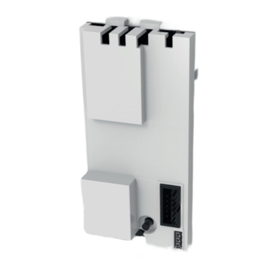
Overview Overview Unit description The Link home and Link pro interface modules can be used to access WOLF control components remotely in order to view states and levels and change parameters. Over a secure internet connection. The WOLF Link home is designed to be installed in an appliance. -
Page 6: Wolf Link Home Standard Delivery
KG Top, CKL Pool air handling equipment* CKL, CFL, CRL ventilation units* Combined heat and power modules in conjunction with a WOLF Link home compatible heating appliance, Full functional scope only with appliances running current software versions. * Modbus interface required in the appliance, special programming cannot be shown. -
Page 7: Function Of The Pushbutton
Access point active briefly off Flashing quickly WPS active Specification Designation WOLF Link home: 24 VDC via PCB WOLF Link pro: 5VDC via Micro USB Power supply and included power supply or 24VDC via “power supply terminals” IEEE 802.11b/g/n, 2.4GHz, channel 1 to... -
Page 8: Installation / Electrical Connection
X Switch OFF the power supply to the appliances X Secure the power supply against reconnection Installation site requirements Only install the Link home interface module in the specific installation locations intended. The WOLF Link pro may only be operated inside buildings and outside wet rooms. WOLF Link home installation CGB-2/CGW-2/CGS-2 and BWL-1S MGK-2 X Switch OFF the appliance and associated components... - Page 9 X In the case of network connection by network cable (LAN), plug this into the RJ45 socket on the WOLF Link home. X Switch on the appliance and associated components X You can now use the WOLF Link home (see instructions on the rear).
-
Page 10: Wolf Link Pro Installation
X Switch OFF the appliance and associated components X Disconnect the power supply (MCB or heating emergency stop switch) X Open the Wolf Link pro by undoing the screw and lifting up the cover on this side X Carefully break out the required cable entries with a suitable tool (e.g. -
Page 11: Decommissioning And Disposal
>0.5 mm²) to the eBUS terminals of your heating appliance or accessory controller. In so doing, pay attention to the polarity. X You can now use the WOLF Link pro (see instructions on the rear). X Next, reattach the cover and screw it in place. -
Page 12: Commissioning
5.1.2 WLAN 1) See page 8 for information on how to install the WOLF Link home or WOLF Link pro 2) Remove the network cable if connected 3) Turn on the power supply of the appliance and connect the WOLF Link...
Need help?
Do you have a question about the Link home and is the answer not in the manual?
Questions and answers