Table of Contents
Advertisement
TECHNICAL
TECHNICAL
GUIDE
GUIDE
SINGLE PACKAGE
AIR CONDITIONER / GAS HEAT
16 SEER – R-410A – 1 PHASE
2 THRU 5 NOMINAL TONS - 208/230V
50 - 125 MBH HEAT INPUT
MODELS: PCG6*24 THRU 60
Due to continuous product improvement, specifications
are subject to change without notice.
Visit us on the web at
www.upgnet.com
Additional rating information can be found at:
www.ahridirectory.org
WARRANTY SUMMARY*
Extended 10-Years limited parts and compressor warranty
Lifetime gas heat exchanger warranty with registration.
* Extended warranty requires online registration within 90 days of purchase for
replacement or closing for new home purchase. See limited warranty certificate
in User's Information Manual for details.
FOR DISTRIBUTION USE ONLY - NOT TO BE USED AT POINT OF RETAIL SALE
®
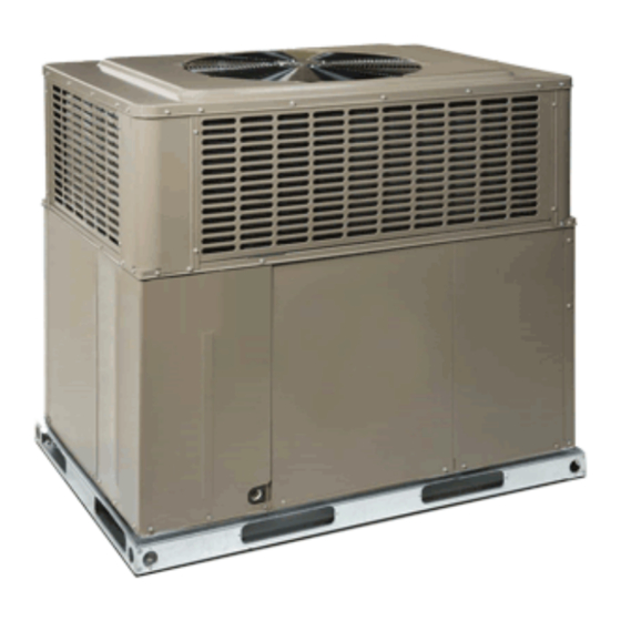
DESCRIPTION
These packaged cooling/heating air conditioners are designed
for outdoor installation. Only utility and duct connections are
required at the point of installation.
FEATURES
• Operating Efficiency - All PCG6 model gas units provide a
minimum AFUE of 81.0% in heating and 16.0 SEER, 12.0
EER rating for cooling operation. All models meet California
Low-Nox requirements of 40 ng/joule emission level for Air
Quality Management Districts.
• On Site Flexibility - All model sizes use a compact design
cabinet in one of two footprints. This provides installer flexi-
bility for placing the proper capacity unit on curbs or pads
with the smallest footprint after the internal load has been
determined. Field convertible duct connections from side
flow to downflow allows the installer to have greater flexibility
with less inventory.
• Lower Installation Cost - Installation time and costs are
reduced by easy power and control wiring connections. The
small base dimension means less space is required on the
ground or roof. All units are completely wired, charged with
R-410A and tested prior to shipment. Test stations using a
state-of-the-art computerized process system are used to
ensure product quality. Refrigerant charge and component
part numbers are verified via computers during assembly.
Vital run test statistics such as system pressure, motor cur-
rents, air velocity and temperature, unit vibration, and gas
system safeties are monitored and recorded by the system to
ensure unit performance. Equal size side supply and return
duct connections allow easy connection of ducts to match
low crawl spaces without transition pieces.
• Utility Connections Made Easy - Gas and electric utility
access provided through the bottom or the side of the unit.
Utility connections can be made quickly and with a minimum
amount of field labor. A field supplied and field installed elec-
trical disconnect switch must be installed.
• Convertible Airflow Design - The bottom duct openings are
covered when they leave the factory, ready to be used for a
side supply/side return application. If a bottom supply/bottom
return application is desired, simply remove the two panels
from the bottom of the unit and place them in the side supply/
side return duct openings. No panel cutting is required and
no accessory panel is necessary. Convertible airflow design
allows maximum field flexibility and minimum inventory.
• Condensate Pan - A corrosion-resistant, long-lasting, water-
tight pan is positioned below the evaporator coil to collect
and drain all condensate, preventing build-up of stagnant
condensate. The condensate pan conforms to ASHRAE 62-
89 standards (Ventilation for Acceptable Indoor Air Quality).
• Condensate Drain - The 3/4 inch NPT female connection is
rigidly mounted to assure proper fit and leak tight seal.
• Durable Finish - The cabinet is made of G90 galvanized
steel with a powder paint coating for appearance and protec-
tion. The pre-treated galvanized steel provides a better paint-
to-steel bond, which resists corrosion and rust creep. Powder
paint finish ensure less fading when exposed to sunlight, and
provides superior corrosion resistance (1000 hour salt spray
tested).
5219967-UTG-A-0716
Continued on next page.
Advertisement
Table of Contents

Related Manuals for York PCG6 24 Series


Summary of Contents for York PCG6 24 Series
- Page 1 5219967-UTG-A-0716 DESCRIPTION TECHNICAL TECHNICAL These packaged cooling/heating air conditioners are designed for outdoor installation. Only utility and duct connections are required at the point of installation. GUIDE GUIDE FEATURES • Operating Efficiency - All PCG6 model gas units provide a minimum AFUE of 81.0% in heating and 16.0 SEER, 12.0 EER rating for cooling operation.
- Page 2 5219967-UTG-A-0716 • Full Perimeter Base Rails - The easily removable base rails • Protected Compressor - The compressor is internally pro- provide a solid foundation for the entire unit and protects the tected against high pressure and temperature. This is unit during shipment.
-
Page 3: Component Location
5219967-UTG-A-0716 NOMENCLATURE 1. Model Family 5. Gas Heating Input BTU/Hr x 1000 PCG - packaged A/C with gas heat, 050 = 50,000 BTU/Hr. input, blank = electric heat PHG - packaged heat pump with gas heat, 6. Voltage-Phase-Frequency PCE - packaged A/C with electric heat, 2 = 208/230-1-60, 3=208/230-3-60, 4 = 460-3-60 PHE - packaged heat pump with electric heat 2. - Page 4 5219967-UTG-A-0716 ACCESSORIES • Rectangle to Round (Horizontal) Adapter (S1-1AK0110, S1-1AK0111) - Kit includes one supply and • Propane Conversion Kit (S1-1NP0704, S1-1NP0703) - Kit one return air rectangle to round duct adapter. Adapters are includes burner orifices, gas valve conversion and installa- preformed and designed to fit over current horizontal duct tion instructions necessary to field convert unit from natural openings on the base unit.
-
Page 5: Unit Cabinet
5219967-UTG-A-0716 GUIDE SPECIFICATIONS Outdoor Fan Assembly - The outdoor fan shall be of the direct-driven propeller type, discharge air vertically, have GENERAL aluminum blades riveted to corrosion resistant steel spider Units shall be manufactured by Unitary Products in an ISO bracket and shall be statically balanced for smooth operation. -
Page 6: Physical Data
5219967-UTG-A-0716 PHYSICAL DATA MODELS NOMINAL TONNAGE PCG6A24 PCG6A30 PCG6B36 PCG6B42 PCG6B48 PCG6B60 AHRI Cooling Performance Gross Capacity @ AHRI A point (MBH) 24.6 30.7 36.5 43.3 49.1 60.0 AHRI net capacity (MBH) 24.0 30.0 36.0 42.5 48.0 58.0 12.5 12.5 12.5 12.5 12.5... - Page 7 5219967-UTG-A-0716 COOLING PERFORMANCE DATA - 2 TON (LOW SPEED) PACKAGED UNIT MODEL NO. PCG6A24 ID CFM CONDENSER IDDB ENTERING AIR TEMPERATURE IDWB T.C. 16.4 19.6 18.7 21.6 23.6 18.8 21.6 20.9 23.5 25.4 21.3 23.6 23.1 25.5 27.1 55 / 45 S.C.
- Page 8 5219967-UTG-A-0716 COOLING PERFORMANCE DATA - 2.5 TON (LOW SPEED) PACKAGED UNIT MODEL NO. PCG6A30 ID CFM CONDENSER ENTERING AIR IDDB TEMPERATURE IDWB T.C. 21.3 24.1 24.3 26.9 28.5 24.0 26.2 26.1 28.7 30.6 26.7 28.3 27.9 30.6 32.6 55 / 45 S.C.
-
Page 9: Cooling Performance Data - 3 Ton (Low Speed)
5219967-UTG-A-0716 COOLING PERFORMANCE DATA - 3 TON (LOW SPEED) PACKAGED UNIT MODEL NO. PCG6B36 ID CFM 1000 CONDENSER ENTERING AIR IDDB TEMPERATURE IDWB T.C. 44.8 53.4 53.8 59.3 63.3 48.0 53.1 53.5 57.4 60.9 51.2 52.9 53.1 55.6 58.6 55 / 45 S.C. - Page 10 5219967-UTG-A-0716 COOLING PERFORMANCE DATA - 3.5 TON (LOW SPEED) PACKAGED UNIT MODEL NO. PCG6B42 ID CFM 1000 1200 CONDENSER ENTERING AIR IDDB TEMPERATURE IDWB T.C. 30.2 33.8 24.4 36.3 39.4 33.3 36.0 26.3 37.9 40.4 36.4 38.2 28.1 39.5 41.3 55 / 45 S.C.
-
Page 11: Cooling Performance Data - 4 Ton (Low Speed)
5219967-UTG-A-0716 COOLING PERFORMANCE DATA - 4 TON (LOW SPEED) PACKAGED UNIT MODEL NO. PCG6B48 ID CFM 1100 1300 CONDENSER ENTERING AIR IDDB TEMPERATURE IDWB T.C. 34.3 37.4 36.3 41.1 45.6 37.5 39.7 38.7 43.6 48.0 40.6 42.1 41.1 46.2 50.3 55 / 45 S.C. -
Page 12: Cooling Performance Data - 5 Ton (Low Speed)
5219967-UTG-A-0716 COOLING PERFORMANCE DATA - 5 TON (LOW SPEED) PACKAGED UNIT MODEL NO. PCG6B60 ID CFM 1100 1300 1500 CONDENSER ENTERING AIR IDDB TEMPERATURE IDWB T.C. 44.6 51.1 50.5 55.7 59.9 47.1 53.0 51.7 57.4 61.8 49.5 54.9 53.0 59.2 63.8 55 / 45 S.C. -
Page 13: Unit Dimensions
5219967-UTG-A-0716 COIL GUARD HIGH VOLTAGE CONNECTION 7/8” HIGH VOLTAGE COMBUSTION AIR INTAKE CONNECTION 1-3/32” HEAT EXCHANGER ACCESS PANEL COMPRESSOR ACCESS PANEL EXHAUST HOOD CONDENSATE DRAIN BLOWER LOW VOLTAGE CONNECTION ACCESS CONTROL ACCESS PANEL GAS SUPPLY PANEL A0296-001 UNIT DIMENSIONS Dimensions Model 51-1/4 35-3/4... -
Page 14: Electrical Data
5219967-UTG-A-0716 ELECTRICAL DATA OD Fan Supply Max Fuse Compressor Motor Blower Motor Model Voltage Breaker Size (Amps) (Amps) 24050 208/230-1-60 11.7 58.3 18.2 17.9 24075 208/230-1-60 11.7 58.3 18.2 19.1 30050 208/230-1-60 13.1 73.0 20.4 19.8 30075 208/230-1-60 13.1 73.0 20.4 21.0 36065... -
Page 15: Airflow Performance - Side Duct Application
5219967-UTG-A-0716 AIRFLOW PERFORMANCE - SIDE DUCT APPLICATION External Static Pressure (Inches WC) Model Jumper Position SCFM SCFM SCFM SCFM SCFM SCFM SCFM SCFM SCFM SCFM Continuous High Cool 24050 Low Cool High Heat Low Heat Continuous High Cool 24075 Low Cool 1184 1161 1124... - Page 16 5219967-UTG-A-0716 AIRFLOW PERFORMANCE - SIDE DUCT APPLICATION (Continued) External Static Pressure (Inches WC) Model Jumper Position SCFM SCFM SCFM SCFM SCFM SCFM SCFM SCFM SCFM SCFM 1076 1047 1011 Continuous 1152 1128 1090 1049 1005 1076 1047 1011 High Cool 1023 30075 Low Cool...
- Page 17 5219967-UTG-A-0716 AIRFLOW PERFORMANCE - SIDE DUCT APPLICATION (Continued) External Static Pressure (Inches WC) Model Jumper Position SCFM SCFM SCFM SCFM SCFM SCFM SCFM SCFM SCFM SCFM 1473 1435 1406 1368 1320 1264 1220 1164 1119 1060 Continuous 1304 1260 1218 1170 1116 1055...
- Page 18 5219967-UTG-A-0716 AIRFLOW PERFORMANCE - SIDE DUCT APPLICATION (Continued) External Static Pressure (Inches WC) Model Jumper Position SCFM SCFM SCFM SCFM SCFM SCFM SCFM SCFM SCFM SCFM 1674 1637 1615 1582 1540 1488 1445 1388 1351 1294 Continuous 1473 1435 1406 1368 1320 1264...
- Page 19 5219967-UTG-A-0716 AIRFLOW PERFORMANCE - SIDE DUCT APPLICATION (Continued) External Static Pressure (Inches WC) Model Jumper Position SCFM SCFM SCFM SCFM SCFM SCFM SCFM SCFM SCFM SCFM 2077 2043 2006 1961 1922 1880 1836 1789 1744 1696 Continuous 1879 1843 1807 1763 1723 1679...
-
Page 20: Additional Static Resistance
5219967-UTG-A-0716 ADDITIONAL STATIC RESISTANCE BOTTOM DUCT DIMENSIONS (Inches) Size (Tons) Wet Indoor Coil Economizer Filter/Frame Kit 0.01 0.00 0.01 0.01 0.00 0.02 0.01 0.00 0.04 0.02 0.01 0.06 024 (2.0) 0.03 0.01 0.08 1000 0.04 0.01 0.10 1100 0.05 0.01 0.13 1200 0.06... -
Page 21: Unit Typical Duct Applications
5219967-UTG-A-0716 UNIT TYPICAL DUCT APPLICATIONS ROOF CURB ROOF CURB INSTALLATION INSTALLATION REAR DUCT BOTTOM DUCT SLAB ON GROUND INSTALLATION A0324-001 UNIT TYPICAL SLAB ON GROUND INSTALLATION TO POWER SUPPLY RETURN AIR DUCT SUPPLY AIR DUCT FIELD-SUPPLIED DISCONNECT SWITCH CONDENSATE DRAIN MANUAL GAS SHUTOFF VAVLE CONTROL WIRING TO... -
Page 22: Unit Typical Roof Curb Installation
• Treat the negative number as a positive and add the two numbers together • This is total system static Subject to change without notice. Published in U.S.A. 5219967-UTG-A-0716 Copyright © 2016 by Johnson Controls, Inc. All rights reserved. Supersedes: Nothing York International Corp. 5005 York Drive Norman, OK 73069...
Need help?
Do you have a question about the PCG6 24 Series and is the answer not in the manual?
Questions and answers