Table of Contents
Advertisement
Advertisement
Table of Contents

Subscribe to Our Youtube Channel
Related Manuals for Libelium Waspmote Plug & Sense! Series


Summary of Contents for Libelium Waspmote Plug & Sense! Series
- Page 1 Waspmote Plug & Sense! Technical Guide...
-
Page 2: Table Of Contents
Index Document version: v8.6 - 05/2019 © Libelium Comunicaciones Distribuidas S.L. INDEX 1. General and safety information ..................6 2. Important: Read before use....................7 3. Introduction .......................... 8 4. Waspmote vs Waspmote Plug & Sense! ................9 5. General view ........................10 5.1. - Page 3 Index 13. Resetting Waspmote Plug & Sense! with an external magnet ........50 14. USB port ..........................52 14.1. Outdoors USB Cable ........................54 14.2. External SIM/USB socket ......................55 15. External solar panel ......................58 16. External Battery Module ....................60 16.1.
- Page 4 Index 24. Uploading code ........................98 25. Over the air programming – OTA .................. 104 25.1. Overview ............................104 25.2. OTA with 4G/WiFi modules via FTP ..................104 25.2.1. Setting the FTP server configuration ................105 26. Encryption libraries ......................106 27.
- Page 5 33.4. IC (Canada) ........................... 139 33.5. ANATEL (Brazil) ..........................139 33.6. RCM (Australia) ..........................140 33.7. Use of equipment characteristics .................... 141 34. Maintenance ........................142 35. Disposal and recycling ....................143 36. Resources ......................... 144 v8.6...
-
Page 6: General And Safety Information
All documents and any examples they contain are provided as-is and are subject to change without notice. • Except to the extent prohibited by law, Libelium makes no express or implied representation or warranty of any kind with regard to the documents, and specifically disclaims the implied warranties and conditions of merchantability and fitness for a particular purpose. -
Page 7: Important: Read Before Use
Do not expose Waspmote Plug & Sense! to temperatures below -20 ºC or above 60 ºC. • Do not power Waspmote with other power sources than the original provided by Libelium. Voltage and current • maximum ratings can be exceeded, stopping Waspmote working and voiding warranty. -
Page 8: Introduction
This guide explains the features related to our product line Plug & Sense! v15, released on October 2016. If you are using previous versions of our products, please use the corresponding guides, available on our Development website. You can get more information about the generation change on the document “New generation of Libelium product lines”. v8.6... -
Page 9: Waspmote Vs Waspmote Plug & Sense
Waspmote vs Waspmote Plug & Sense! 4. Waspmote vs Waspmote Plug & Sense! Waspmote is the original line in which developers have a total control over the hardware device. You can physically access to the board and connect new sensors or even embed it in your own products as an electronic sensor device. -
Page 10: General View
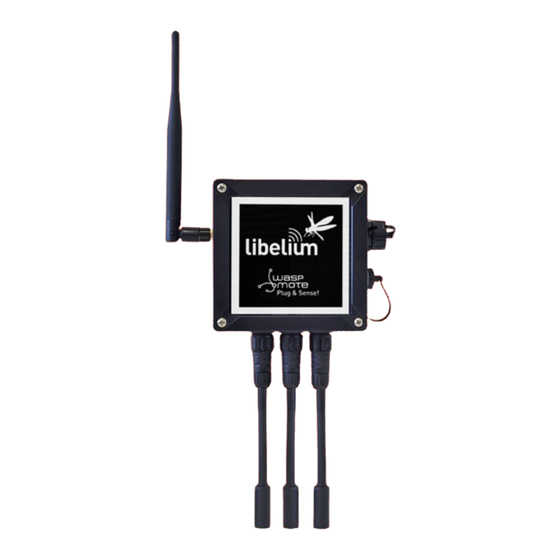
General view 5. General view This section shows main parts of Waspmote Plug & Sense! and a brief description of each one. In later sections all parts will be described deeply. 5.1. Specifications Material: polycarbonate • Sealing: polyurethane • Cover screws: stainless steel •... - Page 11 General view Figure: Control side of the enclosure Figure: Control side of the enclosure for 4G model Figure: Sensor side of the enclosure -11- v8.6...
- Page 12 General view Figure: Antenna side of the enclosure Figure: Front view of the enclosure Figure: Back view of the enclosure -12- v8.6...
-
Page 13: Parts Included
General view Figure: Warranty stickers of the enclosure Important note: Do not handle black stickers seals of the enclosure (Warranty stickers). Their integrity is the proof that Waspmote Plug & Sense! has not been opened. If they have been handled, damaged or broken, the warranty is automatically void. -
Page 14: Identification
General view 5.3. Identification Each Waspmote model is identified by stickers. Next figure shows front sticker. Model identification colour Enclosure model Figure: Front sticker of the enclosure There are many configurations of Waspmote Plug & Sense! line, all of them identified by one unique sticker. Next image shows all possibilities. - Page 15 General view Moreover, Waspmote Plug & Sense! includes a back sticker where it is shown identification numbers, radio MAC addresses, etc. It is highly recommended to annotate this information and save it for future maintenance. Next figure shows it in detail. Figure: Back sticker Sensor probes are identified too by a sticker showing the measured parameter and the sensor manufacturer reference.
-
Page 16: Sensor Probes
Always be sure you connected probes in the right socket, otherwise they can be damaged. Never connect a sensor not provided by Libelium to any of the sensor connectors. The electronics system inside can be damaged and the warranty will be automatically void. - Page 17 Besides that, there is a locking nut which should be screwed till the connector is completely fixed to the enclosure. Figure: Connecting a sensor probe to the enclosure Please use only sensors officially provided by Libelium. Any other sensor can damage Waspmote Plug & Sense! and void the warranty.
-
Page 18: Sensor Probes Types
Sensor probes 6.1. Sensor probes types Libelium provides many different sensor probes depending on what is going to be measured. This section describes main features of each type. If further information is required, please refer for the corresponding sensor board guide available on Libelium website. - Page 19 Sensor probes Luminosity - LDR probe This probe is designed to allow sunlight go thought a transparent protection. Figure: Luminosity probe Liquid Presence probe (point) This probe is designed to allow placing the sensor near its application. Figure: Liquid Presence probe (point) Liquid level probe This probe is designed to measure liquid levels.
- Page 20 Sensor probes Liquid flow probe This probe is designed to measure liquid flow through a pipe. Figure: Liquid flow probe Hall effect probe This probe is designed to control the opening of doors, windows, etc. Figure: Hall effect probe Solar radiation probe This probe is designed to measure solar radiation.
- Page 21 Sensor probes Soil temperature probe This probe is designed to be buried into the ground to measure its temperature. Figure: Soil temperature probe Soil moisture probe This probe is designed to be buried into the ground to measure its moisture. Figure: Soil moisture probe -21- v8.6...
- Page 22 Sensor probes Dendrometer probe This probe is designed to measure trunk, stem and fruit diameter of vegetables. Figure: Dendrometer probe Leaf wetness probe This probe is designed to measure wetness on vegetable leafs. Figure: Leaf wetness probe -22- v8.6...
- Page 23 Sensor probes Weather Station WS-3000 probe This probe is designed to measure wind direction, wind speed and rain. Figure: Weather Station WS-3000 probe Liquid Presence probe (line) This probe is designed to allow placing the sensor near its application. Figure: Liquid Presence probe (line) -23- v8.6...
- Page 24 Sensor probes Directionable type This type of probe is only for some sensors. The sensor is placed inside a plastic modular hose that allows us to point them where we want to measure with it. Figure: Configurations of directionable sensor probes -24- v8.6...
- Page 25 Sensor probes Sensor probes of this type are: Presence - PIR directionable probe • This probe is designed to allow infrared light trough a lens, necessary for presence applications. Figure: Presence (PIR) directionable probe Ultrasound sensor directionable probe • This probe is designed to measure distances using ultrasonic waves. Figure: Ultrasound directionable probe Luminosity (Luxes accuracy) directionable probe •...
- Page 26 Figure: Terminal box probe DB9 probe • The DB9 connector is commonly used in many applications with data transmission on industrial ambients. Libelium provides this probe with a standard DB9 female connector and a length of 1.5 meters. Figure: DB9 probe -26- v8.6...
-
Page 27: Extension Cord
Sensor probes 6.2. Extension cord This element is used when one sensor needs to be placed far from the node. Two lengths are available: 1.5 and 3 m. Next picture shows an extension cord. Figure: Extension cord accessory The extension cord has a female and a male connector. The first one (female) should be connected to the sensor probe. - Page 28 Sensor probes Moreover, the male connector should be connected to the enclosure as shown below. Figure: Connecting an extension cord to the enclosure -28- v8.6...
-
Page 29: Internal Sensors
Internal sensors 7. Internal sensors 7.1. Accelerometer Waspmote has a built-in acceleration sensor which informs the mote of acceleration variations experienced on each one of the 3 axes (X, Y, Z). The integration of this sensor allows the measurement of acceleration on the 3 axes (X, Y, Z), establishing 2 kinds of events: Free Fall and Direction Detection Change. -
Page 30: Radio Modules
Radio modules 8. Radio modules Waspmote Plug & Sense! may integrate many radio modules for wireless communications. Frequency Transmission Certification Radio Protocol Sensitivity Range* bands power XBee-PRO 802.15.4 802.15.4 2.4 GHz 10 dBm -100 dBm 750 m FCC, IC, XBee-PRO 802.15.4 802.15.4 2.4 GHz 18 dBm... -
Page 31: Xbee-Pro 802.15.4
Radio modules 8.1. XBee-PRO 802.15.4 Transmission Radio version Frequency Sensitivity Range* power XBee-PRO 802.15.4 EU 10 dBm 750 m 2.4 GHz -100 dBm XBee-PRO 802.15.4 18 dBm 1600 m * To determine your range, perform a range test under your operating conditions The frequency used is the free band of 2.4 GHz, using 12 channels with a bandwidth of 5 MHz per channel. - Page 32 Figure: Transmission power values Related API libraries: WaspXBeeCore.h, WaspXBeeCore.cpp, WaspXBee802.h, WaspXBee802.cpp All information about their programming and operation can be found in the 802.15.4 Networking Guide. All the documentation is located in the Development section in the Libelium website. -32- v8.6...
-
Page 33: Xbee Zigbee 3
Radio modules 8.2. XBee ZigBee 3 Radio version Frequency Transmission power Sensitivity Range* XBee ZigBee 3 2.4 GHz 8 dBm -103 dBm 1200 m * To determine your range, perform a range test under your operating conditions Figure: XBee ZigBee 3 As the ZigBee standard is supported in the IEEE 802.15.5 link layer, it uses the same channels as described in the previous section, with the peculiarity that the XBee ZigBee 3 model limits the number of channels to 16. - Page 34 Figure: Tree topology Related API libraries: WaspXBeeCore.h, WaspXBeeCore.cpp, WaspXBeeZB.h, WaspXBeeZB.cpp. All information about their programming and operation can be found in the ZigBee Networking Guide. All the documentation is located in the Development section in the Libelium website. -34- v8.6...
-
Page 35: Xbee 868Lp
Figure: Transmission power values Related API libraries: WaspXBeeCore.h, WaspXBeeCore.cpp, WaspXBee868LP.h, WaspXBee868LP.cpp All information about their programming and operation can be found in the 868 Networking Guide. All the documentation is located in the Development section in the Libelium website. -35- v8.6... -
Page 36: Xbee-Pro 900Hp
MAC address or that of the network. Figure: Star topology API libraries: WaspXBeeCore.h, WaspXBeeCore.cpp, WaspXBee900HP.h, WaspXBee900HP.cpp All information about their programming and operation can be found in the 900 Networking Guide. All the documentation is located in the Development section in the Libelium website. -36- v8.6... -
Page 37: Lorawan Modules
Radio modules 8.5. LoRaWAN modules LoRaWAN is a Low Power Wide Area Network (LPWAN) specification intended for wireless battery-operated devices in regional, national or global network. LoRaWAN target key requirements of Internet of things such as secure bi-directional communication, mobility and localization services. This standard will provide seamless interoperability among smart Things without the need of complex local installations and gives back the freedom to the user, developer, businesses enabling the role out of Internet of Things. - Page 38 Receiver: purchase your own base station or use networks from LoRaWAN operators Related API libraries: WaspLoRaWAN.h, WaspLoRaWAN.cpp All the information about their programming and operation can be found in the LoRaWAN Networking Guide available at Development section of Libelium website. -38- v8.6...
-
Page 39: Sigfox Modules
Radio modules 8.6. Sigfox modules Sigfox is a private company that aims to build a worldwide network especially designed for IoT devices. The network is cellular, with thousands of base stations deployed in each country. Sigfox technology offers very long ranges for low-power, battery-constrained nodes. - Page 40 Radio modules Related API libraries: WaspSigfox.h, Waspsigfox.cpp All information about their programming and operation can be found in the Sigfox Networking Guide. All the documentation is located in the Development section in the Libelium website. -40- v8.6...
-
Page 41: Wifi Pro Module
Instead of using a standard WiFi router as AP, the connection may be performed using a Meshlium device as AP. Meshlium is the multiprotocol router designed by Libelium which is specially recommended for outdoor applications as it is designed to resist the hardest conditions in real field deployments. For more information about Meshlium go to: http://www.libelium.com/meshlium. -
Page 42: Module
Radio modules 8.8. 4G module The 4G module enables the connectivity to high speed LTE, HSPA+, WCDMA cellular networks in order to make possible the creation of the next level of worldwide compatible projects inside the new “Internet of Things” era. This communication module is specially oriented to work with Internet servers, implementing internally several application layer protocols, which make easier to send the information to the cloud. - Page 43 All information about programming and operation can be found in the 4G Networking Guide. All the documentation is located in the Development section of Libelium website. Note: A rechargeable battery must be always connected when using this module (USB power supply is not enough). -43- v8.6...
-
Page 44: Industrial Protocols
Industrial Protocols 9. Industrial Protocols As an optional feature, it is possible to incorporate an Industrial Protocol module as a secondary communication module, besides the main radio interface of Waspmote Plug & Sense!. The available Industrial Protocols are RS-485, CAN Bus and Modbus (software layer over RS-485). This optional feature is accessible through an additional and dedicated socket on the antenna side of the enclosure. - Page 45 Industrial Protocols Figure: Terminal box probe connected to Plug & Sense! Each Industrial Protocol requires its own signals, wired on the female DB9 connector and on the Terminal box according to the next table: RS-485 CAN Bus Terminal Box Terminal Box DATA + (A) DATA + (A) CAN_H...
-
Page 46: Gps Module
GPS module 10. GPS module Any Plug & Sense! node can incorporate a GPS receiver in order to implement real-time asset tracking applications. The user can also take advantage of this accessory to geolocate data on a map. An external, waterproof antenna is provided;... -
Page 47: Internal Storage
Internal storage 11. Internal storage Waspmote Plug & Sense! has an internal SD (Secure Digital) card. FAT32 file system is used and cards up to 16 GB are supported. These cards need the bootloader #J to work properly. Note: Until February 2018, 2 GB SD cards were distributed; they operated with FAT16. From February to June, they were 8 GB. -
Page 48: On/Off Button
On/off button 12. On/off button This button is used to turn on or off Waspmote. It is a latch type button with two static positions as shown below. In on position, the button remains a bit lower than the LED ring. Figure: On/off button at off position Figure: Turning on Waspmote Note: The on/off button can be in on or off position to charge the battery. -
Page 49: External Led
On/off button 12.1. External LED The on/off button includes a red ring LED, which can be managed by software using dedicated functions described below. This LED can be used for instance to know that Waspmote is on, or for debugging purposes at developing phase. -
Page 50: Resetting Waspmote Plug & Sense! With An External Magnet
Resetting Waspmote Plug & Sense! with an external magnet 13. Resetting Waspmote Plug & Sense! with an external magnet Waspmote Plug & Sense! can be reset with an external magnet, with no contact. If one node stops working or if a defective behavior is detected, it would be costly to uninstall the node to bring it back to laboratory. - Page 51 Resetting Waspmote Plug & Sense! with an external magnet The magnet is made of neodymium. It is a special, high-power magnet. We only advise to use the magnet Libelium provides. The user must be careful because the magnet is so powerful that it can get stuck to metal objects. Besides, the magnet must be kept away from electronic devices like PCs, batteries, etc, since they could be damaged or information could be deleted.
-
Page 52: Usb Port
14. USB port This connector is used to upload code into Waspmote with a male to male USB cable provided by Libelium. Also, Plug & Sense! sends messages via this USB port. Just connect one side of the cable to this connector, removing protection cap and connect the other side to a PC to upload a code or to charge the internal rechargeable battery. - Page 53 USB port When uploading processes are finished, do not forget to screw firmly the protection cap to avoid connector damage. Never connect a USB which exceed maximum ratings of USB standard. Figure: Connecting USB charger For indoor deployments the nodes can be recharged using the USB charger. Figure: Charging the mote via USB -53- v8.6...
-
Page 54: Outdoors Usb Cable
USB port 14.1. Outdoors USB Cable The Outdoors USB Cable is made for outdoors applications with high power consumption requirements, where nodes need to be permanently powered. It consists of a 3-meter cable with the solar socket connector on one end, and a USB male A type on the other end. -
Page 55: External Sim/Usb Socket
USB port 14.2. External SIM/USB socket The External SIM/USB socket replaces the USB socket in two types of devices: Waspmote Plug & Sense! devices with 4G module • Meshlium devices with 4G module • The External SIM/USB socket is composed of 2 connectors: nano-SIM card •... - Page 56 The nano-SIM card connector allows the user to connect the SIM card he likes from the outside. It is not necessary to send a SIM card to Libelium for proper installation. You can ask your telecommunication provider for a nano- SIM card.
- Page 57 Figure: Inserting a SIM card with care in the External SIM/USB socket Note: From February 2018, Libelium has redesigned the SIM-USB connector, now it is more resistant and we have updated it using the most popular SIM card standard, nano-SIM.
-
Page 58: External Solar Panel
In the next picture a typical installation with external solar panel is shown. Notice that the enclosure is placed just under the solar panel, using it as a protection against sun and rain. Libelium provides special brackets in order to install it correctly. -58-... - Page 59 External solar panel Figure: Typical installation of the external solar panel -59- v8.6...
-
Page 60: External Battery Module
External Battery Module 16. External Battery Module The External Battery Module (EBM) is an accessory to extend the battery life of Plug & Sense!. The extension period may be from months to years depending on the sleep cycle and radio activity. The daily charging period is selectable among 5, 15 and 30 minutes with a selector switch and it can be combined with a solar panel to extend even more the node’s battery lifetime. - Page 61 External Battery Module Figure: External Battery Module’s Plug & Sense! connector Figure: Plug & Sense! with External Battery Module A solar panel can be attached to the solar panel connector, providing extra energy to the Plug & Sense! and extending the EBM life. Furthermore, if the charging period occurs while the solar panel is providing energy, the EBM will only provide the necessary current to fulfill the demand of the Plug &...
- Page 62 Figure: External Battery Module with a solar panel connected Figure: Plug & Sense! with External Battery Module and solar panel Finally, the EBM is compatible with all the Plug & Sense! product range, but it is not compatible with other Libelium products like Meshlium, Smart Parking or MySignals.
-
Page 63: Operating Modes
External Battery Module 16.2. Operating modes The EBM is designed to charge a Plug & Sense! node once per day during a preprogrammed period of time. There is a latch button to turn on and off the EBM. This button also includes a red LED to show the user when the device has started working. - Page 64 External Battery Module The operating mode determines the daily time that the system will be charging a node: Position 1 will set the charging time to 5 minutes per day • Position 2 will set the charging time to 15 minutes per day •...
-
Page 65: Vent Plug / Pressure Compensator
Vent plug / Pressure Compensator 17. Vent plug / Pressure Compensator The purpose of the Vent Plug is to avoid condensation by compensating external / internal pressure. Do not try to connect anything to this element and also do not modify its position or any of its parts. Figure: Vent plug of Waspmote Plug &... -
Page 66: Antenna
Antenna 18. Antenna By default, Waspmote Plug & Sense! has one external antenna with a standard SMA connector. This connector allows to connect the RF antenna. See next section for more information about other antenna options. Figure: Antenna connector of the enclosure To ensure good RF coverage, be sure that the antenna points to the sky and also be sure that the antenna is screwed completely to the connector. -
Page 67: Antennas For The Plug & Sense! 4G Model
Figure: Recommended tape Do not try to connect other kind of antennas which do not match with SMA standard connector and also other antennas not provided by Libelium. 18.1. Antennas for the Plug & Sense! 4G model The Waspmote Plug & Sense! models including a 4G radio will have 3 antenna connectors: the cellular main antenna, the cellular diversity antenna and the GPS antenna (GPS receiver is only available in 4G EU/BR). -
Page 68: Antennas For Plug & Sense! Gps-Ready Models
Antenna Figure: Diversity antenna (only 4G models) Note: The 4G radios for Australia and for US do not have a GPS receiver, so in this case, only 2 antennas are provided. Just leave the GPS antenna connector without any antenna. 18.2. - Page 69 Antenna Figure: Not used antenna connector (only GPS-ready models) Note: In order to achieve a better performance and maximum satellite visibility, the GPS antenna should be placed in an open-space location and oriented so that its reference arrow points vertically to the sky. -69- v8.6...
-
Page 70: Sensor Protection
However, a lot of sensor probes include just a standard protection. If the final application involves bad environmental conditions and a lot of sunlight hours, Libelium suggests the usage of a solar radiation shield. In addition, refer to corresponding section for more information about sensor probes. -
Page 71: Models
Models 21. Models There are some defined configurations of Waspmote Plug & Sense! depending on which sensors are going to be used. Waspmote Plug & Sense! configurations allow to connect up to six sensor probes at the same time. Each model takes a different conditioning circuit to enable the sensor integration. For this reason, each model allows connecting just its specific sensors. -
Page 72: Smart Environment Pro
Models 21.1. Smart Environment PRO The Smart Environment PRO model has been created as an evolution of Smart Environment. It enables the user to implement pollution, air quality, industrial, environmental or farming projects with high requirements in terms of high accuracy, reliability and measurement range as the sensors come calibrated from factory. Figure: Smart Environment PRO Waspmote Plug &... - Page 73 Note: For more technical information about each sensor probe go to the Development section on the Libelium website. Calibrated gas sensors are manufactured once the order has been placed to ensure maximum durability of the calibration feature. The manufacturing process and delivery may take from 4 to 6 weeks. The lifetime of calibrated gas sensors is 6 months working at maximum accuracy.
-
Page 74: Smart Security
Models 21.2. Smart Security The main applications for this Waspmote Plug & Sense! configuration are perimeter access control, liquid presence detection and doors and windows openings. Besides, a relay system allows this model to interact with external electrical machines. Figure: Smart Security Waspmote Plug & Sense! model Note: The probes attached in this photo could not match the final location. - Page 75 The sensor can be focused directly to the point we want. Figure: Configurations of the Presence sensor probe (PIR) Note: For more technical information about each sensor probe go to the Development section on the Libelium website. -75- v8.6...
-
Page 76: Smart Water
), Perchlorate (ClO ), Potassium (K ), Silver (Ag ), Sodium ) and pH. Take a look to the Smart Water Ions line in the next section. Refer to Libelium website for more information. Figure: Smart Water Plug&Sense! model -76- v8.6... - Page 77 Oxidation-Reduction Potential (ORP) 9329 Soil/Water Temperature 9255-P (included by default) Turbidity 9353-P Figure: Sensor sockets configuration for Smart Water model Note: For more technical information about each sensor probe go to the Development section on the Libelium website. -77- v8.6...
-
Page 78: Smart Water Xtreme
Refer to Libelium website for more information. Figure: Smart Water Xtreme Waspmote Plug & Sense! model -78- v8.6... - Page 79 72472 Ammonium 72473 Nitrate 72474 Chloride 72475 Sodium 72476 Calcium 72477 Figure: Sensor sockets configuration for Smart Water Xtreme model Note: For more technical information about each sensor probe go to the Development section on the Libelium website. -79- v8.6...
-
Page 80: Smart Water Ions
Take a look to the Smart Water line in the previous section. Refer to Libelium website for more information. There are 3 variants for Smart Water Ions: Single, Double and PRO. This is related to the type of ion sensor that each variant can integrate. - Page 81 Figure: Sensor sockets configuration for Smart Water Ions model, single variant Note: For more technical information about each sensor probe go to the Development section on the Libelium website. Double This variant includes a Double Junction Reference Probe, so it can read all the double type ion sensors.
- Page 82 9410 (included by default) Soil/Water Temperature 9255-P (included by default) Figure: Sensor sockets configuration for Smart Water Ions model, PRO variant Note: For more technical information about each sensor probe go to the Development section on the Libelium website. -82- v8.6...
-
Page 83: Smart Parking
Cloud. Figure: Smart Parking node Note: There are specific documents for parking applications on the Libelium website. Refer to the Smart Parking Technical Guide to see typical applications for this model and how to make a good installation. -
Page 84: Smart Agriculture Pro
The main applications for this Waspmote Plug & Sense! model are precision agriculture, irrigation systems, greenhouses, weather stations, etc. Refer to Libelium website for more information. Figure: Smart Agriculture PRO Waspmote Plug & Sense! model -84- v8.6... - Page 85 9325-P bus) Ultrasound (distance measurement) 9246-P Figure: Sensor sockets configuration for Smart Agriculture PRO model * Ask Libelium Sales Department for more information. Note: For more technical information about each sensor probe go to the Development section on the Libelium website.
-
Page 86: Smart Agriculture Xtreme
Models 21.8. Smart Agriculture Xtreme The Plug & Sense! Smart Agriculture Xtreme is an evolution of our Agriculture line with a new selection of high- end professional sensors. It allows to monitor multiple environmental parameters involving a wide range of applications, from plant growing analysis to weather observation. - Page 87 Models Sensor sockets are configured as shown in the figure below. Sensor probes allowed for each sensor socket Sensor Socket Parameter Reference Non-contact surface temperature measurement SI-411 9468-P Leaf and flower bud temperature SF-421 9467-P Soil oxygen level SO-411 9469-P Conductivity, water content and soil temperature 5TE 9402-P Conductivity, water content and soil temperature GS3...
- Page 88 Ultraviolet radiation SU-100 for Smart Agriculture Xtreme 9257-PX RS-232 type (generic) 4-20 mA type (generic) Figure: Sensor sockets configuration for Smart Agriculture model Note: For more technical information about each sensor probe go to the Development section on the Libelium website.z -88- v8.6...
-
Page 89: Ambient Control
Models 21.9. Ambient Control This model is designed to monitor the main environment parameters easily. Only three sensor probes are allowed for this model, as shown in next table. Figure: Ambient Control Waspmote Plug & Sense! model -89- v8.6... - Page 90 The sensor can be focused directly to the light source we want to measure. Figure: Configurations of the Luminosity sensor probe (luxes accuracy) Note: For more technical information about each sensor probe go to the Development section on the Libelium website. -90- v8.6...
-
Page 91: Smart Cities Pro
The main applications for this Waspmote Plug & Sense! model are noise maps (monitor in real time the acoustic levels in the streets of a city), air quality, waste management, smart lighting, etc. Refer to Libelium website more information. Figure: Smart Cities PRO Waspmote Plug & Sense! model -91- v8.6... - Page 92 Note: For more technical information about each sensor probe go to the Development section in Libelium website. Calibrated gas sensors are manufactured once the order has been placed to ensure maximum durability of the calibration feature. The manufacturing process and delivery may take from 4 to 6 weeks. The lifetime of calibrated gas sensors is 6 months working at maximum accuracy.
-
Page 93: Radiation Control
The rest of the other sensor sockets are not used. Figure: Radiation Control Waspmote Plug & Sense! model Sensor sockets are not used for this model. Note: For more technical information about each sensor probe go to the Development section on the Libelium website. -93- v8.6... -
Page 94: Ma Current Loop
Channel 3 (type 2 and type 3) 9270-P, DB9-P Channel 4 (type 4) 9270-P, DB9-P Figure: Sensor sockets configuration for 4-20 mA Current Loop model Note: For more technical information about each sensor probe go to the Development section on the Libelium website. -94- v8.6... -
Page 95: Programming
Programming 22. Programming Waspmote Plug & Sense! can be programmed using Libelium’s Integrated Development Environment (IDE). For further details on how to install the Waspmote IDE and how to compile and upload your first programs, we advise to read the “Waspmote IDE: User Guide”. This guide contains step-by-step indications to get started; it can be found on the Plug &... -
Page 96: Interruptions
Interrupt Programming Guide. All the documentation is located in the Development section in the Libelium website. 22.3.1. RTC Watchdog for reseting Waspmote One of the alarms of the RTC (Alarm 2) is connected to a Watchdog reset circuit that is able to reset the microcontroller of Waspmote Plug &... -
Page 97: Programming Cloud Service
Three license types: Basic, PRO and Elite • Easy licenses management • Summary reports • Just program any standard Plug & Sense! in minutes! • Check how easy it is to handle the Programming Cloud Service at: https://cloud.libelium.com/ Figure: Programming Cloud Service -97- v8.6... -
Page 98: Uploading Code
Uploading code 24. Uploading code Using the USB connector, a new code can be uploaded to Waspmote without opening Waspmote Plug & Sense!. Just connect one side of the USB cable to this connector, removing protection cap if necessary and connect the other side to a PC. - Page 99 Uploading code Step 2: Connect the USB cable to Waspmote Plug & Sense! Connect one end of the provided male-to-male USB cable to the USB connector. For models with 4G module, a micro-USB is supplied. Figure: Connecting the USB cable to Waspmote Plug & Sense! Step 3: Connect the USB cable to PC Connect the other end of the USB cable to your PC.
- Page 100 Now run Waspmote IDE on your PC. If you do not have Waspmote IDE already installed in your PC, then go to the Development section of Libelium website to download the latest version; there is a dedicated guide to help in the process: “Waspmote IDE: User Guide”.
- Page 101 Uploading code Step 6: Select the corresponding code Go to the examples menu and open your desired example. Then modify it according to your application and save the sketch with the save button, for instance with the name “Waspmote_Plug_Sense_test_code”, and check the IDE message “Done Saving”.
- Page 102 Uploading code Step 8: Select the USB port Select the corresponding serial port by going to tools/serial port. If you are unable to see the proper USB port maybe you should install the latest FTDI drivers. Figure: Selecting the USB port for Waspmote Plug & Sense! Note: the name of the USB ports depends on the OS and the particular PC you have.
- Page 103 Uploading code Step 10: Upload the code Now, press the upload button and see messages coming out from IDE. During a while you will see message “uploading to I/O board”. Figure: Uploading a code for Waspmote Plug & Sense! Wait a few seconds until the process ends and check there are no error messages, just “Done uploading” message. Step 11: Open the Serial Monitor If uploading processes are successfully completed, open Serial Monitor to see the output of the uploaded code.
-
Page 104: Over The Air Programming - Ota
Wireless Sensor Networks and the Internet of Things where the networks consist of hundreds or thousands of nodes OTA is taken to a new direction. Libelium provides an OTA method based on FTP transmissions to be used with 4G and WiFi modules. 25.2. OTA with 4G/WiFi modules via FTP It is possible to update the Waspmote’s program using Over The Air Programming and the following modules: 4G... -
Page 105: Setting The Ftp Server Configuration
Over the air programming – OTA 25.2.1. Setting the FTP server configuration The FTP server that Waspmote connects to needs a specific configuration so as to OTA work properly. There are two ways to set up the FTP server: Extern user’s FTP server: The user sets up an FTP server following the specific settings which are described within OTA Guide. -
Page 106: Encryption Libraries
Related API libraries: WaspAES.h, WaspAES.cpp • WaspRSA.h, WaspRSA.cpp • WaspHash.h, WaspHash.cpp • All information about their programming and operation can be found in the Encryption Programming Guide. All the documentation is located in the Development section in the Libelium website. -106- v8.6... -
Page 107: Interacting With Waspmote
Interacting with Waspmote 27. Interacting with Waspmote 27.1. Receiving XBee frames with Waspmote Gateway 27.1.1. Waspmote Gateway This device allows to collect data which flows through the sensor network into a PC or device with a standard USB port. Waspmote Gateway will act as a ”data bridge or access point” between the sensor network and the receiving equipment. -
Page 108: Linux Receiver
Figure: LEDs in Waspmote Gateway 27.1.2. Linux receiver When using Linux it is possible to use various applications to capture the input from the serial port. Libelium recommends to use the ‘Cutecom’ application. Once the application is launched, the speed and the USB where Waspmote has been connected must be configured. - Page 109 Interacting with Waspmote Figure: Cutecom application capturing Waspmote’s output Linux Sniffer As well as using the terminal to see the sensor information, an application which allows this captured data to be dumped to a file or passed to another program to be used or checked has been developed. File: “sniffer.c”...
- Page 110 Interacting with Waspmote #include <errno.h> #include <stdlib.h> #include <termios.h> /* Terminal control library (POSIX) */ #define MAX 100 main(int argc, char *argv[]) int sd=3; char *serialPort=””; char *serialPort0 = ”/dev/ttyS0”; char *serialPort1 = ”/dev/ttyS1”; char *USBserialPort0 = ”/dev/ttyUSB0”; char *USBserialPort1 = ”/dev/ttyUSBS1”; char valor[MAX] = ””;...
- Page 111 // or we reach the end of the string. Then we write it on the screen. if ((c==’\n’) || (j==(MAX-1))) int x; for (x=0; x<j; x++) write(2, &valor[x], 1); valor[x] = ’\0’; j = 0; close(sd); The code can be downloaded from: http://www.libelium.com/development/waspmote -111- v8.6...
-
Page 112: Windows Receiver
Interacting with Waspmote 27.1.3. Windows receiver If Windows is used, the application ‘Hyperterminal’ can be used to capture the output of the serial port. This application can be found installed by default in ‘Start/Programs/Accessories/Communication’, but if it is not available it can be downloaded from: http://hyperterminal-private-edition-htpe.en.softonic.com/ Once this application is launched the connection must be configured. - Page 113 Interacting with Waspmote The next step is to specify the speed and configuration parameters: Figure: Step 3 of establishing connection Once these steps have been performed connection with Waspmote has been established, and listening to the serial port begins. Figure: HyperTerminal application capturing Waspmote’s output. -113- v8.6...
-
Page 114: Mac-Os Receiver
Interacting with Waspmote 27.1.4. Mac-OS receiver If Mac OS X is used (version later than 10.3.9) the application ‘ZTERM’ can be used to capture the serial port output. This application can be downloaded from: http://homepage.mac.com/dalverson/zterm/ This application is configured automatically, establishing the USB on which Waspmote has been connected and the speed. - Page 115 Interacting with Waspmote 28. Meshlium - The IoT Gateway Figure: Meshlium device The sensor data gathered by the Waspmote Plug & Sense! nodes is sent to the Cloud by Meshlium, the IoT gateway router specially designed to connect Waspmote sensor networks to the Internet via Ethernet and 4G/3G/2G interfaces.
- Page 116 Meshlium. It allows to control all the interfaces and system options in a secure, easy and quick way. Figure: Meshlium Manager System All information about Meshlium can be found in the Meshlium Technical Guide. All the Meshlium documentation is located in the Development section in the Libelium website. -116- v8.6...
- Page 117 Interacting with Waspmote 28.3. Meshlium Visualizer Meshlium Visualizer is a plugin which plots graphs and maps with the data stored in the database. It can also export data in common formats. Meshlium Visualizer is a special software feature only available in the Meshlium units included in the IoT Vertical Kits (Smart Cities IoT Vertical Kit, Smart Water IoT Vertical Kit, etc).
- Page 118 Interacting with Waspmote 28.4. Cloud Connectors Meshlium allows developers to connect easily with third party cloud servers such as Amazon, IBM, Microsoft, Alibaba, Telefónica, ESRI, ThingWorks, etc. Just select the desired plugin in the Manager System and add the account info to synchronize the internal data base of Meshlium with the desired platform. -118- v8.6...
- Page 119 28.5. The Bridge The Bridge is a service on the cloud created by Libelium. It sends information from any IoT device to the main worldwide cloud platforms simultaneously and without having to implement each specific cloud protocol or authentication process.
-
Page 120: Installation
Installation 29. Installation The right behavior of Waspmote Plug & Sense! depends on a reliable installation. Libelium provides the necessary accessories to make it easy, like cable ties, mounting feet and other accessories. Wherever Waspmote Plug & Sense! is placed, please be sure you tight it firmly and the enclosure is not affected by wind, vibrations and other environmental conditions. - Page 121 Installation Figure: Using metal cable ties Solar panel bracket The solar panel brackets are used to achieve 45 degrees of inclination when a solar panel is used. Solar panel Figure: Solar panel bracket -121- v8.6...
- Page 122 Installation Waspmote Plug & Sense! accessories can vary depending on which configuration is acquired. See text and figure below to know which accessories are provided with each of the options. Figure: Waspmote Plug & Sense! accessories 1- Basic This configuration includes 4 mounting feet (A), 4 screws type 1 (B), 4 screws type 2 (C), 4 wall plugs (E) and 2 cable ties (I).
-
Page 123: Street Light Installation
29.2. Street Light installation The node can be fixed to a street light using the PVC coated stainless steel cable ties provided by Libelium. Always be sure that the enclosure is firmly tied and environmental elements (like wind) do not modify its position. Next pictures show examples of typical installation processes using the external solar panel in combination with the provided accessories. - Page 124 Installation Figure: Adding cable ties to the external solar panel Step 3: Secure Waspmote Plug & Sense! to the street light Place Waspmote Plug & Sense! on street light tightening firmly the metal cable ties. Be sure that the node remains completely tied to street light to avoid it could fall down.
- Page 125 Installation Step 4: Secure the external solar panel to the street light It is recommended to place the external solar panel above Waspmote Waspmote Plug & Sense!, using it as a roof. This will increase protection against rain and sunlight. Use cable ties and the dedicated holes of the solar panel bracket to complete Waspmote Plug &...
-
Page 126: Wall Installation
Installation 29.3. Wall installation Another typical installation of Waspmote Plug & Sense! is on walls. Using the mounting feet accessory, the node can be tied using provided screws and wall plugs. Next pictures show examples of typical installation processes using the external solar panel in combination with provided accessories. 29.3.1. - Page 127 Installation Step 3: Secure the external solar panel to a wall It is recommended to place the external solar panel above the node, using it as a roof. This will increase protection against rain and sun. Use screws and the dedicated holes of the solar panel bracket to complete the installation. Figure: Placing the external solar panel above Waspmote -127- v8.6...
-
Page 128: Energy Consumption
Energy Consumption 30. Energy Consumption 30.1. Consumption tables Waspmote 17 mA Sleep 30 uA Deep Sleep 33 uA Waspmote modules Transmission power Sending Receiving XBee-PRO 802.15.4 10 dBm 215 mA 55 mA XBee Zigbee 3 8 dBm 40 mA 17 mA XBee 868LP 14 dBm 48 mA... - Page 129 Off: By using Waspmote’s digital switches (controlled by the microcontroller), the module is switched off • completely. This mode has been implemented by Libelium as an independent layer of energy control, so that it can reduce consumption to a minimum (~7 μA) without relegating to techniques implemented by the manufacturer.
-
Page 130: Sleep Mode
Energy Consumption 30.2.2. Sleep mode In this mode, the main program is paused, the microcontroller passes to a latent state, from which it can be woken by all asynchronous interruptions and by the synchronous interruption generated by the Watchdog. When the Watchdog Timer is set up, the duration interval can be programmed from 16 ms to 8 s. -
Page 131: Deep Sleep Mode
Figure: From on to Deep Sleep mode 30.3. Lifetime of the sensors Libelium sensor probes are designed to increase lifetime of sensors when they are used outdoors. However, each sensor has a different lifetime depending on environmental conditions, usage and many other factors that Libelium cannot control. -
Page 132: Recommendations
• Temperature operating range is from -20 ºC to 60 ºC. Always ensure that the environment temperature is • between these limits. Libelium takes no responsibility of any damage to third parties caused by a bad installation. • -132- v8.6... -
Page 133: Documentation Changelog
Deleted references to the discontinued Smart Agriculture Sensor Board (“normal” version) • From v8.3 to v8.4 4G US module LE910 NAG was discontinued, now Libelium offers the LE910 NA V2 (different bands, no 2G and • no GPS) From v8.2 to v8.3 Renamed from Hive to Bridge •... - Page 134 Documentation changelog From v7.4 to v7.5 Changed description of the new External SIM/USB Socket version, now nano-SIM compliant • Changed specifications of the SD card, now 8 GB • Deleted references to the discontinued Internal Solar Panel • From v7.3 to v7.4 Added Programming Cloud Service section •...
-
Page 135: Certifications
Certifications 33. Certifications 33.1. General overview Products Europe Canada Australia Brazil Plug & Sense! 802.15.4 Plug & Sense! 802.15.4 RCM / CoC CoC / Anatel Plug & Sense! 868 Plug & Sense! 900 US Plug & Sense! 900 AU RCM / CoC Plug & Sense! 900 BR CoC / Anatel Plug &... -
Page 136: Waspmote Plug & Sense! 802.15.4 Eu
Certifications 33.2.1. Waspmote Plug & Sense! 802.15.4 EU Libelium Comunicaciones Distribuidas, S.L. declare under our sole responsibility that the product Waspmote Plug & Sense! 802.15.4 EU is in conformity with the essential requirements and other relevant requirements of the R&TTE Directive (1999/5/EC) and the 2002/95/CE Directive. The product is in conformity with the following... -
Page 137: Waspmote Plug & Sense! 4G Eu/Br
Certifications 33.2.4. Waspmote Plug & Sense! 4G EU/BR The product Waspmote Plug & Sense! 4G EU/BR is in conformity with the essential requirements and other relevant requirements of the R&TTE Directive (1999/5/EC) and the 2002/95/CE Directive. The product is in conformity with the following standards and/or other normative documents: Health and Safety: •... -
Page 138: Fcc (Usa)
Certifications 33.3. FCC (USA) This document applies to the following Waspmote Plug & Sense! models: Model FCC ID Waspmote Plug & Sense! 802.15.4 XKM-WPS-2400-V1 Waspmote Plug & Sense! 900 US XKM-WPS-900-V1 Waspmote Plug & Sense! WiFi XKM-WPS-WIFI-V1 Waspmote Plug & Sense! 4G US XKM-WPS-4G-V1 Waspmote Plug &... -
Page 139: Ic (Canada)
Certifications 33.4. IC (Canada) This document applies to the following Waspmote Plug & Sense! Models: Model IC ID Waspmote Plug & Sense! 802.15.4 8472A-WPS2400V1 Waspmote Plug & Sense! 900 US 8472A-WPS900V1 Waspmote Plug & Sense! WiFi 8472A-WPSWIFIV1 Waspmote Plug & Sense! 4G US 8472A-WPS4GV1 Waspmote Plug &... -
Page 140: Rcm (Australia)
Certifications 33.6. RCM (Australia) Figure: Back sticker for Waspmote Plug & Sense! 802.15.4 -140- v8.6... -
Page 141: Use Of Equipment Characteristics
Important: It is the responsibility of the installer to find out about restrictions of use for frequency bands in each country and act in accordance with the given regulations. Libelium Comunicaciones Distribuidas S.L does not list the entire set of standards that must be met for each country. -
Page 142: Maintenance
Maintenance 34. Maintenance Although Waspmote is a highly resistant product, please handle with care in order to enjoy a longer useful life. • Handle Waspmote Plug & Sense! with care, do not allow it to drop or move roughly. • Avoid placing the devices in areas reaching high temperatures that could damage the electronic components. -
Page 143: Disposal And Recycling
Disposal and recycling 35. Disposal and recycling When Waspmote Plug & Sense! reaches the end of its useful life it must be taken to a recycling point for • electronic equipment. The equipment should be disposed of separately from solid urban waste, please dispose of correctly. •... -
Page 144: Resources
Resources 36. Resources You can find complete information and support in the next sections in the Libelium Website: Development: http://www.libelium.com/products/plug-sense/ • Forum: http://www.libelium.com/forum/ • -144- v8.6...
Need help?
Do you have a question about the Waspmote Plug & Sense! Series and is the answer not in the manual?
Questions and answers