
Related Manuals for Schweitzer Engineering Laboratories SEL-421-4


Summary of Contents for Schweitzer Engineering Laboratories SEL-421-4
- Page 1 SEL-421 Relay Instruction Manual SEL-421-4, -5 Protection, Automation, and Control System Instruction Manual 20171021 *PM421-04-NB*...
- Page 2 SEL products appearing in this document may be covered by U.S. and Foreign patents. Schweitzer Engineering Laboratories, Inc. reserves all rights and benefits afforded under federal and international copyright and patent laws in its products, including without limitation software, firmware, and documentation.
-
Page 3: Table Of Contents
Table of Contents Instruction Manual List of Tables ....................................v List of Figures ..................................xiii Preface ......................................xix Manual Overview ..............................xix Safety Information .............................. xxii General Information.............................xxv Section 1: Introduction and Specifications Features .................................1.2 Models and Options ..............................1.5 Applications ................................1.8 Product Characteristics ............................1.12 Specifications..............................1.14 Section 2: Installation Shared Configuration Attributes ...........................2.1... - Page 4 Table of Contents Load-Encroachment Logic ..........................5.49 Out-of-Step Logic (Conventional) ........................5.50 Out-of-Step Logic (Zero Settings) ........................5.56 Mho Ground-Distance Elements ........................5.72 Quadrilateral Ground-Distance Elements ......................5.76 Mho Phase-Distance Elements ...........................5.80 Quadrilateral Phase-Distance Elements......................5.85 Zone Time Delay ..............................5.91 Instantaneous Line Overcurrent Elements ......................5.93 Inverse-Time Overcurrent Elements ........................5.99 Over- and Undervoltage Elements ........................5.113 Switch-Onto-Fault Logic ..........................5.117 Communications-Assisted Tripping Logic .......................5.120...
- Page 5 Firmware ................................A.1 ................................A.9 BOOT ICD File ................................A.9 Instruction Manual.............................A.10 Appendix B: Converting Settings From SEL-421-0, -1, -2, -3 to SEL-421-4, -5 Relay Word Bit Changes............................B.1 Analog Quantity Changes ............................ B.2 Global Settings Changes ............................B.3 Group Settings Changes............................B.3 Front-Panel Settings Changes ..........................
- Page 6 This page intentionally left blank...
- Page 7 List of Tables Table 1.1 Application Highlights ......................1.11 Table 1.2 SEL-421 Relay Characteristics....................1.13 Table 2.1 Recommended Control Input Pickup Settings................2.6 Table 2.2 Required Settings for Use with AC Control Signals ..............2.7 Table 2.3 Control Inputs ..........................2.15 Table 2.4 Control Outputs .........................2.15 Table 2.5 Main Board Jumpers........................2.16 Table 2.6...
- Page 8 List of Tables Table 5.33 Ground Directional Element Settings AUTO Calculations............5.35 Table 5.34 Ground Directional Element Preferred Settings ................5.35 Table 5.35 Ground Directional Element Enables ..................5.37 Table 5.36 Ground Directional Element Relay Word Bits................5.39 Table 5.37 Reference Table for Figure 5.23, Figure 5.24, and Figure 5.25..........5.42 Table 5.38 Vector Definitions for Equation 1.1 Through Equation 1.11 ............5.43 Table 5.39...
- Page 9 List of Tables Table 6.9 LOP Enable Options ........................6.25 Table 6.10 Tilt Resulting From Nonhomogeneity..................6.31 Table 6.11 Options for Enabling Pole-Open Logic ..................6.37 Table 6.12 Trip Unlatch Options .........................6.42 Table 6.13 Settings for 500 kV Parallel TX Example .................6.47 Table 6.14 System Data—345 kV Tapped Overhead Transmission Line ............6.54 Table 6.15 Secondary Impedances ......................6.55...
- Page 10 viii List of Tables Table 8.6 Control Inputs ..........................8.3 Table 8.7 Main Board Control Inputs......................8.3 Table 8.8 Interface Board #1 Control Inputs ....................8.4 Table 8.9 Interface Board #2 Control Inputs ....................8.4 Table 8.10 Settings Group Selection ......................8.5 Table 8.11 Frequency Estimation ........................8.5 Table 8.12 Time-Error Calculation........................8.5 Table 8.13...
- Page 11 List of Tables Table 8.63 Over Voltage (59) Element e.....................8.25 Table 8.64 Zone/Level Direction.........................8.26 Table 8.65 Directional Control Element......................8.26 Table 8.66 Pole-Open Detection........................8.26 Table 8.67 POTT Trip Scheme........................8.27 Table 8.68 DCUB Trip Scheme........................8.27 Table 8.69 DCB Trip Scheme ........................8.28 Table 8.70 Breaker 1 Failure Logic (and Breaker 2 Failure Logic) ............8.28 Table 8.71 Synchronism-Check Element Reference ...................8.29...
- Page 12 List of Tables Table 11.10 Relay Word Bits: Miscellaneous Elements ................11.43 Table 11.11 Relay Word Bits: Trip Logic Elements ...................11.43 Table 11.12 Relay Word Bits: Pilot Tripping Elements................11.45 Table 11.13 Relay Word Bits: Future Breaker Open-Phase Detector ............11.46 Table 11.14 Relay Word Bits: Breaker 1 Failure ..................11.46 Table 11.15 Relay Word Bits: Breaker 2 Failure ..................11.47...
-
Page 13: Firmware
List of Tables Table 11.68 Relay Word Bits: Bay Control Disconnect Timers and Breaker Status ........11.72 Table 11.69 Under/Overvoltage Elements ....................11.76 Table 11.70 Relay Word Bits: 81 Frequency Elements ................11.77 Table 11.71 Full-Cycle Mho and Quad Distance ..................11.78 Table 11.72 Time and Date Management....................11.79 Table 11.73 Remote Axion Status .......................11.79... - Page 14 This page intentionally left blank...
- Page 15 List of Figures Instruction Manual Figure 1.1 SEL-421 Functional Overview ....................1.2 Figure 1.2 Protecting a Line Segment With M Communications on a Fiber Channel...1.8 IRRORED Figure 1.3 Single Circuit Breaker Configuration (ESS := 1) ................1.8 Figure 1.4 Single Circuit Breaker Configuration With Line Breaker CTs (ESS := 2)........1.9 Figure 1.5 Double Circuit Breaker Configuration (ESS := 3) ..............1.9 Figure 1.6...
-
Page 16: Metering
List of Figures Figure 2.43 Topology 1..........................2.43 Figure 2.44 Topology 2..........................2.43 Figure 2.45 Topology 3..........................2.44 Figure 2.46 Remote Module Interface ......................2.45 Figure 2.47 SEL-421 to Computer—D-Subminiature 9-Pin Connector............2.47 Figure 2.48 Example Ethernet Panel With Fiber-Optic Ports...............2.48 Figure 2.49 Two 100BASE-FX Port Configuration on Ports 5A and 5B.............2.49 Figure 2.50 Two 10/100BASE-T Port Configuration on Ports 5A and 5B ..........2.49 Figure 2.51... - Page 17 List of Figures Figure 4.22 Bay With Ground Switch (Option 8)..................4.22 Figure 4.23 Bay Without Ground Switch (Option 9)..................4.23 Figure 4.24 Bay With Ground Switch (Option 10)..................4.23 Figure 4.25 Bay Without Ground Switch (Option 11)..................4.24 Figure 4.26 Left Breaker Bay With Ground Switch (Option 12) ..............4.24 Figure 4.27 Right Breaker Bay With Ground Switch (Option 13) ...............4.25 Figure 4.28...
- Page 18 List of Figures Figure 5.36 Open-Pole OSB Unblock Logic ....................5.56 Figure 5.37 Zero-Setting OOS Blocking Function ..................5.56 Figure 5.38 Swing Center Voltage Slope Detection Logic................5.58 Figure 5.39 Starter Zone Characteristic ......................5.59 Figure 5.40 Swing Signature Detector Logic....................5.60 Figure 5.41 Swing Signature Detector Logic....................5.61 Figure 5.42 Reset Conditions Logic ......................5.62 Figure 5.43...
- Page 19 List of Figures xvii Figure 5.92 DCB Logic Diagram........................5.124 Figure 5.93 Permissive Trip Receiver Logic Diagram ................5.129 Figure 5.94 POTT Logic Diagram ......................5.130 Figure 5.95 POTT Cross-Country Logic Diagram ..................5.131 Figure 5.96 POTT Scheme Logic (ECOMM := POTT3) With Echo and Weak Infeed......5.132 Figure 5.97 Permissive Trip Received Logic Diagram................5.135 Figure 5.98...
- Page 20 xviii List of Figures Figure 6.17 345 kV Tapped Line Zero-Sequence Network................6.75 Figure 6.18 DC Schematic for DCB Trip Scheme..................6.80 Figure 6.19 230 kV Parallel Underground Cables ..................6.87 Figure 6.20 Circuit Breaker Arrangement at Station S, Cable 1..............6.90 Figure 6.21 Quadrilateral Ground-Distance Element Reactive Reach Setting ..........6.95 Figure 6.22 Circuit to Determine Network Homogeneity ................6.97...
-
Page 21: Features
SEL-421 Versions and Supported Features on page 1.7 shows the relay features supported by versions SEL-421-4 and SEL-421-5. Throughout the manual, we provide margin notes next to the text explaining a feature to specify the availabil- ity of that feature in different versions of the relay. -
Page 22: Instruction Manual
Appendix B: Converting Settings From SEL-421-0, -1, -2, -3 to SEL-421-4, -5 Describes differences in settings, Relay Word bits, analog quantities, and DNP3 mapping between these versions of the relay. -
Page 23: Circuit Breaker Monitor
Preface Manual Overview Section 6: Autoreclosing Explains how to operate the SEL-400 series relay two-circuit breaker multishot recloser. Describes how to set the relay for single-pole reclosing, three-pole reclosing, or both. Shows selection of the lead and follow circuit breakers. Section 7: Metering Provides information on viewing current, voltage, power, and energy quantities. - Page 24 xxii Preface Safety Information Section 19: Remote Data Acquisition Describes the basic concepts of remote data acquisition systems. This includes both the Time-Domain Link (TiDL) remote data acquisition system, which uses SEL-2440 Axion modules to provide remote data acquisition and I/O communication, and UCA 61850-9-2LE Sampled Values.
- Page 25 Preface xxiii Safety Information Safety Marks The following statements apply to this device. General Safety Marks CAUTION ATTENTION There is danger of explosion if the battery is incorrectly replaced. Une pile remplacée incorrectement pose des risques d’explosion. Rem- Replace only with Ray-O-Vac no. BR2335 or equivalent recommended by placez seulement avec un Ray-O-Vac no BR2335 ou un produit équivalent manufacturer.
- Page 26 xxiv Preface Safety Information Other Safety Marks (Sheet 2 of 3) CAUTION ATTENTION Equipment components are sensitive to electrostatic discharge (ESD). Les composants de cet équipement sont sensibles aux décharges élec- Undetectable permanent damage can result if you do not use proper ESD trostatiques (DES).
-
Page 27: Applications
Preface General Information Other Safety Marks (Sheet 3 of 3) CAUTION ATTENTION Do not connect power to the relay until you have completed these proce- Ne pas mettre le relais sous tension avant d’avoir complété ces procé- dures and receive instruction to apply power. Equipment damage can dures et d’avoir reçu l’instruction de brancher l’alimentation. -
Page 28: Sel Boot
xxvi Preface General Information Logic Diagrams Logic diagrams in this manual follow the conventions and definitions shown below. NAME SYMBOL FUNCTION COMPARATOR Input A is compared to input B. Output C asserts if A is greater than B. — Input A comes from other logic. INPUT FLAG Either input A or input B asserted cause output C to assert. - Page 29 General Information Technical Support We appreciate your interest in SEL products and services. If you have questions or comments, please contact us at: Schweitzer Engineering Laboratories, Inc. 2350 NE Hopkins Court Pullman, WA 99163-5603 U.S.A. Tel: +1.509.338.3838 Fax: +1.509.332.7990 Internet: selinc.com/support...
- Page 30 This page intentionally left blank...
-
Page 31: Table 8.21 Dnp
You can organize automation of SEL OGIC differences among the SEL-421-4 and SEL-421-5. control equation programming into 10 blocks of 100 program lines each. The SEL-421 provides extensive communications interfaces from standard SEL... -
Page 32: Figure 1.1 Sel-421 Functional Overview
SEL-2600 Figure 1.1 SEL-421 Functional Overview SEL-421 features include the following: NOTE: Superior Protection. The SEL-421-4 does not Combine five zones of phase-distance and ground-dis- provide series-compensated line tance elements with directional overcurrent elements. Patented Coupling protection logic. Capacitor Voltage Transformer (CCVT) transient overreach logic enhances Zone 1 distance element security. -
Page 33: Specifications
NOTE: Automation. The SEL-421-4 has only one Take advantage of enhanced automation features that include 100-line automation programming programmable elements for local control, remote control, protection latch- block. - Page 34 Introduction and Specifications Features High-Accuracy Time Stamping. Time-tag binary COMTRADE event reports with real-time accuracy of better than 10 µs. View system state information to an accuracy of better than 1/4 of an electrical degree. Digital Relay-to-Relay Communication. Enhanced M communi- IRRORED cations to monitor internal element conditions between relays within a sta-...
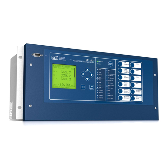
- Page 35 Introduction and Specifications Models and Options Part numbers 0421xxxxxxxxxx3Axxxxx, 0421xxxxxxxxxx7Axxxxx, 0421xxxxxxxxxx3Bxxxxx, and 0421xxxxxxxxxx7Bxxxxx designate relays with the auxiliary TRIP and CLOSE pushbuttons. The lowercase xs in the above part numbers represent fields that contain other values that are not important in determining the operator controls of the relay.
- Page 36 Introduction and Specifications Models and Options ➢ INT6: Contact inputs: 8 independent inputs (programmable pickup threshold); Contact outputs: 13 high-current interrupting Form A and 2 stan- dard Form C outputs ➢ INT7: Contact inputs: 8 independent inputs (level sensitive and optoisolated);...
- Page 37 Introduction and Specifications Models and Options SEL-421 Versions and Supported Features SEL-421 Features Protection 21MG Mho Ground-Distance and 21MP Mho Phase Distance Standard Standard 21XG Quadrilateral Ground-Distance and 21XP Quadrilateral Phase Distance Standard Standard High-Speed Distance and High-Speed Directional Standard 50N/G Ground, 50P Phase, and 50Q Negative-Sequence—O/C Standard Standard...
-
Page 38: Figure 1.3 Single Circuit Breaker Configuration (Ess := 1)
Introduction and Specifications Applications Applications Use the SEL-421 in a variety of transmission line protection applications. For information on connecting the relay, see Section 2: Installation. See Section 6: Protection Applications Examples for a description of various protection applica- tions using the SEL-421. The figures in this subsection illustrate common relay application configurations. -
Page 39: Figure 1.4 Single Circuit Breaker Configuration With Line Breaker Cts (Ess := 2)
Introduction and Specifications Applications SEL-421 Relay Analog Input Function CB1 protection, line protection CB1 breaker failure Line protection Synchronism check Figure 1.4 Single Circuit Breaker Configuration With Line Breaker CTs (ESS := 2) BUS 1 BUS 2 SEL-421 Relay Analog Input Function IW+IX Line Protection... -
Page 40: Figure 1.6 Double Circuit Breaker Configuration With Bus Protection (Ess := 4)
1.10 Introduction and Specifications Applications BUS 1 BUS 2 SEL-421 Relay Analog Input Function IW+IX CB2 protection Line protection CB1 protection Line protection Synchronism check Circuit Breaker 1 Synchronism check Circuit Breaker 2 Figure 1.6 Double Circuit Breaker Configuration With Bus Protection (ESS := 4) Tripping Direction SEL-421 Relay... -
Page 41: Table 1.1 Application Highlights
Apply the SEL-421 in power system protection and control situations. Table 1.1 lists applications and key features of the relay. NOTE: The SEL-421-4 does not Table 1.1 Application Highlights (Sheet 1 of 2) provide high-speed directional elements and high-speed distance... - Page 42 1.12 Introduction and Specifications Product Characteristics Table 1.1 Application Highlights (Sheet 2 of 2) Application Key Features Permissive Underreaching Supported by POTT logic Transfer Tripping (PUTT) Time-step distance backup protection schemes Directional Comparison Current reversal guard logic Blocking Trip (DCB) Carrier coordinating timers schemes Carrier send and receive extend logic...
-
Page 43: Table 1.2 Sel-421 Relay Characteristics
Introduction and Specifications 1.13 Product Characteristics Table 1.2 SEL-421 Relay Characteristics Characteristic Value Standard processing rate 8 times per cycle Battery monitor Autorecloser Single-pole MBG protocol Supported OGIC Protection freeform 250 lines Automation freeform 421-4: 1 block of 100 lines 421-5: 10 blocks of 100 lines each variables 64 protection... - Page 44 1.14 Introduction and Specifications Specifications Specifications Section 1Introduction and Specifications Instruction Manual Frequency and Rotation Note: If the relay uses a remote data acquisition system, such as TiDL, the operating times will be delayed by 1.5 ms. Use caution when setting the Nominal Frequency 50 ±5 Hz relay coordination times to account for this added delay.
- Page 45 Introduction and Specifications 1.15 Specifications Cyclic Capacity (2.5 Cycle/Second): MOV Protection: 330 Vdc/130 J 48 Vdc 0.50 A L/R = 40 ms Breaking Capacity (10,000 Operations): 125 Vdc 0.30 A L/R = 40 ms 48 Vdc 10 A L/R = 40 ms 250 Vdc 0.20 A L/R = 40 ms...
- Page 46 1.16 Introduction and Specifications Specifications Communications Ports Operating Temperature EIA-232: 1 Front and 3 Rear –40 to +85C (–40 to +185F) Serial Data Speed: 300–57600 bps Note: LCD contrast impaired for temperatures below –20° and above +70°C. Stated temperature ranges not applicable to UL applications. Communications Card Slot for Optional Ethernet Card Humidity Ordering Options:...
- Page 47 2000 samples/second SEL-421-5 Maximum 1000 samples/second Operating Time: 0.8 cycle at 70% of reach and SIR = 1 SEL-421-4 Maximum Output Format: Binary COMTRADE Operating Time: 1.5 cycle at 70% of reach and SIR = 1 Note: Per IEEE C37.111-1999, IEEE Standard Common Format for Quadrilateral Phase-Distance Elements Transient Data Exchange (COMTRADE) for Power Systems.
- Page 48 0.8 cycle at 70% of reach and SIR = 1 Curve Timing Accuracy: ±1.50 cycles plus ± 4% of curve time (for current between 2 and 30 multiples of SEL-421-4 Maximum pickup) Operating Time: 1.5 cycle at 70% of reach and SIR = 1...
-
Page 49: Station Dc Battery System Monitor
Introduction and Specifications 1.19 Specifications Time-Delay Accuracy: ±0.1% ±0.0042 s Accuracy (Steady State) Pickup Range, 5 A Model: ±5% of setting plus ±0.01 A for SIR Undervoltage Blocking: 20–200 V (Wye) (source to line impedance ratio) < 30 ±10% of setting plus ±0.01 A for Pickup Accuracy, 30 ... - Page 50 1.20 Introduction and Specifications Specifications Synchrophasor Metering Accuracy Number of Synchrophasor All metering accuracy is at 20°C, and nominal frequency unless Data Streams: otherwise noted. Number of Synchrophasors for Each Stream: Currents 15 Phase Synchrophasors (6 Voltage and 9 Currents) Phase Current Magnitude 5 Positive-Sequence Synchrophasors (2 Voltage and 3 Currents) 5 A Model:...
-
Page 51: Shared Configuration Attributes
Instruction Manual Instruction Manual S E C T I O N Installation The first steps in applying the SEL-421 Relay are installing and connecting the relay. This section describes common installation features and particular installa- tion requirements for the many physical configurations of the SEL-421. You can order the relay in horizontal and vertical orientations, and in panel-mount and rack-mount versions. - Page 52 Installation Shared Configuration Attributes Front-Panel Templates The horizontal front-panel template shown in Figure 2.1 is the same for all 3U, 4U, and 5U horizontal versions of the relay. The vertical front-panel template (shown in Figure 2.1) is the same for all 3U, 4U, and 5U vertical versions of the relay.
-
Page 53: Figure 2.1 Horizontal Front-Panel Template (A); Vertical Front-Panel Template
Installation Shared Configuration Attributes Operator Control Labels Target Opening Label Opening Target Label Operator Control Labels Opening Figure 2.1 Horizontal Front-Panel Template (a); Vertical Front-Panel Template (b) Rear Panels Rear panels are identical for the horizontal and the vertical configurations of the relay. -
Page 54: Figure 2.2 Rear 3U Template, Fixed Terminal Block Analog Inputs
Installation Shared Configuration Attributes Connector Types Screw-Terminal Connectors—I/O and Monitor/Power Connect to the relay I/O and Monitor/Power terminals on the rear panel through screw-terminal connectors. You can remove the entire screw-terminal connector from the back of the relay to disconnect relay I/O, dc battery monitor, and power without removing each wire connection. -
Page 55: Figure 2.3 Rear 3U Template, Connectorized Analog Inputs
Installation Shared Configuration Attributes (In a vertical-mount relay, the right rear side is at the top.) Figure 2.3 Rear 3U Template, Connectorized Analog Inputs Secondary Circuits The SEL-421 is a very low burden load on the CT secondaries and PT secondar- ies. -
Page 56: Table 2.1 Recommended Control Input Pickup Settings
Installation Shared Configuration Attributes Analog Input Module also sets its internal calculations based on this command. The relay internally transmits these data to the Axion modules and adjusts the appropriate scaling in the Axion module when this command is used. In addition to the CT nominal values, TiDL relays also require you to set the nominal frequency by issuing the CFG NFREQ command. -
Page 57: Table 2.2 Required Settings For Use With Ac Control Signals
Installation Shared Configuration Attributes The control input accuracy is ±5 percent of the applied signal plus ±3 Vdc. The maximum voltage input is 300 Vdc, and the relay samples the control inputs at 2 kHz. See Data Processing on page 9.1 in the SEL-400 Series Relays Instruction Manual. -
Page 58: Figure 2.4 Standard Control Output Connection
Installation Shared Configuration Attributes The recognition times listed in Table 2.2 are only valid when: ➤ The ac signal applied is at the same frequency as the power system. ➤ The signal is within the ac threshold pickup ranges defined in Optoisolated (Use With AC or DC Signals) on page 1.15. -
Page 59: Figure 2.5 Hybrid Control Output Connection
Installation Shared Configuration Attributes mechanical contact to interrupt (break) highly inductive dc currents. The contacts can carry continuous current, while eliminating the need for heat sinking and pro- viding security against voltage transients. With any hybrid output, break time varies according to the circuit inductive/resis- tive (L/R) ratio. -
Page 60: Figure 2.6 High-Speed, High-Current Interrupting Control Output Connection, Int5 (Int8)
2.10 Installation Shared Configuration Attributes OUT01 Figure 2.6 High-Speed, High-Current Interrupting Control Output Connection, INT5 (INT8) Figure 2.7 shows a representative connection for a Form A high-speed, high-cur- rent interrupting control output on the INT4 I/O interface terminals. The HS marks are included to indicate that this is a high-speed control output. -
Page 61: Figure 2.8 High-Speed, High-Current Interrupting Control Output Typical Terminals, Int5 (Int8)
Installation 2.11 Shared Configuration Attributes 1MΩ 1MΩ Figure 2.8 High-Speed, High-Current Interrupting Control Output Typical Terminals, INT5 (INT8) Figure 2.9 shows some possible connections for this third terminal that will elim- inate the false pick-up transients when closing an external switch. In general, you must connect the third terminal to the dc rail (positive or negative) that is on the same side as the open external switch condition. - Page 62 2.12 Installation Shared Configuration Attributes Every SEL-421 configuration includes the main board I/O and features these connections: ➤ Three hybrid (high-current interrupting) Form A outputs ➤ Two standard Form A outputs ➤ Three standard Form C outputs ➤ Seven high-isolation control inputs (five with no shared terminals and two with shared terminals) IRIG-B Inputs The SEL-421 has a regular IRIG-B timekeeping mode, and a high-accuracy...
-
Page 63: Figure 2.10 Int1 I/O Interface Board
Installation 2.13 Plug-In Boards An optional Ethernet card provides Ethernet capability for the SEL-421. An Ethernet card gives the relay access to popular Ethernet networking standards including TCP/IP, FTP, Telnet, DNP3, IEEE C37.118 Synchrophasors, and IEC 61850 over local area and wide area networks (the Ethernet card with IEC 61850 support is available at purchase as a factory-installed option). -
Page 64: Figure 2.13 Int4 I/O Interface Board
2.14 Installation Plug-In Boards Figure 2.13 INT4 I/O Interface Board Figure 2.14 INT5 I/O Interface Board Figure 2.15 INT6 I/O Interface Board Figure 2.16 INT7 I/O Interface Board Figure 2.17 INT8 I/O Interface Board The I/O interface boards carry jumpers that identify the board location (see Jumpers on page 2.15). -
Page 65: Table 2.3 Control Inputs
Installation 2.15 Jumpers Table 2.3 is a comparison of the I/O board input capacities; the table also shows the I/O inputs on the main board. See Control Inputs on page 1.15 for complete control input specifications. Table 2.3 Control Inputs Board Independent Contact Pairs Common Contacts INT1... -
Page 66: Table 2.5 Main Board Jumpers
2.16 Installation Jumpers Main Board Jumpers The jumpers on the main board of the SEL-421 perform these functions: ➤ Temporary/emergency password disable ➤ Circuit breaker and disconnect control enable ➤ Rear serial port +5 Vdc source enable Figure 2.19 shows the positions of the main board jumpers. The main board jumpers are in two locations. - Page 67 Installation 2.17 Jumpers Table 2.5 Main Board Jumpers (Sheet 2 of 2) Jumper Jumper Location Jumper Position Function BREAKER Front Disable circuit breaker com- mands (OPEN and CLOSE) and out- put PULSE commands (shipped position) Enable circuit breaker com- mands (OPEN and CLOSE) and output PULSE commands Front For SEL use only...
-
Page 68: Figure 2.19 Major Component Locations On The Sel-421 Main Board
2.18 Installation Jumpers J18 or J21 Figure 2.19 Major Component Locations on the SEL-421 Main Board Serial Port Jumpers Place jumpers on the main board to connect +5 Vdc to Pin 1 of each of the three rear-panel EIA-232 serial ports. The maximum current available from this Pin 1 source is 0.5 A. -
Page 69: Table 2.6 Main Board Jumpers-Jmp2, Jmp3, And Jmp4
Installation 2.19 Jumpers Table 2.6 describes the JMP2, JMP3, and JMP4 positions. Refer to Figure 2.19 for the locations of these jumpers. The SEL-421 ships with JMP2, JMP3, and JMP4 OFF (no +5 Vdc on Pin 1). Table 2.6 Main Board Jumpers—JMP2, JMP3, and JMP4 Jumper Jumper Jumper... - Page 70 2.20 Installation Jumpers Step 16. Reconnect any external cables that you removed from the relay in the disassembly process. Step 17. Follow your company standard procedure to return the relay to service. I/O Interface Board Jumpers Jumpers on the I/O interface boards identify the particular I/O board configura- tion and I/O board control address.
-
Page 71: Figure 2.20 Major Component Locations On The Sel-421 Int1, Int2, Int4, Int5, Int6, Int7, And Int8 I/O Boards
Installation 2.21 Jumpers Figure 2.20 Major Component Locations on the SEL-421 INT1, INT2, INT4, INT5, INT6, INT7, and INT8 I/O Boards Date Code 20171021 Instruction Manual SEL-421 Relay... -
Page 72: Figure 2.21 Major Component Locations On The Sel-421 Int3 I/O Board
2.22 Installation Jumpers Figure 2.21 Major Component Locations on the SEL-421 INT3 I/O Board To confirm the positions of your I/O board jumpers, remove the front panel and visually inspect the jumper placements. Table 2.7 lists the four jumper positions for I/O interface boards. -
Page 73: Table 2.7 I/O Board Jumpers
Installation 2.23 Jumpers The drawout tray on which each I/O board is mounted is keyed. See Section 10: Testing, Troubleshooting, and Maintenance in the SEL-400 Series Relays Instruc- tion Manual. Table 2.7 I/O Board Jumpers I/O Board Control JMP1A/ JMP1B/ JMP2A/ JMP2B/ Address... -
Page 74: Table 2.10 Front-Panel Led Option
2.24 Installation Relay Placement Table 2.10 Front-Panel LED Option JMP11, JMP12 LED Color BRIDGE Pins 1 and 3 Pins 2 and 4 BRIDGE Green Pins3 and 5 Pins 4 and 6 JMP11 Open; JMP12 Closed. Relay Placement Proper placement of the SEL-421 helps make certain that you receive years of trouble-free power system protection. -
Page 75: Figure 2.22 Sel-421 Chassis Dimensions
Installation 2.25 Connection Figure 2.22 SEL-421 Chassis Dimensions Panel Mounting Place the panel-mount versions of the SEL-421 in a switchboard panel. See the drawings in Figure 2.22 for panel cut and drill dimensions (these dimensions apply to both the horizontal and vertical panel-mount relay versions). Use the supplied mounting hardware to attach the relay. -
Page 76: Figure 2.23 3U Rear Panel, Main Board
2.26 Installation Connection Rear-Panel Layout Figure 2.23 through Figure 2.32 show available SEL-421 rear panels. All relay versions have screw-terminal connectors for I/O, power, and battery monitor. You can order the relay with fixed terminal blocks for the CT and PT connections, or you can order SEL Connectorized rear-panel configurations that feature plug-in/plug-out PT connectors and shorting CT connectors for relay ana- log inputs. -
Page 77: Figure 2.25 Ethercat Board For Tidl
Installation 2.27 Connection Figure 2.25 EtherCAT Board for TiDL Figure 2.26 4U Rear Panel, Main Board, Without Optional I/O Figure 2.27 4U Rear Panel, Main Board, INT5 I/O Interface Board Date Code 20171021 Instruction Manual SEL-421 Relay... -
Page 78: Figure 2.28 4U Rear Panel, Main Board, Int8 I/O Interface Board
2.28 Installation Connection Figure 2.28 4U Rear Panel, Main Board, INT8 I/O Interface Board (The INT3 board is the 200-addresses slot; the INT1 board is the 300-addresses slot.) Figure 2.29 5U Rear Panel, Main Board, INT3 and INT1 I/O Interface Board SEL-421 Relay Instruction Manual Date Code 20171021... -
Page 79: Figure 2.30 5U Rear Panel, Main Board, Int4 And Int1 I/O Interface Board
Installation 2.29 Connection (The INT4 board is the 200-addresses slot; the INT1 board is the 300-addresses slot.) Figure 2.30 5U Rear Panel, Main Board, INT4 and INT1 I/O Interface Board Figure 2.31 5U Rear Panel, Main Board, INT6 and INT4 I/O Interface Board Date Code 20171021 Instruction Manual SEL-421 Relay... -
Page 80: Figure 2.32 5U Rear Panel, Main Board, Int2 And Int7 I/O Interface Board
2.30 Installation Connection Figure 2.32 5U Rear Panel, Main Board, INT2 and INT7 I/O Interface Board Rear-Panel Symbols There are important safety symbols on the rear of the SEL-421 (see Figure 2.33). Observe proper safety precautions when you connect the relay at terminals marked by these symbols. -
Page 81: Figure 2.34 Screw-Terminal Connector Keying
Installation 2.31 Connection Step 2. To replace the screw-terminal connector, confirm that you have the correct connector and push the connector firmly onto the circuit board receptacle. Step 3. Reattach the two screws at each end of the block. Changing Screw-Terminal Connector Keying You can rotate a screw-terminal connector so that the connector wire dress posi- tion is the reverse of the factory-installed position (for example, wires entering the relay panel from below instead of from above). -
Page 82: Figure 2.35 Rear-Panel Receptacle Keying
2.32 Installation Connection Figure 2.35 Rear-Panel Receptacle Keying SEL-421 Relay Instruction Manual Date Code 20171021... -
Page 83: Figure 2.36 Power Connection Area Of The Rear Panel
Installation 2.33 Connection Grounding Connect the grounding terminal (#Z31) labeled GND on the rear panel to a rack frame ground or main station ground for proper safety and performance. This protective earthing terminal is in the lower right side of the relay panel (see Figure 2.23 through Figure 2.32). -
Page 84: Table 2.11 Fuse Requirements For The Power Supply
2.34 Installation Connection Table 2.11 Fuse Requirements for the Power Supply Operational Model Rated Voltage Fuse F1 Fuse Description Voltage Range Number 24–48 Vdc 18–60 Vdc T5.0AH250V 5x20 mm, time-lag, 5.0 A, 042142 or high break capacity, 250 V 042152 48–125 Vdc, 38–140 Vdc or T3.15AH250V 5x20 mm, time-lag, 3.15 A,... - Page 85 Installation 2.35 Connection Connectorized For the Connectorized SEL-421, order the wiring harness kit, SEL-WA0421. The wiring harness contains four prewired connectors for the relay current and volt- age inputs. You can order the wiring harness with various wire sizes and lengths. Contact your local Technical Service Center or the SEL factory for ordering information.
-
Page 86: Figure 2.37 Control Output Out108
2.36 Installation Connection Note that the main board I/O control inputs have one set of two inputs that share a common input leg and INT3 and INT4 I/O interface boards have two sets of nine inputs that share a common leg (see Figure 2.13). Assigning To assign the functions of the control inputs, see Operating the Relay Inputs and Outputs on page 3.61 in the SEL-400 Series Relays Instruction Manual for more... - Page 87 Installation 2.37 Connection Program OUT108 to respond to NOT HALARM by entering the following control equation with a communications terminal in QuickSet: OGIC OUT108 := NOT HALARM When the relay is operating normally, the NOT HALARM signal is at logical 1 and the b contacts of control output OUT108 are open.
-
Page 88: Figure 2.38 Axion Chassis
2.38 Installation Connection TiDL Connections SEL-421 Relays that support TiDL have a 4U chassis. The SEL-421 supports I/O on the main board as well as one additional I/O board. The main board and addi- tional I/O board map to the 100- and 200-level inputs and outputs. The Axion remote modules provide additional I/O for the 300, 400, and 500 levels and ana- log channels. -
Page 89: Figure 2.39 Sel-2243 Power Coupler
Installation 2.39 Connection Figure 2.39 SEL-2243 Power Coupler The SEL-2243 has sufficient power capacity to accommodate an entire Axion node. The terminal strip at the bottom of the unit (shown in Figure 2.39) is the connection point for incoming power. All Axion modules have a 55-position IEC C-style connector that provides a communications and power interface to the backplane. -
Page 90: Figure 2.40 Sel-2244-2 Digital Input Module
2.40 Installation Connection IN501–IN512 Fifth SEL-2244-2 DI Module IN513–IN524 Sixth SEL-2244-2 DI Module Figure 2.40 SEL-2244-2 Digital Input Module SEL-2244-5 Fast High-Current Digital Output Module The SEL-2244-5 Fast High-Current Digital Output Module consists of 10 fast, high-current output contacts. The outputs use the first 8 of the10 outputs and map as follows: First SEL-2244-5 DO Module OUT301–OUT308... -
Page 91: Figure 2.41 Sel-2244-5 Fast High-Current Digital Output Module
Installation 2.41 Connection Figure 2.41 SEL-2244-5 Fast High-Current Digital Output Module For both the DI and DO modules, use 24–12 AWG (0.2–3.31 mm ) wire of suffi- cient current capacity to connect to the digital input and output terminals for your application. -
Page 92: Figure 2.42 Sel-2245-42 Ac Analog Input Module
2.42 Installation Connection Figure 2.42 SEL-2245-42 AC Analog Input Module Topologies The SEL-421 Relay has a set of fixed topologies. These topologies map the volt- ages and currents internally in the relay to maintain existing settings and func- tionality. When the TiDL system is commissioned (see Commissioning on page 2.44), the firmware validates the connected Axion nodes and identifies if the installed CT/PT modules in the system match one of the supported topologies for the SEL-421. -
Page 93: Figure 2.43 Topology 1
Installation 2.43 Connection Substation Yard VAY, VBY, Line SEL Axion Port Analogs IAW, IBW, ICW SEL Axion SEL Axion IAX, IBX, ICX (optional) VAY, VBY, VCY IAX, IAW, VAZ (optional) IBX, IBW, VBZ (optional) VCZ (optional) SEL Axion SEL Axion 1 Phase 1 Phase (VAZ) -
Page 94: Figure 2.45 Topology 3
2.44 Installation Connection Substation Yard IAW, IBW, ICW IAW, IBW, ICW VAZ, VBZ, VAY, VAY, VBY, VBY, SEL Axion SEL Axion SEL Axion Feeder 1 Feeder 2 Feeder 3 Feeder 4 Port Analogs IAW, IBW, ICW, VAY, VBY, VCY IAX, IBX, ICX, VAZ, VBZ, VCZ SEL Relay SEL Relay (optional) -
Page 95: Table 2.12 Tidl Led Status
Installation 2.45 Connection The SEL-421 has a new interface on its back panel that replaces the original CT and PT input connections. These standard inputs are replaced with a remote mod- ule interface that supports eight fiber ports, labeled PORT 6A–PORT 6H (see Figure 2.46). - Page 96 2.46 Installation Connection Table 2.12 TiDL LED Status (Sheet 2 of 2) State Description LED Status Green COMMISSION LED Topology Mismatch Connection does not match supported topology Blinking Red COMMISSION LED Green LED: PORT 6A–PORT 6H OFF—mismatched/unused ON—matched Red LED: PORT 6A–PORT 6H Blinking—mismatched ON—matched OFF—ports unused...
-
Page 97: Figure 2.47 Sel-421 To Computer-D-Subminiature 9-Pin Connector
Installation 2.47 Connection Communications Ports Connections The SEL-421 has three rear-panel EIA-232 serial communications ports labeled PORT 1, PORT 2, and PORT 3 and one front-panel port, PORT F. For information on serial communication, see Establishing Communication on page 3.3, Serial Com- munication on page 15.2, and Serial Port Hardware Protocol on page 15.5 in the SEL-400 Series Relays Instruction Manual. -
Page 98: Figure 2.48 Example Ethernet Panel With Fiber-Optic Ports
2.48 Installation Connection The following list provides additional rules and practices you should follow for successful communication using EIA-232 serial communications devices and cables: ➤ Route communications cables well away from power and control circuits. Switching spikes and surges in power and control circuits can cause noise in the communications circuits if power and control circuits are not adequately separated from communications cables. -
Page 99: Figure 2.49 Two 100Base-Fx Port Configuration On Ports 5A And 5B
Installation 2.49 Connection Figure 2.49 Two 100BASE-FX Port Configuration on Ports 5A and 5B Figure 2.50 Two 10/100BASE-T Port Configuration on Ports 5A and 5B Figure 2.51 100BASE-FX and 10/100BASE-T Port Configuration on Ports 5A and 5B WARNING Do not perform any procedures or adjustments that this instruction manual does not describe. -
Page 100: Ac/Dc Connection Diagrams
2.50 Installation AC/DC Connection Diagrams Several types of STP bulk cable and patch cables are available for use in Ethernet networks. If noise in your environment is severe, you should consider using fiber- optic cables. We strongly advise against using twisted-pair cables for segments that leave or enter the control house. -
Page 101: Figure 2.55 Typical External Ac/Dc Connections-Single Circuit Breaker
Installation 2.51 AC/DC Connection Diagrams Trip Coil Breaker 1 (—) Trip OUT101 52A1 Circuit Close Coil Breaker 1 (—) Close OUT102 52B1 Circuit Lock Out Breaker Failure (—) OUT103 86B1 Trip Circuit Alarm to Circuit OUT108 Annunciator, RTU, Breaker or SEL-2020/2030 SEL-421 Relay Synch Check (—) -
Page 102: Figure 2.56 Typical External Ac/Dc Connections-Dual Circuit Breaker
2.52 Installation AC/DC Connection Diagrams BUS 1 Synchronism-Check Circuit Breaker 1 (—) Breaker 1 Trip Coil 52A1 Trip Circuit OUT101 (—) Breaker 1 Close Coil 52B1 Close Circuit OUT102 (—) Bus 1 BK1 CTs Breaker Failure Lock Out 86B1 OUT103 Trip Circuit (—) Permissive Trip Send... -
Page 103: Figure 2.57 Sel-421 Example Wiring Diagram Using The Auxiliary Trip/Close Pushbuttons
Installation 2.53 AC/DC Connection Diagrams Manual Trip Breaker Breaker Manual Close Pushbutton Open Closed Pushbutton Local Remote Close/ Auto-Reclose Remote Trips/ Protection Trips To Close Circuit — — Figure 2.57 SEL-421 Example Wiring Diagram Using the Auxiliary TRIP/CLOSE Pushbuttons Date Code 20171021 Instruction Manual SEL-421 Relay... - Page 104 This page intentionally left blank...
-
Page 105: Low-Level Test Interface
Instruction Manual Instruction Manual S E C T I O N Testing This section contains guidelines for determining and establishing test routines for the SEL-421 Relay. Follow the standard practices of your company in choosing testing philosophies, methods, and tools. Section 10: Testing, Troubleshooting, and Maintenance in the SEL-400 Series Relays Instruction Manual addresses the concepts related to testing. -
Page 106: Table 3.1 Uut Database Entries For Sel-5401 Relay Test System Software-5 A Relay
Testing Low-Level Test Interface Step 6. Reconnect the cables removed in Step 4 and replace the relay front- panel cover. Step 7. Reconnect any cables previously connected to serial ports on the front panel. Input Module Output (J3): 66.6 mV At Nominal Current (1 A or 5 A) 446 mV at Nominal Voltage (67 V Processing Module Input (J24): 6.6 Vp-p Maximum U.S. -
Page 107: Relay Test Connections
Testing Relay Test Connections Table 3.2 UUT Database Entries for SEL-5401 Relay Test System Software—1 A Relay (Sheet 2 of 2) Label Scale Factor Unit Relay Test Connections The SEL-421 is a flexible tool that you can use to implement many protection NOTE: The procedures specified in and control schemes. -
Page 108: Figure 3.2 Test Connections Using Three Voltage And Three Current Sources
Testing Relay Test Connections Connections for Three Voltage Sources and Three Current Sources Figure 3.2 shows the connections to use when you have three voltage sources and three current sources available. Three-Phase Voltage and Current Test Sources Relay Rear-Panel Analog Voltage and Current Inputs Figure 3.2 Test Connections Using Three Voltage and Three Current Sources SEL-421 Relay... -
Page 109: Figure 3.3 Test Connections Using Two Current Sources For Phase-To-Phase, Phase-To-Ground, And Two-Phase-To-Ground Faults
Testing Relay Test Connections Connections for Three Voltage Sources and Two Current Sources Figure 3.3 and Figure 3.4 show connections to use when you have three voltage sources and two current sources. You can use the connections shown in Figure 3.3 to simulate phase-to-phase, phase-to-ground, and two-phase-to- ground faults. -
Page 110: Figure 3.4 Test Connections Using Two Current Sources For Three-Phase Faults
Testing Relay Test Connections Three-Phase Voltage and Current Test Sources Relay Rear-Panel Analog Voltage and Current Inputs Figure 3.4 Test Connections Using Two Current Sources for Three-Phase Faults SEL-421 Relay Instruction Manual Date Code 20171021... -
Page 111: Figure 3.5 Test Connections Using A Single Current Source For A Phase-To-Ground Fault
Testing Relay Test Connections Connections for Three Voltage Sources and One Current Source Figure 3.5 and Figure 3.6 show connections to use when you have three voltage sources and a single current source. You can use the connections shown in Figure 3.5 to simulate phase-to-ground faults. -
Page 112: Figure 3.6 Test Connections Using A Single Current Source For A Phase-To-Phase Fault
Testing Checking Relay Operation Three-Phase Voltage and Current Test Sources Relay Rear-Panel Secondary Voltage and Current Inputs Figure 3.6 Test Connections Using a Single Current Source for a Phase-to- Phase Fault Checking Relay Operation The SEL-421 comes to you with all functions fully checked and calibrated so that the relay operates correctly and accurately. - Page 113 Testing Checking Relay Operation Brief functional tests and element verification confirm correct internal relay pro- cessing. This subsection discusses tests of the following relay elements: ➤ Overcurrent element: negative-sequence instantaneous, 50Q1 ➤ Directional element: negative-sequence portion, F32Q/R32Q, of the phase directional element, F32P/R32P ➤...
-
Page 114: Figure 3.7 Negative-Sequence Instantaneous Overcurrent Element Settings: Quickset
3.10 Testing Checking Relay Operation The relay asserts ground overcurrent elements when the 3I calculation exceeds the ground current element pickup setting. If balanced currents are applied to the relay, the relay reads 3I = 0 (load conditions) because the currents cancel in the calculation;... -
Page 115: Figure 3.8 Uploading Group 1 Settings To The Sel-421
If you see no error message, the new settings are loaded in the relay. NOTE: The Relay Editor dialog boxes shown in Figure 6.19 are for the SEL-421-5. The SEL-421-4 dialog boxes do not contain Automation 2 through Automation 10 setting instances. Figure 3.8 Uploading Group 1 Settings to the SEL-421 Step 3. -
Page 116: Figure 3.10 Relay Elements Screen Containing Element 50Q1
3.12 Testing Checking Relay Operation RELAY ELEMENTS ROW 26 ROW 27 67Q4 67Q3 67Q2 67Q1 50Q4 67Q4T =0 50Q3 67Q3T =0 50Q2 67Q2T =0 50Q1 67Q1T =0 SEARCH PRESS to search Figure 3.10 RELAY ELEMENTS Screen Containing Element 50Q1 Step 4. Connect a test source to the relay. a. - Page 117 Testing 3.13 Checking Relay Operation The result of Equation 3.1 is an impedance magnitude that varies with the magni- tude and angle of the applied current. Normally, a forward fault results in a nega- tive Z2c relay calculation. Test Current Solve Equation 3.1 to find the test current values that you need to apply to the relay to test the element.
-
Page 118: Figure 3.11 Group 1 Relay Configuration Settings: Quickset
3.14 Testing Checking Relay Operation Step 1. Configure the relay. a. Open QuickSet and read the present configuration in the SEL-421. b. Click Settings > Read. The relay sends all settings and configuration data to QuickSet. c. Expand the Group 1 settings and click the Relay Configuration branch of the Settings tree view as shown in Figure 3.11. -
Page 119: Figure 3.12 Breaker 1 Breaker Monitor Settings: Quickset
Testing 3.15 Checking Relay Operation i. Enter 1 in the text boxes for 52AA1 A-Phase N/O Contact Input -BK1, 52AB1 B-Phase N/O Contact Input -BK1, and 52AC1 C-Phase N/O Contact Input -BK1. The text boxes in Figure 3.12 appear if Breaker Monitor setting BK1TYP := 1. -
Page 120: Figure 3.13 Group 1 Line Configuration Settings: Quickset
3.16 Testing Checking Relay Operation Figure 3.13 Group 1 Line Configuration Settings: QuickSet SEL-421 Relay Instruction Manual Date Code 20171021... -
Page 121: Table 3.3 Negative-Sequence Directional Element Settings Auto Calculations
Testing 3.17 Checking Relay Operation Figure 3.14 Directional Settings: QuickSet Table 3.3 Negative-Sequence Directional Element Settings AUTO Calculations Setting Calculation 50FP 0.12 • I 50RP 0.08 • I 0.5 • Z1MAG Z2F + 1/(2 • I Step 3. Upload the new settings to the SEL-421. a. -
Page 122: Figure 3.15 Uploading Group 1 And Breaker Monitor Settings To The Sel-421
The Relay Editor dialog boxes Figure 3.15 shown in are for the SEL-421-5. The SEL-421-4 dialog boxes do not contain Automation 2 through Automation 10 setting Figure 3.15 Uploading Group 1 and Breaker Monitor Settings to the SEL-421 Step 4. Display the F32Q and R32Q Relay Word bits on the front-panel LCD screen. - Page 123 Testing 3.19 Checking Relay Operation Step 7. Use Equation 3.5 to determine the applied current angle (I TEST Z1ANG 180 84 96 – – TEST Step 8. Apply a test current to confirm operation of R32Q and F32Q. a.
-
Page 124: Figure 3.17 Finding Phase-To-Phase Test Quantities
3.20 Testing Checking Relay Operation The B-Phase to C-Phase current vector, I , is: – TEST Equation 3.10 Choose a convenient test source current magnitude, |I | = 2.5 A; then TEST | = 2 • |I | = 5 A. -
Page 125: Figure 3.18 Phase-Distance Elements Settings: Quickset
Testing 3.21 Checking Relay Operation The relay measures phase-distance element maximum reach when the faulted phase-to-phase current lags the faulted phase-to-phase voltage by the distance element maximum torque angle. In the SEL-421, the phase-distance element maximum torque angle is setting Z1ANG. Current I should lag voltage V Z1ANG. -
Page 126: Figure 3.19 Relay Elements Lcd Screen Containing Element Mbc2
3.22 Testing Checking Relay Operation Step 4. Upload the new settings to the SEL-421. a. Click File > Send. b. QuickSet prompts you for the settings class you want to send to the relay, as shown in the Group Select dialog box of Figure 3.15. -
Page 127: Technical Support
Z2MP reach setting. Technical Support We appreciate your interest in SEL products and services. If you have questions or comments, please contact us at: Schweitzer Engineering Laboratories, Inc. 2350 NE Hopkins Court Pullman, WA 99163-5603 U.S.A. Tel: +1.509.338.3838 Fax: +1.509.332.7990 Internet: selinc.com/support... - Page 128 This page intentionally left blank...
-
Page 129: Front-Panel Lcd Default Displays
Instruction Manual Instruction Manual S E C T I O N Front-Panel Operations The SEL-421 Relay front panel makes power system data collection and system control quick and efficient. Using the front panel, you can analyze power system operating information, view and change relay settings, and perform relay control functions. -
Page 130: Table 4.1 Metering Screens Enable Settings
Front-Panel Operations Front-Panel LCD Default Displays Table 4.1 Metering Screens Enable Settings Name Prompt Range Default RMS_V RMS Line Voltage Screen Y, N RMS_I RMS Line Current Screen Y, N RMS_VPP RMS Line Voltage Phase-to-Phase Screen Y, N RMS_W RMS Active Power Screen Y, N FUNDVAR Fundamental Reactive Power Screen... -
Page 131: Figure 4.1 Sample Rotating Display
Front-Panel Operations Front-Panel Menus and Screens ROTATING DISPLAY *Circuit BK1 SF6 Gas Press for menu ROTATING DISPLAY Circuit Breaker 1 --Closed-- Circuit BK1 SF6 Gas --Alarm-- Circuit Breaker 2 A PH= 119.6 A pri SF6 ALARM Press for menu ROTATING DISPLAY Line Current (A) RMS 119.6 IA =... - Page 132 Front-Panel Operations Front-Panel Menus and Screens trol, and settings for configuring the SEL-421 to your specific application needs. Use the following menus and screens to set the relay, perform local control actions, and read metering: ➤ Support Screens ➢ Contrast ➢...
- Page 133 Front-Panel Operations Front-Panel Menus and Screens NOTE: Global settings ESS (Enable Combinations of relay Global settings ESS and NUMBK give you metering data Source Selection) and NUMBK for Line, Circuit Breaker 1, and Circuit Breaker 2 when you view RMS METER (Number of Circuit Breakers) affect , and metering screens.
- Page 134 Front-Panel Operations Front-Panel Menus and Screens LINE METERING RMS LINE METER FUND LINE METER DEMAND METER VOLTAGE (kV) VOLTAGE (kV) CURRENTS (A) VA = x xxx.x VA = x xxx.x +xxx° IA PEAK = xxx xxx.x VB = x xxx.x VB = x xxx.x +xxx°...
- Page 135 Front-Panel Operations Front-Panel Menus and Screens LINE METERING ENERGY METER MAX/MIN LINE SYNCH CHECK ENERGY IN (MWh) CURRENTS (A) VPM = xxx.xxx V A = xx xxx.xx IA MAX = xx xxx.x BREAKER 1 MIN = xx xxx.x NVS1M xxx.xxx V B = xx xxx.xx IB MAX = xx xxx.x ANGLE1 = +xxx.xxx ˚...
- Page 136 Front-Panel Operations Front-Panel Menus and Screens EVENT SUMMARY 10002 EVENT SUMMARY 10002 EVENT SUMMARY 10002 EVENT SUMMARY 10002 03/15/2001 GROUP 1 TARGETS: TARGETS: FAULT QUANTITIES 00:00:05.387 COMM COMM (kV/A) EVENT: 87A REF ZONE 2 ZONE 2 VA = 0.7° FREQUENCY: 60.54 PHASE B PHASE B...
-
Page 137: Target Leds
Front-Panel Operations Target LEDs CONFIGURATION INFO FID=SEL-421-5-R101- V0-Z012012- D20100130 PART NUMBER: 0451541 5XC0X4H60X0XXX S/N=201001001 SELBOOT: BFID=SLBT-4XX- R205-V0-Z001002- D20100130 CHECKSUM: D97F CONFIGURATION INFO MAINBOARD: CODE FLASH: 4 MB DATA FLASH: 8 MB RAM: 3 MB EEPROM: 32 KB ANALOG INPUTS: W: CURRENTS: X: CURRENTS: Y: VOLTAGE: 67 V... -
Page 138: Table 4.2 Front-Panel Target Leds
4.10 Front-Panel Operations Target LEDs (13) (10) (14) (11) (15) (12) (16) (13) (17) (14) (18) (15) (19) (16) (20) (21) (10) (22) (11) (23) (12) (24) Figure 4.9 Factory-Default Front-Panel Target Areas (16 or 24 LEDs) Figure 4.9 shows the arrangement of the operation and target LEDs region into several areas described in Table 4.2. -
Page 139: Table 4.3 Time Target Led Trigger Elements-Factory Defaults
Front-Panel Operations 4.11 Target LEDs Table 4.3 TIME Target LED Trigger Elements—Factory Defaults Quadrilateral M2PT Z2GT M3PT Z3GT M4PT Z4GT M5PT Z5GT The COMM LED illuminates, indicating that tripping resulted from a communica- tions-assisted trip. The relay lights the COMM target when there is a relay tripping condition and the Relay Word bit COMPRM (communications-assisted trip per- mission) asserts. - Page 140 4.12 Front-Panel Operations Target LEDs Instantaneous and Time-Delayed Overcurrent The 50 target LED indicates that an instantaneous overcurrent element picked up. These elements are the nondirectional 50Pn phase overcurrent elements, 50Qn negative-sequence overcurrent elements, and the 50Gn ground overcurrent ele- ments, where n is the overcurrent level;...
-
Page 141: Table 4.4 Operator Control Pushbuttons And Leds-Factory Defaults
Front-Panel Operations 4.13 Front-Panel Operator Control Pushbuttons The IRIG LOCKED target LED illuminates when the relay detects synchronization to an external clock with less than 500 ns of jitter (Relay Word bit TIRIG is asserted). See Configuring Timekeeping on page 3.75 in the SEL-400 Series Relays Instruction Manual for complete details. - Page 142 4.14 Front-Panel Operations Front-Panel Operator Control Pushbuttons Press the operator control pushbuttons momentarily to toggle on and off the func- tions listed adjacent to each LED/pushbutton combination. The CLOSE and TRIP pushbuttons momentarily assert the close and trip relay outputs after a short delay.
-
Page 143: Figure 4.11 Factory-Default Operator Control Pushbuttons
Front-Panel Operations 4.15 One-Line Diagrams Operator OGIC Factory Control Setting Pushbutton LED Description Press this operator control pushbutton to enable/disable single-pole tripping. The PBn_LED corresponding LED illuminates to indicate the SPT ENABLED state. ENABLED = NOT E3PT #SPT ENABLED Press this operator control pushbutton to enable/disable communications-assisted tripping. PBn_LED COMM The corresponding LED illuminates to indicate the COMM SCHEME ENABLED state. -
Page 144: Figure 4.12 Bay Control Screen Selected For Rotating Display
4.16 Front-Panel Operations One-Line Diagrams Figure 4.12 Bay Control Screen Selected for Rotating Display You can also configure an HMI pushbutton to give you direct access to the bay control screen. Figure 4.13 shows an example of how to configure HMI Pushbut- ton 1 by selecting the BC option from the drop-down menu. -
Page 145: Figure 4.13 Configuring Pb1_Hmi For Direct Bay Control Access
Front-Panel Operations 4.17 One-Line Diagrams Figure 4.13 Configuring PB1_HMI for Direct Bay Control Access The Bay Control indicates the status of breakers in the one-line diagrams. The setting EPOLDIS, Enable Single-Pole Discrepancy Logic, controls the behavior. If the breaker is a single-pole type, Global Setting BKnTYP = 1, where n is 1 or 2, the breaker status will be determined based on the EPOLDIS setting. -
Page 146: Figure 4.14 Pole Discrepancy
4.18 Front-Panel Operations One-Line Diagrams BREAKER 1 OPEN CLOSED OPEN BREAKER 1 STATUS TRIP BREAKER 1 CLOSE BREAKER 1 Press TO ACTIVATE Figure 4.14 Pole Discrepancy Predefined Bay Control One-Line Diagrams Configurations The following pages illustrate all of the predefined busbar and bay control con- figurations in the SEL-421 defined by the (MIMIC settings). -
Page 147: Figure 4.15 Bay With Ground Switch (Option 1)
Front-Panel Operations 4.19 One-Line Diagrams Busbar Configurations Main Bus and Auxiliary Bus BAYNAME BUSNAM1 BUSNAM2 AQ_1 AQ_2 AQ_3 AQ_4 AQ_5 AQ_6 NAVIG Figure 4.15 Bay With Ground Switch (Option 1) BAYNAME BUSNAM1 BUSNAM2 AQ_1 AQ_2 AQ_3 AQ_4 AQ_5 AQ_6 NAVIG Figure 4.16 Bay Without Ground Switch (Option 2) Date Code 20171021 Instruction Manual... -
Page 148: Figure 4.17 Tie Breaker Bay (Option 3)
4.20 Front-Panel Operations One-Line Diagrams BAYNAME BUSNAM1 BUSNAM2 AQ_1 AQ_2 AQ_3 AQ_4 AQ_5 AQ_6 NAVIG Figure 4.17 Tie Breaker Bay (Option 3) Bus 1, Bus 2, and Transfer Bus BAYNAME BUSNAM1 BUSNAM2 BUSNAM3 AQ_1 AQ_2 AQ_3 AQ_4 AQ_5 AQ_6 NAVIG Figure 4.18 Bay With Ground Switch (Option 4) SEL-421 Relay Instruction Manual... -
Page 149: Figure 4.19 Bay Without Ground Switch (Option 5)
Front-Panel Operations 4.21 One-Line Diagrams BAYNAME BUSNAM1 BUSNAM2 BUSNAM3 AQ_1 AQ_2 AQ_3 AQ_4 AQ_5 AQ_6 NAVIG Figure 4.19 Bay Without Ground Switch (Option 5) Transfer Bay BAYNAME BUSNAM1 BUSNAM2 BUSNAM3 AQ_1 AQ_2 AQ_3 AQ_4 AQ_5 AQ_6 NAVIG Figure 4.20 Transfer Bay (Option 6) Date Code 20171021 Instruction Manual SEL-421 Relay... -
Page 150: Figure 4.21 Tie Breaker Bay (Option 7)
4.22 Front-Panel Operations One-Line Diagrams Tie Breaker Bay BAYNAME BUSNAM1 BUSNAM2 BUSNAM3 AQ_1 AQ_2 AQ_3 AQ_4 AQ_5 AQ_6 NAVIG Figure 4.21 Tie Breaker Bay (Option 7) Main Bus and Transfer Bus BAYNAME BUSNAM1 BUSNAM2 AQ_1 AQ_2 AQ_3 AQ_4 AQ_5 AQ_6 NAVIG Figure 4.22 Bay With Ground Switch (Option 8) SEL-421 Relay... -
Page 151: Figure 4.23 Bay Without Ground Switch (Option 9)
Front-Panel Operations 4.23 One-Line Diagrams BAYNAME BUSNAM1 BUSNAM2 AQ_1 AQ_2 AQ_3 AQ_4 AQ_5 AQ_6 NAVIG Figure 4.23 Bay Without Ground Switch (Option 9) Main Bus BAYNAME BUSNAM1 AQ_1 AQ_2 AQ_3 AQ_4 AQ_5 AQ_6 NAVIG Figure 4.24 Bay With Ground Switch (Option 10) Date Code 20171021 Instruction Manual SEL-421 Relay... -
Page 152: Figure 4.25 Bay Without Ground Switch (Option 11)
4.24 Front-Panel Operations One-Line Diagrams BAYNAME BUSNAM1 AQ_1 AQ_2 AQ_3 AQ_4 AQ_5 AQ_6 NAVIG Figure 4.25 Bay Without Ground Switch (Option 11) Breaker-and-a-Half BAYNAME BUSNAM1 BUSNAM2 AQ_1 AQ_2 AQ_3 AQ_4 AQ_5 AQ_6 NAVIG Figure 4.26 Left Breaker Bay With Ground Switch (Option 12) SEL-421 Relay Instruction Manual Date Code 20171021... -
Page 153: Figure 4.27 Right Breaker Bay With Ground Switch (Option 13)
Front-Panel Operations 4.25 One-Line Diagrams BAYNAME BUSNAM1 BUSNAM2 NAVIG Figure 4.27 Right Breaker Bay With Ground Switch (Option 13) BAYNAME BUSNAM1 BUSNAM2 BAYLAB1 BAYLAB2 NAVIG Figure 4.28 Middle Breaker Bay (Option 14) Date Code 20171021 Instruction Manual SEL-421 Relay... -
Page 154: Figure 4.29 Left Breaker Bay Without Ground Switch (Option 15)
4.26 Front-Panel Operations One-Line Diagrams BAYNAME BUSNAM1 BUSNAM2 AQ_1 AQ_2 AQ_3 AQ_4 AQ_5 AQ_6 NAVIG Figure 4.29 Left Breaker Bay Without Ground Switch (Option 15) BAYNAME BUSNAM1 BUSNAM2 AQ_1 AQ_2 AQ_3 AQ_4 AQ_5 AQ_6 NAVIG Figure 4.30 Right Breaker Bay Without Ground Switch (Option 16) SEL-421 Relay Instruction Manual Date Code 20171021... -
Page 155: Figure 4.31 Bay With Ground Switch (Option 17)
Front-Panel Operations 4.27 One-Line Diagrams Ring Bus BAYNAME BAYLAB1 BAYLAB2 AQ_1 AQ_2 AQ_3 AQ_4 AQ_5 AQ_6 NAVIG Figure 4.31 Bay With Ground Switch (Option 17) BAYNAME BAYLAB1 BAYLAB2 AQ_1 AQ_2 AQ_3 AQ_4 AQ_5 AQ_6 NAVIG Figure 4.32 Bay Without Ground Switch (Option 18) Date Code 20171021 Instruction Manual SEL-421 Relay... -
Page 156: Figure 4.33 Left Breaker Bay With Ground Switch (Option 19)
4.28 Front-Panel Operations One-Line Diagrams Double-Bus Double Breaker BAYNAME BUSNAM1 BUSNAM2 AQ_1 AQ_2 AQ_3 AQ_4 AQ_5 AQ_6 NAVIG Figure 4.33 Left Breaker Bay With Ground Switch (Option 19) BAYNAME BUSNAM1 BUSNAM2 AQ_1 AQ_2 AQ_3 AQ_4 AQ_5 AQ_6 NAVIG Figure 4.34 Left Breaker Bay Without Ground Switch (Option 20) SEL-421 Relay Instruction Manual Date Code 20171021... -
Page 157: Figure 4.35 Right Breaker Bay With Ground Switch (Option 21)
Front-Panel Operations 4.29 One-Line Diagrams BAYNAME BUSNAM1 BUSNAM2 AQ_1 AQ_2 AQ_3 AQ_4 AQ_5 AQ_6 NAVIG Figure 4.35 Right Breaker Bay With Ground Switch (Option 21) BAYNAME BUSNAM1 BUSNAM2 AQ_1 AQ_2 AQ_3 AQ_4 AQ_5 AQ_6 NAVIG Figure 4.36 Right Breaker Bay Without Ground Switch (Option 22) Date Code 20171021 Instruction Manual SEL-421 Relay... -
Page 158: Figure 4.37 Source Transfer (Option 23)
4.30 Front-Panel Operations One-Line Diagrams Source Transfer Bus BAYNAME BUSNAM1 BUSNAM2 AQ_1 AQ_4 AQ_2 AQ_5 AQ_3 AQ_6 BAYLAB1 NAVIG Figure 4.37 Source Transfer (Option 23) Throw-Over Bus BAYNAME AQ_1 BUS1 AQ_2 BUS2 AQ_3 AQ_4 AQ_5 AQ_6 NAVIG Figure 4.38 Throw-Over Bus Type 1 Switch (Option 24) SEL-421 Relay Instruction Manual Date Code 20171021... -
Page 159: Figure 4.39 Throw-Over Bus Type 2 Switch (Option 25)
Front-Panel Operations 4.31 One-Line Diagrams BAYNAME BUS1 BUS2 AQ_1 AQ_2 AQ_3 AQ_4 AQ_5 AQ_6 NAVIG Figure 4.39 Throw-Over Bus Type 2 Switch (Option 25) Panning When you specify a custom layout that is too large for one screen, you can take advantage of the panning feature to display sections not visible in the present screen view. -
Page 160: Figure 4.41 Screen 2
4.32 Front-Panel Operations One-Line Diagrams Screen 1 BKR1 BKR1 CT CT2 T2 C C T Common Area BKR2 B B K BK KR2 R2 2 K K R2 2 BKR3 Screen 2 Figure 4.41 Screen 2 As Figure 4.40 and Figure 4.41 show, panning is discontinuous and necessitates your toggling between two front-panel screens. - Page 161 8Instruction Manual Instruction Manual S E C T I O N Protection Functions NOTE: If the relay is using a remote This section provides a detailed explanation for each of the many SEL-421 Relay data acquisition system, such as TiDL, protection functions.
-
Page 162: Figure 5.1 Current And Voltage Source Connections For The Sel-421 Relay
Protection Functions Current and Voltage Source Selection ➤ Trip Logic on page 5.137 ➤ Circuit Breaker Failure Protection on page 5.146 ➤ Synchronism Check on page 5.158 Current and Voltage Source Selection The SEL-421 has two sets of three-phase current inputs (IW and IX) and two sets of three-phase voltage inputs (VY and VZ), as shown in Figure 5.1. -
Page 163: Figure 5.2 Main And Alternate Line-Current Source Assignments
Protection Functions Current and Voltage Source Selection Figure 5.4 shows the assignment of breaker currents for as many as two circuit breakers. These assigned breaker currents are used in breaker monitoring and breaker failure functions. These same breaker currents can also be assigned as line currents (e.g., line-current assignment LINE1 := IW in Figure 5.2). -
Page 164: Table 5.1 Available Current Source Selection Settings Combinations
Protection Functions Current and Voltage Source Selection Table 5.1 Available Current Source Selection Settings Combinations NUMBK LINEI ALINEI BK2I IPOL BK1I(Breaker 1 (number of (source (line-current (alternate line- (Breaker 2 (polarizing current source) breakers) selection) source) current source) current source) current) see Table 5.2 IAX, IBX, ICX,... -
Page 165: Table 5.3 Available Current Source Selection Settings Combinations When Ess := Y, Numbk := 2
Protection Functions Current and Voltage Source Selection Table 5.3 Available Current Source Selection Settings Combinations When ESS := Y, NUMBK := 2 NUMBK LINEI ALINEI BK1I BK2I IPOL (number of (source (line-current (alternate line- (Breaker 1 (Breaker 2 (polarizing breakers) selection) source) current source) -
Page 166: Table 5.4 Available Voltage Source Selection Setting Combinations
Protection Functions Current and Voltage Source Selection ➤ Series-compensation line logic ➤ Load-encroachment logic ➤ OOS (out-of-step) logic ➤ Distance elements ➤ Instantaneous line overcurrent elements ➤ Inverse-time overcurrent elements ➤ DCUB (directional comparison unblocking) trip scheme logic ➤ Metering on page 7.1, except synchrophasors Breaker current-source settings (BK1I and BK2I) identify the currents used in the following elements/features described in later in this section and in other sec- tions:... - Page 167 Protection Functions Current and Voltage Source Selection Table 5.4 Available Voltage Source Selection Setting Combinations (Sheet 2 of 2) NUMBK (number of ALINEV (alternate Line Voltage Source breakers) (source selection) line voltage source) VZ or NA VZ or NA NA = not applicable. Shaded cells indicate settings forced to given values and hidden.
-
Page 168: Table 5.5 Ess := N, Current And Voltage Source Selection
Protection Functions Current and Voltage Source Selection ESS := N, Single Circuit Breaker Configuration—One Current Input Set ESS to N for single circuit breaker applications with one current input. Figure 5.5 illustrates this application along with the corresponding current and voltage sources. -
Page 169: Table 5.7 Ess := 2, Current And Voltage Source Selection
Protection Functions Current and Voltage Source Selection Table 5.6 ESS := 1, Current and Voltage Source Selection (Sheet 2 of 2) Setting Prompt Entry Comments ALINEV Alternate Line Voltage Source (VZ, NA) ALTV Alternate Voltage Source (SEL Equation) Hidden OGIC Hidden when preceding setting is NA. -
Page 170: Table 5.8 Ess := 3, Current And Voltage Source Selection
5.10 Protection Functions Current and Voltage Source Selection Busbar 1 Busbar 2 Breaker 1 Breaker 2 SEL-421 Line 1 Line 2 Analog Input Function IW+IX Line protection CB1 protection CB2 protection Line protection Synchronism check Circuit Breaker 1 Synchronism check Circuit Breaker 2 Figure 5.7 ESS := 3, Double Circuit Breaker Configuration Table 5.8 ESS := 3, Current and Voltage Source Selection Setting... -
Page 171: Table 5.9 Ess := 4, Current And Voltage Source Selection
Protection Functions 5.11 Current and Voltage Source Selection BUS 1 BUS 2 LINE SEL-421 Relay Analog Input Function IW+IX CB2 protection Line protection CB1 protection Line protection Synchronism check Circuit Breaker 1 Synchronism check Circuit Breaker 2 Figure 5.8 ESS := 4, Double Circuit Breaker Configuration Table 5.9 ESS := 4, Current and Voltage Source Selection Setting Prompt... -
Page 172: Figure 5.9 Tapped Ehv Overhead Transmission Line
5.12 Protection Functions Current and Voltage Source Selection BK1S BK1R SEL-421 SEL-421 BK2S BK2R SEL-421 (HV) (LV) Figure 5.9 Tapped EHV Overhead Transmission Line Figure 5.10 illustrates the tapped overhead transmission line with a motor- operated disconnect (MOD) on the high side of a power transformer and two cir- cuit breakers on the low side. -
Page 173: Table 5.10 Ess := Y, Tapped Line
Protection Functions 5.13 Current and Voltage Source Selection Table 5.10 ESS := Y, Tapped Line Setting Prompt Entry Comments NUMBK Number of Circuit Breakers in Scheme (1, 2) LINEI Line Current Source (IW, COMB) ALINEI Alternate Current Source (IX, NA) ALTI Alternate Current Source (SEL Equation) -
Page 174: Polarizing Quantity For Distance Element Calculations
5.14 Protection Functions Polarizing Quantity for Distance Element Calculations Table 5.11 ESS := Y, Current Polarizing Source (Sheet 2 of 2) Setting Prompt Entry Comments ALTI Alternate Current Source (SEL Equation) Hidden OGIC BK1I Breaker 1 Current Source (IW, IX, NA) BK2I Breaker 2 Current Source (NA) Hidden... -
Page 175: Table 5.12 Vmemc Relay Setting
Protection Functions 5.15 Frequency Estimation essary. This setting provides less expansion of the distance element characteristics, while still providing security for zero-voltage three-phase faults. SEL recommends that you use this setting. If your application requires more expansion of the distance element characteris- tics, set VMEMC = 1. -
Page 176: Table 5.13 Frequency Measurement And Frequency Tracking Ranges
5.16 Protection Functions Frequency Estimation If the frequency is in the 20–80 Hz range, but outside the 40–65 Hz range (for example, 70 Hz), FREQP shows the frequency the relay measures and FREQ shows the clamped frequency. In this case, FREQP = 70 Hz and FREQ = 65 Hz. Table 5.13 summarizes the frequency measurement and frequency tracking ranges. -
Page 177: Table 5.15 Voltage And Breaker Pole Correlation
Protection Functions 5.17 Undervoltage Supervision Logic Table 5.14 Frequency Estimation (Sheet 2 of 2) Default Label Prompt Value VF02 Local Freq. Source 2 (ZERO, VAY, VBY, VCY, VAZ, VBZ, VCZ) VF03 Local Freq. Source 3 (ZERO, VAY, VBY, VCY, VAZ, VBZ, VCZ) VF11 Alt. -
Page 178: Figure 5.13 Undervoltage Supervision Logic
5.18 Protection Functions Undervoltage Supervision Logic Generally, settings VF01, VF02, VF03 correlate to VA, VB, and VC. Equation 5.2 shows the relationship between the peak amplitude of Valpha and the root-mean-square (RMS) value of the system voltage phasors for three-phase voltage inputs. -
Page 179: Table 5.17 Table Y12. Summary Of The Valpha And 81Uvsp Calculations
Protection Functions 5.19 Over- and Underfrequency Elements Case 2: Single-Phase PT Input, Connected to the A-Phase Input In this case, VF01 = VA, VF02 = ZERO, and VF03 = ZERO. Valpha 67 V • Equation 5.7 Valpha 94.75 V Equation 5.8 Set 81UVSP to 60 percent of this value: 81UVSP 94.75... -
Page 180: Figure 5.14 Frequency Element Logic
5.20 Protection Functions Over- and Underfrequency Elements Each frequency element can operate as an overfrequency or as an underfrequency element, depending on its pickup setting. If the element pickup setting (81DnP, n = 1–6) is less than the nominal system frequency setting, NFREQ, the element operates as an underfrequency element, picking up if measured frequency is less than the set point. -
Page 181: Table 5.18 Time-Error Calculation Inputs And Outputs
Protection Functions 5.21 Time-Error Calculation P (Level Pickup) Set the value at which you want the frequency element for each of six levels to assert. For a value of 81DnP less than the nominal system frequency NFREQ (50 or 60 Hz), the element operates as an underfrequency element. For a value greater than NFREQ, the element operates as an overfrequency element. -
Page 182: Figure 5.15 Sample Tec Command Response
5.22 Protection Functions Time-Error Calculation Table 5.18 Time-Error Calculation Inputs and Outputs (Sheet 2 of 2) INPUTS Description Global Settings NFREQ Nominal frequency (see Table 8.3 on page 8.2) LOADTE Load time-error correction factor (SEL control equation). A rising edge OGIC will cause the relay to load the TECORR analog quantity into TE. -
Page 183: Table 5.19 Fault Location Triggering Elements
Protection Functions 5.23 Fault Location Time Error Correction Preload Value TECORR = 2.250 s Relay Word Elements LOADTE = 0, STALLTE = 0, FREQOK = 1 Accumulated Time Error TE = -5.862 s ==> Figure 5.16 Sample TEC Command Response (Continued) Fault Location The SEL-421 computes distance to fault from data stored in the event reports. -
Page 184: Table 5.20 Fault Type
5.24 Protection Functions Open-Phase Detection Logic Table 5.20 Fault Type Label Fault Type A-Phase-to-ground B-Phase-to-ground C-Phase-to-ground A-Phase-to-B-Phase B-Phase-to-C-Phase C-Phase-to-A-Phase A-Phase-to-B-Phase-to-ground B-Phase-to-C-Phase-to-ground C-Phase-to-A-Phase-to-ground Three-phase Table 5.21 Fault Location Settings Default Setting Prompt Range (5 A) Z1MAG Positive-Sequence Line Impedance Magnitude () (0.25–1275)/I 7.80 Z1ANG Positive-Sequence Line Impedance Angle (°) -
Page 185: Table 5.23 Open-Phase Detection Relay Word Bits
Protection Functions 5.25 Pole-Open Logic Table 5.23 Open-Phase Detection Relay Word Bits Name Description B1OPHA Breaker 1 A-Phase open B1OPHB Breaker 1 B-Phase open B1OPHC Breaker 1 C-Phase open B2OPHA Breaker 2 A-Phase open B2OPHB Breaker 2 B-Phase open B2OPHC Breaker 2 C-Phase open LOPHA Line A-Phase open... - Page 186 5.26 Protection Functions Pole-Open Logic Table 5.26 Pole-Open Logic Relay Word Bits (Sheet 2 of 2) Name Description SPOC C-Phase open One or two poles open All three poles open 27APO A-Phase undervoltage—pole open 27BPO B-Phase undervoltage—pole open 27CPO C-Phase undervoltage—pole open SEL-421 Relay Instruction Manual Date Code 20171021...
-
Page 187: Figure 5.17 Pole-Open Logic Diagram
Protection Functions 5.27 Pole-Open Logic Figure 5.17 Pole-Open Logic Diagram Date Code 20171021 Instruction Manual SEL-421 Relay... -
Page 188: Loss-Of-Potential Logic
5.28 Protection Functions Loss-of-Potential Logic Loss-of-Potential Logic Fuses or molded case circuit breakers often protect the secondary windings of the power system potential transformers. Operation of one or more fuses or molded case circuit breakers results in a loss of polarizing potential inputs to the relay. Loss of one or more phase voltages prevents the relay from discriminating fault distance and direction properly. -
Page 189: Table 5.27 Lop Logic Setting
Protection Functions 5.29 Loss-of-Potential Logic Setting ELOP := Y If you set ELOP to Y and an LOP condition occurs, the voltage-polarized direc- tional elements and all distance elements are disabled. The forward-looking directional overcurrent elements effectively become nondirectional and provide overcurrent protection during an LOP condition. -
Page 190: Figure 5.18 Lop Logic Process Overview
5.30 Protection Functions Loss-of-Potential Logic |V1| |I1| START decreasing? changing? ∠ I1 changing? |3I0| changing? ∠ 3I0 changing? Declare Figure 5.18 LOP Logic Process Overview The following text gives additional description of the steps shown in Figure 5.18: NOTE: (1) Magnitude of positive-sequence voltage is decreasing. When an enabled breaker is Measure positive- set to single-pole open mode, and a... - Page 191 Protection Functions 5.31 Loss-of-Potential Logic (4) Zero-sequence current magnitude is not changing. Measure zero-sequence current magnitude (|I |) and compare it to |I | from one cycle ear- 0(k–1 cycle) lier. If this difference is greater than six percent nominal current, the condi- tion measured is not an LOP, even if all other conditions are met.
-
Page 192: Figure 5.19 Lop Logic
5.32 Protection Functions Loss-of-Potential Logic Figure 5.19 LOP Logic SEL-421 Relay Instruction Manual Date Code 20171021... -
Page 193: Table 5.29 Fault Type Identification Logic Settings
Protection Functions 5.33 Fault Type Identification Selection Logic Fault Type Identification Selection Logic The fault type identification selection (FIDS) logic is enabled by the Group Set- ting EFID. This logic identifies the faulted phase(s) for all faults involving ground by comparing the angle between I and I For cases where only zero-sequence current flows through the relay terminal (that is, no negative-sequence current and no positive-sequence current), the... -
Page 194: Table 5.32 Ground Directional Element Settings
5.34 Protection Functions Ground Directional Element The negative-sequence voltage polarized directional element 32QG listed in Table 5.31 supervises the ground-distance elements and residual ground direc- tional overcurrent elements. The negative-sequence voltage polarized directional element 32Q illustrated in Figure 5.28 only supervises the phase-distance ele- ments. -
Page 195: Table 5.33 Ground Directional Element Settings Auto Calculations
Protection Functions 5.35 Ground Directional Element Table 5.33 Ground Directional Element Settings AUTO Calculations Setting Equation 50FP 0.12 • I 50RP 0.08 • I 0.5 • Z1MAG Z2F + 1/(2 • I 0.5 • Z0MAG Z0F + 1/(2 • I Use caution when you set E32 = AUTO. - Page 196 5.36 Protection Functions Ground Directional Element Setting 50RP is the threshold for the current level detector that enables reverse decisions for both the negative- and zero-sequence voltage-polarized directional elements. If the magnitude of 3I or 3I is greater than 50RP, the corresponding directional element can process a reverse decision.
-
Page 197: Table 5.35 Ground Directional Element Enables
Protection Functions 5.37 Ground Directional Element ORDER The SEL-421 uses Best Choice Ground Directional Element logic to determine the order in which the relay selects 32QG, 32V, or 32I to provide directional deci- sions for the ground-distance elements and the residual ground directional over- current elements. -
Page 198: Figure 5.20 32Q And 32Qg Enable Logic Diagram
5.38 Protection Functions Ground Directional Element Relay Word Bits 3I2L 50QF Setting — 50FP Setting 50QR — 50RP 32QE Setting — (Internal a2 • I1L Enable) — Setting k2 • I0L 32QGE Relay (Internal Word Enable) Bits 32VE 32IE ILOP "Q"... -
Page 199: Table 5.36 Ground Directional Element Relay Word Bits
Protection Functions 5.39 Ground Directional Element Table 5.36 Ground Directional Element Relay Word Bits Name Description 32SPOF Forward open-pole directional declaration 32SPOR Reverse open-pole directional declaration 50QF Forward negative-sequence supervisory current level detector 50QR Reverse negative-sequence supervisory current level detector 32QE 32Q internal enable 32QGE... -
Page 200: Figure 5.22 Best Choice Ground Directional Element Logic
5.40 Protection Functions Ground Directional Element ORDER = 1, 1 2, or 1 2 3 Directional Element Priority (setting) where any combination of Q, ORDER V, and I are set in positions 1, 2, or 3 for ground directional Direction element priority. -
Page 201: Figure 5.23 Negative-Sequence Voltage-Polarized Directional Element Logic
Protection Functions 5.41 Ground Directional Element Relay Word Bits ILOP 50QF Relay Word Z2FTH F32QG (Calculation) — (Forward) Relay Word 32QGE Best Choice enable output Ground Enable Directional Logic z2 Calculation Relay Word R32QG — Z2RTH (Reverse) (Calculation) Relay Word 50QR q From Figure 5.20... -
Page 202: Figure 5.25 Zero-Sequence Current-Polarized Directional Element Logic
5.42 Protection Functions Ground Directional Element Relay Word Bits 50GF Relay Word Bits 32IFTH F32I (Calculation) — (Forward) Relay Word Bits 32IE ILOP Enable Best Choice enable output Ground Directional Logic 32I Calculation R32I 32IRTH — (Reverse) (Calculation) Relay Word 50GR Figure 5.20 Figure 5.22... - Page 203 Protection Functions 5.43 Ground Directional Element Figure 5.23 Figure 5.24 Figure 5.25 Table 5.37 Reference Table for , and (Sheet 2 of 2) Name Description Z0FTH Zero-sequence voltage-polarized directional element forward threshold calculation Z0RTH Zero-sequence voltage-polarized directional element reverse threshold calculation Zero-sequence current-polarized directional element calculation 32IFTH Zero-sequence current-polarized directional element forward threshold calculation 32IRTH Zero-sequence current-polarized directional element reverse threshold calculation...
- Page 204 5.44 Protection Functions Ground Directional Element Reverse Threshold If Z2R is greater than or equal to 0: Z2RTH 0.75 0.25 • • ----- - Equation 5.18 If Z2R is less than 0: Z2RTH 1.25 0.25 • • ----- - Equation 5.19 Directional Calculation ...
-
Page 205: Table 5.39 Phase And Negative-Sequence Directional Elements Relay Word Bits
Protection Functions 5.45 Phase and Negative-Sequence Directional Elements Directional Calculation Re I • Equation 5.25 where: = Polarizing Current Forward Threshold 32IFTH 0.01 InX nominal rating nominal current rating • • Equation 5.26 ... -
Page 206: Figure 5.27 32P, Phase Directional Element Logic Diagram
5.46 Protection Functions Directionality Relay Relay Relay Word Word Word Bits F32Q F32P All Phase-to-Phase (Forward) Distance Elements Forward VPOLV ILOP Relay Relay Setting Word Word ZLOAD R32Q R32P (Reverse) All Phase-to-Phase Distance Elements Reverse Figure 5.27 32P, Phase Directional Element Logic Diagram Z2RTH Z2 PLANE ELOP = Y... -
Page 207: Table 5.40 Zone Directional Settings
Protection Functions 5.47 CVT Transient Detection Level 1 and Level 2 directional overcurrent element directions are fixed in the forward direction for residual ground and negative-sequence directional overcur- rent elements. Level 3 and Level 4 residual and negative-sequence directional overcurrent elements (67Q3, 67Q4, 67G3, and 67G4) share the same direction as the corresponding zones of distance protection, also using settings DIR3 and DIR4. -
Page 208: Table 5.42 Cvt Transient Detection Logic Relay Word Bit
CVT transient detection logic only supervises Zone 1 distance protection. Series-Compensation Line Logic NOTE: The SEL-421-4 does not The SEL-421 includes logic to detect when a fault is beyond a series capacitor (a provide series-compensated line series capacitor can possibly cause Zone 1 overreach). The relay blocks the protection logic. -
Page 209: Table 5.43 Series-Compensation Line Logic Relay Settings
Protection Functions 5.49 Load-Encroachment Logic Table 5.43 Series-Compensation Line Logic Relay Settings Default Setting Prompt Range (5 A) ESERCMP Series-Compensation Line Logic Y, N (OFF, 0.25–320 )/I Series Capacitor Reactance () Load-Encroachment Logic The load-encroachment logic prevents load from causing phase protection to operate. -
Page 210: Table 5.44 Load-Encroachment Logic Relay Settings
5.50 Protection Functions Out-of-Step Logic (Conventional) (90˚) ZLIN ZLOUT (Load In (Load Out Region) Region) (180˚) (0˚) (270˚) (—90˚) Figure 5.31 Load-Encroachment Characteristics Table 5.44 Load-Encroachment Logic Relay Settings Default Setting Prompt Range (5 A) ELOAD Load Encroachment Y, N Forward Load Impedance () (0.25–320)/I 9.22... -
Page 211: Figure 5.32 Oos Characteristics
Protection Functions 5.51 Out-of-Step Logic (Conventional) (i.e., an unbalanced fault has occurred). The negative-sequence current level detector 50QUB determines the sensitivity of the 67QUBF or 67QUBR elements, for all zones except Zone 1. (X1T7) (X1T6) Zone 2 Zone 7 Right Left Inner-Blinder Inner-Blinder... -
Page 212: Table 5.46 Oos Logic Relay Settings
5.52 Protection Functions Out-of-Step Logic (Conventional) ➤ Setting R1L6 must be set greater than R1L7. ➤ Setting X1T6 must be set less than X1T7. ➤ Setting X1B6 must be set greater than X1B7. ➤ The minimum separation between settings R1R6 and R1R7 is 0.25/I ➤... -
Page 213: Table 5.47 Oos Logic Relay Word Bits
Protection Functions 5.53 Out-of-Step Logic (Conventional) Table 5.47 OOS Logic Relay Word Bits Name Description 50ABC Positive-sequence current level detector X6ABC Zone 6 X7ABC Zone 7 UBOSB Unblock out-of-step blocking Out-of-step blocking OSTI Incoming out-of-step tripping OSTO Outgoing out-of-step tripping Out-of-step tripping 67QUBF Negative-sequence forward directional element... -
Page 214: Figure 5.33 Oos Positive-Sequence Measurements
5.54 Protection Functions Out-of-Step Logic (Conventional) Relay Word Bits ILOP |I1L| 50ABC — Setting 50ABCP Relay Word Zone 7 Bits X7ABC Zone 6 X6ABC 3φ (Internal Function) Unblock UBOSBD D UBOSB Figure 5.33 OOS Positive-Sequence Measurements Relay Word 32QF Relay Word 3I2L Bits... -
Page 215: Figure 5.35 Oos Logic Diagram
Protection Functions 5.55 Out-of-Step Logic (Conventional) Figure 5.35 OOS Logic Diagram Date Code 20171021 Instruction Manual SEL-421 Relay... -
Page 216: Figure 5.36 Open-Pole Osb Unblock Logic
5.56 Protection Functions Out-of-Step Logic (Zero Settings) OSBB SPOA –60 to 60 ENABLE OSBC SPOB I0LFA–IA2LFA 60 to 180 –60 to –180 OSBA SPOC 50QR 50QF 50GR 50GF Figure 5.36 Open-Pole OSB Unblock Logic Out-of-Step Logic (Zero Settings) Use the zero-setting out-of-step (OOS) blocking function element when the slip frequency of your system is in the 0.1 to 7 Hz range. - Page 217 Protection Functions 5.57 Out-of-Step Logic (Zero Settings) Swing Center Voltage (SCV) Processing and Analog Variables The detection of a network power swing condition is based on monitoring the rate-of-change of the positive-sequence swing-center voltage. For the purpose of implementing the function, the following analog variables are used: ➤...
-
Page 218: Figure 5.38 Swing Center Voltage Slope Detection Logic
5.58 Protection Functions Out-of-Step Logic (Zero Settings) Timer 1 –0.0172 1.75 dSCV1_F AND 1 Timer 2 –0.0026 AND 5 dSCV1_S AND 2 Timer 3 dSCV1_F 1.75 0.0172 AND 3 Timer 4 dSCV1_S 0.0026 AND 4 OSB_I AND 6 | dSCV1_UF | OR 1 0.55 | d2SCV1_UF |... -
Page 219: Figure 5.39 Starter Zone Characteristic
Protection Functions 5.59 Out-of-Step Logic (Zero Settings) The purpose of the starter zone is to reduce the sensitivity of the power-swing detector by allowing the PSB elements to assert only for those trajectories of the positive-sequence impedance (Z1) that could possibly move into the characteris- tic of any distance element during a power swing. -
Page 220: Figure 5.40 Swing Signature Detector Logic
5.60 Protection Functions Out-of-Step Logic (Zero Settings) Distance-Element-Based Fault Detection AND 1 Swing Signature Based on Values of | dSCV1 | Stored in a Memory Buffer Figure 5.40 Swing Signature Detector Logic In particular, if distance elements pick up without an associated step change in the system voltage, the swing signature detector declares this as a power swing condition and asserts Output SSD. -
Page 221: Figure 5.41 Swing Signature Detector Logic
Protection Functions 5.61 Out-of-Step Logic (Zero Settings) OSBA OSBB OSBC OOSB2 = Y OOSB3 = Y AND 4 OOSB4 = Y OOSB5 = Y 0.125 cyc 0.5 OOSB2 = Y OOSB3 = Y AND 2 OOSB4 = Y OOSB5 = Y Reset Timer AND 1 AND 3... -
Page 222: Figure 5.42 Reset Conditions Logic
5.62 Protection Functions Out-of-Step Logic (Zero Settings) 3. The ultra-fast derivative dSCV1_UF will be greater than 0.55 (pu V/cyc) for more than 4 cycles. 4. Either all three poles are open (3PO) or an internal loss-of-potential (ILOP) occurred. | SCV1 | 0.85 OR 3 AND 2... -
Page 223: Figure 5.43 Type Of Power Swings Detected By The Dosb Function
Protection Functions 5.63 Out-of-Step Logic (Zero Settings) Imag (Z1) Trajectories of Z1 during a power swing following a forward fault Trajectories of Z1 during a power swing following a reverse fault Real (Z1) Figure 5.43 Type of Power Swings Detected by the DOSB Function In summary, for an external forward fault, the logic issues a DOSB signal if the signal from a fault detector has lasted several cycles, no power swing has been detected, the relay has issued no trip, and at least one of the Zone 1 phase-mho... -
Page 224: Figure 5.44 Dependable Power-Swing Block Detector Logic (Eoos = Y1)
5.64 Protection Functions Out-of-Step Logic (Zero Settings) DIR5 = F DIR4 = F 0.125 DIR3 = F DOSBY1 OSB1 TRIP SERCAB 0.25 MAB1I XAB1I SERCBC 0.25 MBC1I XBC1I SERCCA 0.25 MCA1I XCA1I FZAVG 0.25 | d2SCV1_UF | 2 • d2SCV1_UF_avg + 0.06 MAB2I XAB2I MBC2I... -
Page 225: Figure 5.45 Dependable Power-Swing Block Detector Logic (Eoos
Protection Functions 5.65 Out-of-Step Logic (Zero Settings) DIR5 = F DIR4 = F 0.125 DIR3 = F DOSBY TRIP SERCAB 0.25 MAB1I XAB1I SERCBC 0.25 MBC1I XBC1I SERCCA 0.25 MCA1I XCA1I X7ABC Z1MAG | Z1F — Z1F | • 8 • NFREQ k —... -
Page 226: Figure 5.47 Logic Diagram Of The Three-Phase Fault Detector
5.66 Protection Functions Out-of-Step Logic (Zero Settings) | d2SCV1_UF | 0.23 max{0.1, cos(Z1ANG)} | SCV1 | 0.01 | dSCV1_S | OSB_I max{0.1, cos(Z1ANG)} | dSCV1_S | Figure 5.47 Logic Diagram of the Three-Phase Fault Detector Detection of Ground Faults During a Pole-Open Regarding the ground-distance elements supervision, if the pole-open OOS logic (OSBA, OSBB, OSBC, see Figure 5.41) is de-asserted, AND 4 turns off. -
Page 227: Table 5.48 Input/Output Combinations Of The Pole-Open Oos Blocking Logic
Protection Functions 5.67 Out-of-Step Logic (Zero Settings) Figure 5.49 shows the I0/I2 angular relationship during a single pole-open condi- tion, and no system fault present. Figure 5.50 shows the blocking principle of the A-Phase-to-ground mho element by the de-asserted OSBA signal. B-Phase Normal IO/IA2 angle location A-Phase open... -
Page 228: Figure 5.51 Unblocking Of The Mab Signal By The 67Qub Element
5.68 Protection Functions Out-of-Step Logic (Zero Settings) Phase A-to-B distance logic Phases A-B 67QUB mho signal Figure 5.51 Unblocking of the MAB Signal by the 67QUB Element To detect phase-to-phase faults, the relay uses a directional overcurrent element, 67QUBF, based on a negative-sequence directional element, 32QF, as shown in Figure 5.52. -
Page 229: Figure 5.53 Ost Scheme Logic Resistive And Reactive Blinders
Protection Functions 5.69 Out-of-Step Logic (Zero Settings) Operate Restrain XT 7 XT 6 X 1 T 6 X 1 T 7 Line RL 7 RL 6 RR 6 RR 7 R 1 L7 R 1 L6 XB 6 X 1 B6 R 1 R 7 R 1 R 6 XB 7... -
Page 230: Figure 5.54 Logic That Determines Positive-Sequence Impedance Trajectory (Eoos = Y1)
5.70 Protection Functions Out-of-Step Logic (Zero Settings) ILOP 50ABC IA1LFM 50ABCP (setting) X1T7_C Im (Z1) X1B7_C Re (Z1) X7ABC R1R7_C R1L7_C X1T6_C X1B6_C X6ABC R1R6_C R1L6_C R1RB_C UBOSBD UBOSB R1LB_C Figure 5.54 Logic That Determines Positive-Sequence Impedance Trajectory (EOOS = Y1) SEL-421 Relay Instruction Manual Date Code 20171021... -
Page 231: Figure 5.55 Out-Of-Step Trip Logic (Eoos = Y1)
Protection Functions 5.71 Out-of-Step Logic (Zero Settings) Figure 5.55 shows the logic for the different EOOST settings (EOOST = N, I, O, C) when EOOS = Y1. Setting EOOST = N turns gate AND 1 off. When AND 1 turns off, all three outputs (OSTI, OST, and OSTO) are also turned off. Figure 5.55 Out-of-Step Trip Logic (EOOS = Y1) Date Code 20171021 Instruction Manual... -
Page 232: Figure 5.56 Out-Of-Step Blocking For Zone 1 Through Zone 5
The high-speed mho ground-distance protection operates for single high-speed distance elements. Typical phase-to-ground faults. The first three zones of mho ground-distance protection detection time for the SEL-421-4 is 1.5 cycles. (Zone 1 through Zone 3) are for high-speed operation; typical detection time is less than one cycle. -
Page 233: Table 5.49 Mho Ground-Distance Elements Relay Word Bits
Protection Functions 5.73 Mho Ground-Distance Elements elements and are useful in applications with series compensation. For more infor- mation on setting relays to protect series-compensated lines, see AG2000-11: Applying the SEL-321 Relay on Series-Compensated Systems. Table 5.49 Mho Ground-Distance Elements Relay Word Bits Name Description MAG1... -
Page 234: Figure 5.57 Zone 1 Mho Ground-Distance Element Logic Diagram
5.74 Protection Functions Mho Ground-Distance Elements Word Bits CVTBL 32SPOF 32GF Z50G1 — (setting) Relay 0.1 • I — Word Bits MAG1 Relay mAGF < Z1MG Word MBG1 MCG1 XAG1 XBG1 Relay Word XCG1 Bits mAGF A-Phase-to-Ground Mho Distance Calculation A-Phase Mho Ground Distance Logic B- and C-Phase Logic is Similar SPOA... -
Page 235: Figure 5.58 Zone 2 Mho Ground-Distance Element Logic Diagram
Protection Functions 5.75 Mho Ground-Distance Elements Relay Word Bits 32SPOF 32GF — Relay Word 0.1 • I — Bits MAG2 Relay mAGF < Z2MG Word MBG2 MCG2 XAG2 XBG2 Relay XCG2 Word mAGF is the Forward A-Phase-to-Ground Mho Distance Calculation Relay A-Phase Mho Ground Distance Logic Word... -
Page 236: Figure 5.59 Zones 3, 4, And 5 Mho Ground-Distance Element Logic Diagram
5.76 Protection Functions Quadrilateral Ground-Distance Elements Setting DIRn := F Relay Word 32SPOF 32GF — Relay Word 0.1 • I — Bits MAGn Relay mAGF < ZnMG Word MBGn MCGn Relay Word XAGn Bits XBGn OSBn XCGn OSBA mAGR > —ZnMG Relay Word mAGF is the Forward A-Phase-to-Ground Mho Distance... -
Page 237: Table 5.50 Differences Between The Adaptive Right Resistance Blinder And The Existing Resistance
Protection Functions 5.77 Quadrilateral Ground-Distance Elements The Zone 1 zero-sequence compensation factor (k01) is independent from the forward and reverse compensation factors (k0 and k0R) that the relay uses for quadrilateral ground-distance protection for the other zones. When setting E21XG (Quadrilateral Ground-Distance Zones) is 1 or more, there are two selections for setting XGPOL (Quadrilateral Ground Polarizing Quan- tity): I2 or IG. -
Page 238: Figure 5.60 Zone 1 Quadrilateral Ground-Distance Element Logic Diagram
5.78 Protection Functions Quadrilateral Ground-Distance Elements Table 5.51 Quadrilateral Ground-Distance Elements Relay Word Bits (Sheet 2 of 2) Name Description XAG4 Zone 4 A-Phase quadrilateral ground-distance element XBG4 Zone 4 B-Phase quadrilateral ground-distance element XCG4 Zone 4 C-Phase quadrilateral ground-distance element XAG5 Zone 5 A-Phase quadrilateral ground-distance element XBG5... -
Page 239: Figure 5.61 Zone 2 Quadrilateral Distance Element Logic Diagram
Protection Functions 5.79 Quadrilateral Ground-Distance Elements XGPOL := IG (Setting) Relay Word Bits 32VE 32QE 32GF XGPOL := I2 (Setting) — | 3IA2LF | — Relay 0.1 • I — Word xAGF < XG2 XAG2 —RG2 < rAGF < RG2 ARESE = N ENX2AG Relay... -
Page 240: Figure 5.62 Zones 3, 4, And 5 Quadrilateral Ground-Distance Element Logic
(see Quadrilateral Phase-Distance Elements on page 5.85). Although the high-speed distance elements. Typical mho and quadrilateral phase elements are independent, you can enable both at the detection time for the SEL-421-4 is 1.5 cycles. same time. To this end, the outputs from the mho and quadrilateral phase ele- ments are ORed to a single protection output (see Figure 5.61, Figure 5.64, and... -
Page 241: Table 5.52 Mho Phase-Distance Elements Relay Word Bits
Protection Functions 5.81 Mho Phase-Distance Elements elements and are useful in applications with series compensation. For more infor- mation on setting relays to protect series-compensated lines, see AG2000-11: Applying the SEL-321 Relay on Series-Compensated Systems. NOTE: If the relay is using a remote The SEL-421-5 has three independent zones of high-speed mho phase-distance data acquisition system, such as TiDL, protection. -
Page 242: Figure 5.63 Zone 1 Mho Phase-Distance Element Logic Diagram
5.82 Protection Functions Mho Phase-Distance Elements Figure 5.63 shows the Zone 1 phase-distance element logic. The other fault cal- culations (BC, CA) have similar logic. In Figure 5.63, Output Z1P is the OR combination of the following Zone 1 elements (ØØ = AB, BC, CA): ➤... -
Page 243: Figure 5.64 Zone 2 Mho Phase-Distance Element Logic Diagram
Protection Functions 5.83 Mho Phase-Distance Elements Figure 5.64 shows the Zone 2 phase-distance element logic. The other fault cal- culations (BC, CA) have similar logic. In Figure 5.64, Output Z2P is the OR combination of the following Zone 2 elements (ØØ = AB, BC, CA): ➤... -
Page 244: Figure 5.65 Zones 3, 4, And 5 Mho Phase-Distance Element Logic Diagram
5.84 Protection Functions Mho Phase-Distance Elements Figure 5.65 shows the Zone 3, 4 and 5 phase-distance element logic. Other fault calculations (BC, CA) have similar logic. In Figure 5.65, Output ZnP is the OR combination of the following Zone n (n = 3, 4, 5) elements (ØØ = AB, BC, CA): ➤... -
Page 245: Table 5.53 High-Speed And Conventional Element Directional Setting Summary
There are five zones (Zone 1 through high-speed distance elements. Typical Zone 5) of conventional elements, and three zones of high-speed elements detection time for the SEL-421-4 is 1.5 cycles. (Zone 1 through Zone 3). Reach settings for the Zone 1 through Zone 3 elements are the same for the two groups. -
Page 246: Figure 5.66 Quadrilateral Phase-Distance Element Characteristic (Tangp = 0)
5.86 Protection Functions Quadrilateral Phase-Distance Elements Because Zone 1 and Zone 2 operate in the forward direction, the left blinder in the reverse direction is the lowest setting among Zones m (m = 3–5). Zones set to OFF (XPm = OFF), forward looking zones (DIRm = F) and zones not included in the E21XP setting are excluded from the calculations to determine the minimum RP value in the reverse direction. -
Page 247: Figure 5.67 Quadrilateral Phase-Distance Element Characteristic (Tangp = -10 Degrees)
Protection Functions 5.87 Quadrilateral Phase-Distance Elements TANGP = —10 degrees Zone 3 Zone 2 Zone 1 Z1ANG —RP Figure 5.67 Quadrilateral Phase-Distance Element Characteristic (TANGP = –10 degrees) Quadrilateral Phase Nonhomogeneous Setting (TANGP) Nonhomogeneous negative-sequence networks can cause distance elements to underreach or overreach. -
Page 248: Figure 5.69 Tilt In Apparent Fault Impedance Resulting From Nonhomogeneity
5.88 Protection Functions Quadrilateral Phase-Distance Elements A network is homogeneous with respect to the particular fault location if Equation 5.29 is satisfied: LEFT RIGHT ------------- - --------------- - LEFT RIGHT Equation 5.29 If Equation 5.29 is not satisfied, use Equation 5.30 to determine the negative- sequence nonhomogeneity: ... -
Page 249: Table 5.54 Quadrilateral Phase-Distance Elements Relay Word Bits
Protection Functions 5.89 Quadrilateral Phase-Distance Elements When you set the number of zones you want to enable (E21XP), this setting applies to both the high-speed and conventional elements. For example, E21XP = 2 makes two zones (Zone 1 and Zone 2) available for both the high-speed and conventional elements and hides the remaining zones. -
Page 250: Figure 5.70 Zone 1 Ab Loop Conventional Quadrilateral Phase-Distance Element Logic
5.90 Protection Functions Quadrilateral Phase-Distance Elements F32P IABLFM Z50P1 (setting) 0.1 • I MABDF xABF XP1 (setting) RABX1 XAB1 CVTBL Phase Selection ENX2AB 32QE OSB1 67Q1T HSDAGF HSDBGF SERCAB ILOP VPOLV Figure 5.70 Zone 1 AB Loop Conventional Quadrilateral Phase-Distance Element Logic Figure 5.71 shows the logic of the Zone 2 quadrilateral phase-distance element for the AB loop. -
Page 251: Figure 5.72 Zone 3, 4, And 5 Ab Loop Conventional Quadrilateral Phase-Distance Element Logic
Protection Functions 5.91 Zone Time Delay Figure 5.72 shows the logic of the Zone 3, 4, and 5 conventional quadrilateral phase-distance element for the AB loop. Fault calculations for BC and CA faults have similar logics. DIRn = F F32P IABLFM 0.1 •... - Page 252 5.92 Protection Functions Zone Time Delay Independent Zone Timing Use Relay Word bits ZnPT (Time-Delayed Zone Phase-Distance Protection) and ZnGT (Time-Delayed Zone Ground-Distance Protection) to select independent zone timing in SEL control equation TR (Trip) (n = 1–5). OGIC The example below uses independent timing for Zone 2 phase and ground-dis- tance protection: TR := Z1P OR Z1G OR Z2PT OR Z2GT Common Zone Timing...
-
Page 253: Figure 5.73 Zone Timers
Protection Functions 5.93 Instantaneous Line Overcurrent Elements Relay Relay Suspend Timing Suspend Timing Relay Word Word Relay Bits Word Bits Word Bits Bits Z1PD Z2PD Z1PT Z2PT Z1GD Z2GD Z1GT Z2GT Zone 1 Delay Timer Logic Zone 2 Delay Timer Logic Relay Relay Suspend Timing... -
Page 254: Table 5.55 Phase Overcurrent Element Settings
5.94 Protection Functions Instantaneous Line Overcurrent Elements Each of the instantaneous directional elements includes a torque control setting (67PnTC, 67QnTC, 67GnTC, where n = 1–4) to supervise the element operation. The enable settings (E50P, E50Q, E50G) control how many of each type of instantaneous/definite-time overcurrent elements are available. -
Page 255: Table 5.57 Residual Ground Overcurrent Element Settings
Protection Functions 5.95 Instantaneous Line Overcurrent Elements NOTE: If the relay is using a remote Table 5.57 Residual Ground Overcurrent Element Settings data acquisition system, such as TiDL, the operating times will be delayed by Default 1.5 ms. Use caution when setting the Setting Prompt Range... -
Page 256: Table 5.60 Residual Ground Instantaneous/Definite-Time Line Overcurrent Relay Word Bits
5.96 Protection Functions Instantaneous Line Overcurrent Elements Table 5.59 Negative-Sequence Instantaneous/Definite-Time Line Overcurrent Relay Word Bits (Sheet 2 of 2) Name Description 67Q3 Level 3 definite-time negative-sequence directional overcurrent element 67Q4 Level 4 definite-time negative-sequence directional overcurrent element 67Q1T Level 1 time-delayed definite-time negative-sequence directional overcurrent element 67Q2T Level 2 time-delayed definite-time negative-sequence directional overcurrent... -
Page 257: Figure 5.74 Phase Instantaneous/Definite-Time Overcurrent Elements
Protection Functions 5.97 Instantaneous Line Overcurrent Elements — 50P1P Relay (Setting) Word Bits 50P1 — — 67P1 67P1TC (SEL OGIC Setting) 67P1D 50P2P — 67P1T (Setting) 50P2 — — 67P2 67P2TC (SEL OGIC Setting) 67P2D 67P2T — 50P3P (Setting) 50P3 —... -
Page 258: Figure 5.75 Residual Ground Instantaneous/Directional Overcurrent Elements
5.98 Protection Functions Instantaneous Line Overcurrent Elements Relay Word Bits 50G1 50G1P — (Setting) 67G1 67G1TC (SEL OGIC 67G1D Setting) 67G1T 32GF (Relay Word Bit) 50G2 — 50G2P (Setting) 67G2 67G2TC (SEL OGIC 67G2D Setting) 67G2T 32GF (Relay Word Bit) 50G3 —... -
Page 259: Figure 5.76 Negative-Sequence Instantaneous/Directional Overcurrent Elements
Protection Functions 5.99 Inverse-Time Overcurrent Elements Relay Word Bits 3I2L 50Q1 50Q1P — (Setting) 67Q1 67Q1TC (SEL OGIC 67Q1D Setting) 67Q1T 32QF (Relay Word Bit) 50Q2 — 50Q2P (Setting) 67Q2 67Q2TC (SEL OGIC 67Q2D Setting) 67Q2T 32QF (Relay Word Bit) 50Q3 —... -
Page 260: Table 5.61 Selectable Current Quantities
5.100 Protection Functions Inverse-Time Overcurrent Elements NOTE: In the SEL-421, the time- Each time-overcurrent element has a torque control SEL equation 51SkTC OGIC overcurrent elements are not (k = 1–3) that enables the element when the equation evaluates to logical 1, and directionally controlled in the internal disables the element when the equation evaluates to logical 0. -
Page 261: Table 5.63 Selectable Inverse-Time Overcurrent Relay Word Bits
Protection Functions 5.101 Inverse-Time Overcurrent Elements Table 5.63 Selectable Inverse-Time Overcurrent Relay Word Bits Name Description 51S1 Inverse-Time Overcurrent Element 1 pickup 51S1T Inverse-Time Overcurrent Element 1 timed out 51S1R Inverse-Time Overcurrent Element 1 reset 51S2 Inverse-Time Overcurrent Element 2 pickup 51S2T Inverse-Time Overcurrent Element 2 timed out 51S2R... -
Page 262: Table 5.65 Equations Associated With Iec Curves
5.102 Protection Functions Inverse-Time Overcurrent Elements Table 5.65 Equations Associated With IEC Curves Curve Type Operating Time Reset Time Figure C1 (Standard Inverse) Figure 5.82 0.14 13.5 • -------------------- • --------------- - 0.02 –... -
Page 263: Figure 5.77 U.s. Moderately Inverse-U1
Protection Functions 5.103 Inverse-Time Overcurrent Elements 6000 (5000) 3000 (2500) 1500 (1250) 600 (500) 300 (250) 15.00 150 (125) 12.00 10.00 8.00 6.00 60 (50) 5.00 4.00 3.00 30 (25) 2.00 15 (12.5) 1.00 6 (5) 0.50 3 (2.5) .5 .6 .7 .8 .9 1 5 6 7 8 9 Multiples of Pickup Figure 5.77 U.S. -
Page 264: Figure 5.78 U.s. Inverse-U2
5.104 Protection Functions Inverse-Time Overcurrent Elements 6000 (5000) 3000 (2500) 1500 (1250) 600 (500) 300 (250) 15.00 150 (125) 12.00 10.00 8.00 6.00 60 (50) 5.00 4.00 3.00 30 (25) 2.00 15 (12.5) 1.00 6 (5) 0.50 3 (2.5) .5 .6 .7 .8 .9 1 5 6 7 8 9 Multiples of Pickup Figure 5.78 U.S. -
Page 265: Figure 5.79 U.s. Very Inverse-U3
Protection Functions 5.105 Inverse-Time Overcurrent Elements 6000 (5000) 3000 (2500) 1500 (1250) 600 (500) 300 (250) 150 (125) 15.00 12.00 10.00 60 (50) 8.00 6.00 5.00 30 (25) 4.00 3.00 15 (12.5) 2.00 1.00 6 (5) 0.50 3 (2.5) .5 .6 .7 .8 .9 1 5 6 7 8 9 Multiples of Pickup Figure 5.79 U.S. -
Page 266: Figure 5.80 U.s. Extremely Inverse-U4
5.106 Protection Functions Inverse-Time Overcurrent Elements 6000 (5000) 3000 (2500) 1500 (1250) 600 (500) 300 (250) 150 (125) 60 (50) 30 (25) 15.00 12.00 10.00 8.00 15 (12.5) 6.00 5.00 4.00 6 (5) 3.00 2.00 3 (2.5) 1.00 0.50 .5 .6 .7 .8 .9 1 5 6 7 8 9 Multiples of Pickup Figure 5.80 U.S. -
Page 267: Figure 5.81 U.s. Short-Time Inverse-U5
Protection Functions 5.107 Inverse-Time Overcurrent Elements 6000 (5000) 3000 (2500) 1500 (1250) 600 (500) 300 (250) 150 (125) 60 (50) 15.00 12.00 10.00 30 (25) 8.00 6.00 5.00 15 (12.5) 4.00 3.00 2.00 6 (5) 1.00 3 (2.5) 0.50 .5 .6 .7 .8 6 7 8 9 Multiples of Pickup Figure 5.81 U.S. -
Page 268: Figure 5.82 Iec Standard Inverse-C1
5.108 Protection Functions Inverse-Time Overcurrent Elements 6000 (5000) 3000 (2500) 1500 (1250) 600 (500) 300 (250) 150 (125) 1.00 0.90 0.80 0.70 0.60 60 (50) 0.50 0.40 0.30 30 (25) 0.20 15 (12.5) 0.10 6 (5) 0.05 3 (2.5) .5 .6 .7 .8 .9 1 5 6 7 8 9 Multiples of Pickup Figure 5.82 IEC Standard Inverse—C1... -
Page 269: Figure 5.83 Iec Very Inverse-C2
Protection Functions 5.109 Inverse-Time Overcurrent Elements 6000 (5000) 3000 (2500) 1500 (1250) 600 (500) 300 (250) 150 (125) 60 (50) 30 (25) 1.00 0.90 0.80 0.70 0.60 15 (12.5) 0.50 0.40 0.30 6 (5) 0.20 3 (2.5) 0.10 0.05 .5 .6 .7 .8 .9 1 6 7 8 9 Multiples of Pickup Figure 5.83 IEC Very Inverse—C2... -
Page 270: Figure 5.84 Iec Extremely Inverse-C3
5.110 Protection Functions Inverse-Time Overcurrent Elements 6000 (5000) 3000 (2500) 1500 (1250) 600 (500) 300 (250) 150 (125) 60 (50) 30 (25) 15 (12.5) 6 (5) 1.00 0.90 0.80 0.70 0.60 3 (2.5) 0.50 0.40 0.30 0.20 0.10 0.05 .5 .6 .7 .8 .9 1 6 7 8 9 Multiples of Pickup Figure 5.84 IEC Extremely Inverse—C3... -
Page 271: Figure 5.85 Iec Long-Time Inverse-C4
Protection Functions 5.111 Inverse-Time Overcurrent Elements 60000 (50000) 1000 30000 (25000) 15000 (12500) 6000 (5000) 3000 (2500) 1500 (1250) 600 (500) 300 (250) 1.00 0.90 0.80 0.70 150 (125) 0.60 0.50 0.40 0.30 60 (50) 0.20 30 (25) 0.10 0.05 Multiples of Pickup Figure 5.85 IEC Long-Time Inverse—C4 Date Code 20171021... -
Page 272: Figure 5.86 Iec Short-Time Inverse-C5
5.112 Protection Functions Inverse-Time Overcurrent Elements 6000 (5000) 3000 (2500) 1500 (1250) 600 (500) 300 (250) 150 (125) 60 (50) 30 (25) 1.00 0.90 0.80 15 (12.5) 0.70 0.60 0.50 0.40 0.30 6 (5) 0.20 3 (2.5) 0.10 0.05 .5 .6 .7 .8 .9 5 6 7 8 9 Multiples of Pickup Figure 5.86 IEC Short-Time Inverse—C5... -
Page 273: Figure 5.87 Selectable Inverse-Time Overcurrent Element Logic Diagram
Protection Functions 5.113 Over- and Undervoltage Elements NOTE: If the relay is using a remote Relay data acquisition system, such as TiDL, Word the operating times will be delayed by Bits 1.5 ms. Use caution when setting the 51Sk relay coordination times to account for this added delay. -
Page 274: Table 5.66 Available Input Quantities
5.114 Protection Functions Over- and Undervoltage Elements Although each under- and overvoltage element offers two levels, only Level 1 has a timer. If your application requires a time delay for the Level 2 elements, use a programmable timer to delay the output. Overvoltage Timer 59PnP1 (Setting) - Page 275 Protection Functions 5.115 Over- and Undervoltage Elements E27 (Enable Undervoltage Elements) Select the number of undervoltage elements (1–6) you require for your application. Setting Prompt Range Default Category Enable Undervoltage Elements N, 1–6 Group (Undervoltage Element Operating Quantity) Select the desired operating quantity for each voltage terminal from Table 5.66. Setting Prompt Range...
- Page 276 5.116 Protection Functions Over- and Undervoltage Elements D1 (Undervoltage Level 1 Time Delay) NOTE: If the relay is using a remote When the system voltage falls below the undervoltage setting value, the under- data acquisition system, such as TiDL, voltage timer starts timing. Set the delay (in cycles) for which the timer must run the operating times will be delayed by before the output asserts.
-
Page 277: Switch-Onto-Fault Logic
Protection Functions 5.117 Switch-Onto-Fault Logic D1 (Overvoltage Level 1 Time Delay) When the system voltage exceeds the overvoltage setting value, the overvoltage timer starts timing. Set the delay (in cycles) for which the timer must run before the output asserts. Setting Prompt Range... -
Page 278: Table 5.67 Sotf Settings
5.118 Protection Functions Switch-Onto-Fault Logic Circuit Breaker Closed SOTF Logic You can detect circuit breaker close bus assertion by monitoring the dc close bus. Connect a control input on the SEL-421 to the dc close bus. The control input energizes whenever a manual close or automatic reclosure occurs. Set SEL OGIC control equation CLSMON (Close Signal Monitor) to monitor the control input (e.g., CLSMON := IN102) and consequently detect close bus assertion. -
Page 279: Figure 5.90 Sotf Logic Diagram
Protection Functions 5.119 Switch-Onto-Fault Logic Figure 5.90 SOTF Logic Diagram Date Code 20171021 Instruction Manual SEL-421 Relay... -
Page 280: Table 5.69 Ecomm Setting
5.120 Protection Functions Communications-Assisted Tripping Logic Communications-Assisted Tripping Logic Communications-assisted tripping schemes provide unit protection for transmis- sion lines without any need for external coordination devices. The relay includes the following five schemes. ➤ POTT—Permissive-Overreaching Transfer Trip ➤ POTT2—Two-Channel Permissive Overreaching Transfer Trip ➤... -
Page 281: Directional Comparison Blocking Scheme
Protection Functions 5.121 Directional Comparison Blocking Scheme Directional Comparison Blocking Scheme The Directional Comparison Blocking (DCB) trip scheme performs the follow- ing tasks: ➤ Provides carrier coordination timers that allow time for the block trip signal to arrive from the remote terminal. The 21SD timer is for the Zone 2 distance elements Z2P and Z2G. - Page 282 5.122 Protection Functions Directional Comparison Blocking Scheme If the control input time delay on pickup debounce timer is zero, the maximum recognition time for the control input is 0.125 cycles. Starting Elements You can select nondirectional elements, directional elements, or both to detect external faults behind the local terminal.
-
Page 283: Table 5.70 Dcb Settings
Protection Functions 5.123 Directional Comparison Blocking Scheme Three-Terminal Line If you apply the DCB scheme to a three-terminal line, program SEL control OGIC equation BT as follows: BT := IN105 OR IN106. Block Trip Received (SEL Equation) OGIC Relay inputs IN105 or IN106 assert when the relay receives a blocking signal from either of the two other terminals. -
Page 284: Figure 5.92 Dcb Logic Diagram
5.124 Protection Functions Permissive Overreaching Transfer Tripping Scheme Relay Word Bits Relay Word Bits Z3XPU VPOLV Z3XT Z3XD — 0.1 • I IABL — IBCL — ICAL Relay Word Bits DSTRT 67Q3 67G3 50Q3 NSTRT 50G3 21SD Z2PGS 67SD 67Q2 67QG2S 67G2 STOP... - Page 285 Protection Functions 5.125 Permissive Overreaching Transfer Tripping Scheme POTT Use the conventional POTT scheme for an application with a single communica- tions channel. For details about implementing a conventional POTT scheme, see POTT Trip Scheme on page 6.38. POTT2 Use the POTT2 scheme for applications with two communications channels, one for single-phase fault identification and one for multiphase fault identification.
- Page 286 5.126 Protection Functions Permissive Overreaching Transfer Tripping Scheme Current Reversal Guard Logic Use current reversal guard for parallel line applications if the Zone 2 reach extends beyond the midpoint of the parallel transmission line. With current rever- sal guard, the relay does not key the transmitter and ignores reception of a per- missive signal from the remote terminal when the reverse-looking protection sees an external fault.
-
Page 287: Table 5.72 Pott Settings
Protection Functions 5.127 Permissive Overreaching Transfer Tripping Scheme arc (i.e., the fault will restrike following autoreclose at the strong terminal). Because the strong terminal is beyond the Zone 1 reach, it cannot trip for end- zone faults. The faulted phase voltage(s) is depressed at the weak-infeed terminal, a condition that generates significant residual voltage during ground faults. -
Page 288: Table 5.73 Pott Relay Word Bits
5.128 Protection Functions Permissive Overreaching Transfer Tripping Scheme Table 5.72 POTT Settings (Sheet 2 of 2) Setting Prompt Range Default (5 A) ETDPU Echo Time Delay Pickup (cycles) 0.000–16000 2.000 EDURD Echo Duration Time Delay (cycles) 0.000–16000 4.000 EWFC Weak Infeed Trip Y, N, SP 27PWI Weak Infeed Phase Undervoltage Pickup (V) -
Page 289: Figure 5.93 Permissive Trip Receiver Logic Diagram
Protection Functions 5.129 Permissive Overreaching Transfer Tripping Scheme Table 5.73 POTT Relay Word Bits (Sheet 2 of 2) Name Description 27CWI C-Phase undervoltage condition Weak-infeed detected KEY1 Transmit permission to single-pole trip KEY3 Transmit permission to three-pole trip Relay Relay Word Bit Word Bit PTDIR... -
Page 290: Figure 5.94 Pott Logic Diagram
5.130 Protection Functions Permissive Overreaching Transfer Tripping Scheme Figure 5.94 POTT Logic Diagram SEL-421 Relay Instruction Manual Date Code 20171021... -
Page 291: Figure 5.95 Pott Cross-Country Logic Diagram
Protection Functions 5.131 Permissive Overreaching Transfer Tripping Scheme Relay Word Relay Bits Word Bits KEY3 Z3RB Reset ETDPU KEY1 EDURD Figure 5.95 POTT Cross-Country Logic Diagram Date Code 20171021 Instruction Manual SEL-421 Relay... -
Page 292: Figure 5.96 Pott Scheme Logic (Ecomm := Pott3) With Echo And Weak Infeed
5.132 Protection Functions Permissive Overreaching Transfer Tripping Scheme Figure 5.96 POTT Scheme Logic (ECOMM := POTT3) With Echo and Weak Infeed SEL-421 Relay Instruction Manual Date Code 20171021... -
Page 293: Directional Comparison Unblocking Scheme Logic
Protection Functions 5.133 Directional Comparison Unblocking Scheme Logic Directional Comparison Unblocking Scheme Logic The directional comparison unblocking (DCUB) tripping scheme in the SEL-421 provides a good combination of security and reliability, even when a communica- tions channel is less than perfect. Communications channel failures are unlikely to occur during external faults. -
Page 294: Table 5.74 Dcub Settings
5.134 Protection Functions Directional Comparison Unblocking Scheme Logic In addition, for a three-terminal line, program SEL control equations LOG1 OGIC and LOG2 as follows: LOG1 := IN205. Channel 1 Loss-of-Guard LOG2 := IN206. Channel 2 Loss-of-Guard Relay control inputs IN205 or IN206 assert when the relay receives a loss-of- guard signal from either of the two other terminals. -
Page 295: Table 5.75 Dcub Relay Word Bits
Protection Functions 5.135 Directional Comparison Unblocking Scheme Logic UBDURD: DCUB Disable Delay This timer prevents high-speed tripping via the POTT scheme logic after a setta- ble time following a loss-of-channel condition; a typical setting is nine cycles. Channel 1 and Channel 2 logic use separate timers but have this same delay set- ting. -
Page 296: Figure 5.98 Dcub Logic Diagram
5.136 Protection Functions Directional Comparison Unblocking Scheme Logic Figure 5.98 DCUB Logic Diagram SEL-421 Relay Instruction Manual Date Code 20171021... -
Page 297: Table 5.76 Additional Settings For Single Pole Tripping (Spt)
Protection Functions 5.137 Trip Logic Trip Logic Use the SEL-421 trip logic to configure the relay for tripping one or two circuit breakers. You can apply the SEL-421 in single-pole tripping applications, three- pole tripping applications, or both. Set the SEL-421 to trip unconditionally (as with step distance) or with the aid of a communications channel (as with the POTT, DCUB, DCB, and DTT schemes). - Page 298 5.138 Protection Functions Trip Logic Trip SEL Control Equations OGIC You select the appropriate relay elements for unconditional, direct transfer trip- ping, switch-onto-fault, and communications-assisted tripping. Set these control equations for tripping: OGIC ➤ TR—Unconditional tripping ➤ DTA, DTB, DTC—Direct transfer tripping ➤...
-
Page 299: Table 5.77 Setting Tulo Unlatch Trip Options
Protection Functions 5.139 Trip Logic TULO Table 5.77 shows the four trip unlatch options for setting TULO. Table 5.77 Setting TULO Unlatch Trip Options Option Description Unlatch the trip when the relay detects that one or more poles of the line terminal are open and the Relay Word bit 3PT has deasserted. -
Page 300: Table 5.78 Trip Logic Settings
5.140 Protection Functions Trip Logic If an external reclosing relay is being used, control signals from the reclosing relay will typically be used to control the SEL-421 single- and three-pole tripping sequence. Another method is to use the TOP (Trip during Open-Pole) Relay Word bit to select a three-pole trip after a single-pole trip in the SEL-421 by mak- ing an appropriate setting for TOPD (Trip during Open-Pole Time Delay), and then including the TOP Relay Word bit in the E3PT setting—see Figure 5.102. - Page 301 Protection Functions 5.141 Trip Logic Table 5.78 Trip Logic Settings (Sheet 2 of 2) Setting Prompt Range Default (5 A) TOPD Trip During Open Pole Time Delay (cycles) 2.000-8000 2.000 TULO Trip Unlatch Option 1, 2, 3, 4 Z2GTSP Zone 2 Ground Distance Time Delay Y, N 67QGSP Zone 2 Direct Negative Sequence/Residual Overcurrent SPT...
-
Page 302: Figure 5.99 Trip Logic Diagram
5.142 Protection Functions Trip Logic Z3RBA Z3RBB TRCOMMD Z3RBC PTDRX E3PT Z3RB RXPRM ECOMM = POTT3 TRCOMM ECOMM := N RX Trip PTRX Permission Z3RB ECOMM := POTT ECOMM := POTT2 ECOMM := DCB DSTRT ECTTA ECTTB ECTTC SPOA Comm.-Assisted ECTT Trip Permission COMPRM... - Page 303 Protection Functions 5.143 Trip Logic TRPRM A3PT TRIP ATPA TDURD RESET ULTRA ATPB TDURD RESET ULTRB ATPC TDURD ULTR RESET RSTTRGT ULTRC Figure 5.99 Trip Logic Diagram (Continued) Date Code 20171021 Instruction Manual SEL-421 Relay...
-
Page 304: Table 5.79 Trip Logic Relay Word Bits
5.144 Protection Functions Trip Logic Table 5.79 Trip Logic Relay Word Bits Name Description RXPRM Receiver trip permission COMPRM Communications-assisted trip permission TRPRM Trip permission Direct transfer trip SOTFT Switch-onto-fault trip E3PT Three-pole trip enable E3PT1 Circuit Breaker 1 three-pole trip enable E3PT2 Circuit Breaker 2 three-pole trip enable A-Phase selected... -
Page 305: Figure 5.100 Two Circuit Breakers Trip Logic Diagram
Protection Functions 5.145 Trip Logic OGIC Setting BK1MTR Relay TDUR3D Word Bits ULMTR1 Relay Word Bits TPA1 TPB1 TPC1 OGIC Settings E3PT1 Relay E3PT2 Word Bits TPA2 TPB2 TPC2 BK2MTR TDUR3D Relay Word ULMTR2 Figure 5.100 Two Circuit Breakers Trip Logic Diagram Date Code 20171021 Instruction Manual SEL-421 Relay... -
Page 306: Figure 5.101 Trip A Unlatch Logic
5.146 Protection Functions Circuit Breaker Failure Protection Setting TULO := 1 Relay Word LOPHA Relay Word Relay Word LOPHA LOPHB ULTRA LOPHC Setting TULO := 2 Relay Word Bits 52AA1 52AA2 NUMBK=2 Setting TULO := 3 TULO := 4 Do not run this logic. ULTRA=0, ULTRB=0, ULTRC=0 Figure 5.101 Trip A Unlatch Logic Relay Word... -
Page 307: Figure 5.103 Scheme 1 Logic Diagram
Protection Functions 5.147 Circuit Breaker Failure Protection different breaker failure times to differentiate between single-pole and three-pole tripping conditions. The failure-to-trip-load-current logic uses the circuit breaker failure initiation input for three-pole trips only. The flashover protection logic does not need voltage information. Subsidence current results from the energy trapped in the CT magnetizing branch after the circuit breaker opens to clear a fault or interrupt load. -
Page 308: Figure 5.104 Scheme Y1 Circuit Breaker Failure Logic
5.148 Protection Functions Circuit Breaker Failure Protection Failure to Interrupt Fault Current: Scheme Y1 Circuit Breaker Failure Protection Logic The logic shown in Figure 5.104 applies to single breaker configurations. Scheme Y1 is similar to Scheme 1, but the current check (50FA1) is now part of the Breaker Failure initiate timer (BFPU1) and Retrip Time delay (RTPU1) in addition to the Breaker Failure initiate settings (BFI3P1 or BFIA1). -
Page 309: Figure 5.105 Scheme 2 Three-Pole Circuit Breaker Failure Protection Logic
Protection Functions 5.149 Circuit Breaker Failure Protection OGIC Setting BFPU1 BFIA1 A-Phase Relay Relay B-Phase Word Relay Word C-Phase Bits Word OGIC 50FA1 FBFA1 Settings FBF1 FBFB1 BFIA1 FBFC1 2 of 3 BFIB1 BFIC1 Figure 5.105 Scheme 2 Three-Pole Circuit Breaker Failure Protection Logic Failure to Interrupt Fault Current: Scheme Y2 (Setting EBFL = Y2) Three-Pole Circuit Breaker Failure Protection Logic The logic shown in Figure 5.106 applies to three-pole breaker configurations. -
Page 310: Figure 5.107 Scheme 2 Single-Pole Circuit Breaker Failure Protection Logic
5.150 Protection Functions Circuit Breaker Failure Protection Relay Word OGIC Settings 50FA1 BFIA1 2 of 3 Relay BFIB1 Word BFIC1 3 of 3 Relay Bits Word FBFA1 FBFB1 FBF1 FBFC1 BFPU1 SPBFPU1 Figure 5.107 Scheme 2 Single-Pole Circuit Breaker Failure Protection Logic Failure to Interrupt Fault Current: Scheme Y2 (Setting EBFL = Y2) Single-Pole Circuit Breaker Failure Protection Logic The logic shown in Figure 5.108 applies to single-pole breaker configurations. -
Page 311: Figure 5.109 Scheme 2 Current-Supervised Three-Pole Retrip Logic
Protection Functions 5.151 Circuit Breaker Failure Protection Relay Word Relay Bits Word 50FA1 50FB1 RTS3P1 50FC1 OGIC Settings RT3PPU1 BFIA1 2 of 3 BFIB1 RT3P1 BFIC1 (Relay Word Bit) RTSA1 RTSB1 RTSC1 Figure 5.109 Scheme 2 Current-Supervised Three-Pole Retrip Logic Retrip Scheme Y2 Three Pole (Setting EBFL = Y2) The logic shown in Figure 5.110 applies to three-pole breaker configurations. -
Page 312: Figure 5.112 Scheme Y2 Current-Supervised Single-Pole Retrip Logic
5.152 Protection Functions Circuit Breaker Failure Protection Retrip Scheme Y2 Single Pole (Setting EBFL = Y2) The logic shown in Figure 5.112 applies to three-pole breaker configurations. Scheme Y2 is similar to Scheme 2, but the current check (50FA1) is now part of the Retrip Time delay (RTPU1). - Page 313 Protection Functions 5.153 Circuit Breaker Failure Protection Relay Word bit NBF1 (Breaker 1 Low Current Breaker Failure) asserts when timer NPU1 (Low Current Breaker Failure Time Delay on Pickup) expires and one of the following conditions exists: ➤ Circuit Breaker 1 residual overcurrent element 50R1 is asserted and the relay does not detect an open pole in any of the three phases for Circuit Breaker 1 (i.e., NOT B1OPHA, NOT B1OPHB, or NOT B1OPHC)
- Page 314 5.154 Protection Functions Circuit Breaker Failure Protection The recommended setting for LCPU1 is the sum of the following: ➤ Nominal circuit breaker operate time ➤ 50LP1 dropout time ➤ Safety margin Calculate the safety margin by subtracting all conditions required to isolate the fault during a circuit breaker failure condition from the maximum acceptable fault clearing time.
-
Page 315: Table 5.80 Circuit Breaker Failure Relay Word Bits
Protection Functions 5.155 Circuit Breaker Failure Protection Table 5.80 Circuit Breaker Failure Relay Word Bits (Sheet 1 of 2) Name Description BFI3P1 Three-pole circuit breaker failure initiation BFIA1 A-Phase circuit breaker failure initiation BFIB1 B-Phase circuit breaker failure initiation BFIC1 C-Phase circuit breaker failure initiation BFIN1 No current circuit breaker failure initiation... -
Page 316: Figure 5.114 Circuit Breaker Failure Seal-In Logic Diagram
5.156 Protection Functions Circuit Breaker Failure Protection Table 5.80 Circuit Breaker Failure Relay Word Bits (Sheet 2 of 2) Name Description 50FOC1 C-Phase flashover current threshold BFTRIP1 Breaker 1 circuit breaker failure trip For Circuit Breaker 2, replace 1 with 2 in the setting label. BFISPn Relay Word... -
Page 317: Figure 5.115 Failure To Interrupt Load Current Logic Diagram
Protection Functions 5.157 Circuit Breaker Failure Protection Setting ELCBFn := Y Relay Word Bits IABKn 50LCAn Relay — Word Bits BnOPHA Relay Word IBBKn 50LCBn — LCBFn BnOPHB ICBKn n = 1 or 2; corresponds to 50LCCn Circuit Breaker 1 or 50LPn —... -
Page 318: Figure 5.118 Partial Breaker-And-A-Half Or Partial Ring-Bus Breaker Arrangement
5.158 Protection Functions Synchronism Check Synchronism Check NOTE: If the relay is using a remote Synchronism-check elements prevent circuit breakers from closing if the corre- data acquisition system, such as TiDL, sponding phases across the open circuit breaker are excessively out of phase. The the operating times will be delayed by synchronism-check elements selectively close circuit breaker poles under the fol- 1.5 ms. -
Page 319: Figure 5.119 Synchronism-Check Voltages For Two Circuit Breakers
Protection Functions 5.159 Synchronism Check noticeable voltage angle difference across the system (it is not simply zero degrees). The corresponding angular separation results from load flow and the impedance of the parallel system. You must consider this angle difference when setting the synchronism-check ele- ment for a paralleled system. -
Page 320: Figure 5.120 Synchronism-Check Settings
5.160 Protection Functions Synchronism Check Setting E25BK := Y2 If E25BKn is set to Y2, where n = 1 or 2, the synchronizing logic verifies that both the reference and synchronizing voltages are healthy and that the difference between them is less than the 25VDIF setting before enabling the synchronism- check logic. -
Page 321: Table 5.81 Synchronism-Check Relay Word Bits
Protection Functions 5.161 Synchronism Check Synchronism-Check Voltage Source 1 Synchronism-Check Voltage Source 2 59VS2 — V healthy 59VS1 — V healthy ..Bus 1 Bus 2 Line Synchronism-Check Across Breaker BK1 Synchronism-Check Across Breaker BK2 25ENBK1 —... - Page 322 5.162 Protection Functions Synchronism Check Table 5.81 Synchronism-Check Relay Word Bits (Sheet 2 of 2) Relay Description Word Bit 25A1BK2 Same operation as 25W1BK2, except for the restrictive operation (0° closure attempt) when setting 25SFBK2 OFF and the system is slipping (see Figure 5.130) 25A2BK2 Same operation as 25W2BK2, except for the restrictive operation (0°...
-
Page 323: Figure 5.122 Example Synchronism-Check Voltage Connections To The Sel-421
Protection Functions 5.163 Synchronism Check For a single-circuit breaker application, you can use either bus-side potentials or line-side potentials for line relaying; connect the three-phase voltage source to potential inputs VAY, VBY, and VCY. If a single-phase voltage source is avail- able on the other side of the circuit breaker for synchronism check, connect the source to potential input VAZ, VBZ, or VCZ. -
Page 324: Figure 5.123 Synchronism-Check Voltage Reference
5.164 Protection Functions Synchronism Check Voltage V Connected to Voltage V Connected to Voltage Input VAZ Voltage Input VBZ SYNCS1 := VAZ SYNCS2 := VBZ 90˚ KS1M := 0.58 KS2M := 1.00 240˚ KS1A := 90 KS2A := 240 .. -
Page 325: Figure 5.124 Normalized Synchronism-Check Voltage Sources Vs1 And Vs2
Protection Functions 5.165 Synchronism Check Voltages V , and V are used in the logic in the balance of this section to check for healthy voltage and determine voltage phase angle for synchronism- check element operation. Adjusted for angle Adjusted for magnitude Synchronism-check Voltage Source 1 V BC ∠90˚... -
Page 326: Figure 5.125 Healthy Voltage Window And Indication
5.166 Protection Functions Synchronism Check Voltage magnitude base) 25VH=73 25VL=60 Corresponding 59VS1 = 59VP = 59VS2 = Relay Word Bits: logical 1 logical 1 logical 1 Figure 5.125 Healthy Voltage Window and Indication Voltage Difference Checks (Applicable When E25BK = Y1 or Y2) For synchronism check to proceed for a given circuit breaker (BK1 or BK2) when E25BKn = Y1 or Y2, the absolute value of the difference between the syn- chronism-check reference voltage, V... - Page 327 Protection Functions 5.167 Synchronism Check If Circuit Breaker BK1 is closed, the three-pole indication back to the relay shows 52AA1 equals 52AB1 equals 52AC1 equals logical 1. Thus, BSYNBK1 equals logical 1, and synchronism check is blocked for Circuit Breaker BK1. There is no need to qualify or continue with the synchronism check for circuit breaker closing;...
-
Page 328: Figure 5.127 Synchronism-Check Enable Logic
5.168 Protection Functions Synchronism Check Relay Word Bit healthy 59VP 6 cyc healthy 59VS1 E25BK1 = Y Relay OGIC Word Bit Setting 25ENBK1 Block synchronism check for Circuit Breaker BK1 BSYNBK1 (Enable synchronism check for Circuit Breaker BK1) Relay Word Bit healthy 59VP 6 cyc... - Page 329 Protection Functions 5.169 Synchronism Check Angle Difference Settings ANG1BK1 and ANG2BK1 NOTE: If the relay is using a remote Each circuit breaker has two angle difference windows. For Circuit Breaker BK1, data acquisition system, such as TiDL, the maximum angle difference settings are ANG1BK1 and ANG2BK1. the operating times will be delayed by 1.5 ms.
-
Page 330: Figure 5.128 "No Slip" System Synchronism-Check Element Output Response
5.170 Protection Functions Synchronism Check No slip (paralleled system) Response of synchronism-check element outputs (Relay Word Bits): 25W1BK1 = logical 0 25A1BK1 = logical 0 25W1BK1 = logical 1 25A1BK1 = logical 1 25W1BK1 = logical 1 25A1BK1 = logical 1 25W1BK1 = logical 0 25A1BK1 = logical 0 Figure 5.128 “No Slip”... -
Page 331: Figure 5.129 "Slip-No Compensation" Synchronism-Check Element Output Response
Protection Functions 5.171 Synchronism Check slips with respect to synchronism-check voltage reference V . The indication of the rotation arrow on phasor V (and the time progression down the page) shows that the system corresponding to V has a higher system frequency f than the system corresponding to reference V with system frequency f . - Page 332 5.172 Protection Functions Synchronism Check Negative Slip Frequency If the slip frequency is negative, V is slipping behind reference V (the system corresponding to V has a lower system frequency than the system correspond- ing to V < f ). For such a case, V rotates clockwise with respect to refer- ence V .
-
Page 333: Figure 5.130 "Slip-With Compensation" Synchronism-Check Element Output Response
Protection Functions 5.173 Synchronism Check Slip (asynchronous systems—not paralleled). Max slip frequency setting 25SFBK1 other than OFF Response of synchronism-check element outputs (Relay Word Bits): 25W1BK1 = logical 0 (follows V 25A1BK1 = logical 0 (follows V' 25W1BK1 = logical 1 25A1BK1 = logical 1 25W1BK1 = logical 1 25A1BK1 = logical 0... - Page 334 5.174 Protection Functions Synchronism Check For any case [(a), (b), (c), or (d)] in Figure 5.130, the location of V' is the loca- tion of V a period later (this period is setting TCLSBK1, Circuit Breaker BK1 Close Time). Consider, for example, issuing a close command to Circuit Breaker BK1.
-
Page 335: Figure 5.131 Alternative Synchronism-Check Source 2 Example And Settings
Protection Functions 5.175 Synchronism Check chronism-Check Voltage Source 2 (ASYNCS2) and corresponding settings AKS2M and AKS2A for the regular Synchronism-Check Voltage Source 2 val- ues SYNCS2, KS2M, and KS2A. The result is a normalized synchronism-check voltage source V derived from the alternative source. Example 5.1 Figure 5.131 shows an extra circuit breaker (BK3) and a generator position added to the existing example system of Figure 5.119. - Page 336 5.176 Protection Functions Synchronism Check Example 5.1 For circuit breaker status, make the following 52A auxiliary contact connec- tions from the circuit breaker and switch to control inputs on the SEL-421: ➤ Circuit breaker BK3 to IN103 ➤ Generator switch to IN104 These input connections are for this application example only;...
-
Page 337: Figure 6.1 230 Kv Overhead Transmission Line
This example explains how to calculate settings for the SEL-421 at Station S that protects the line between Stations S and R. NOTE: The SEL-421-4 provides fast This application example uses step-distance protection to provide high-speed and secure tripping for the line... -
Page 338: Table 6.1 System Data-230 Kv Overhead Transmission Line
Protection Applications Examples 230 kV Overhead Distribution Line Example Table 6.1 System Data—230 kV Overhead Transmission Line Parameter Value Nominal system line-to-line voltage 230 kV Nominal relay current 5 A secondary Nominal frequency 60 Hz Line length 50 miles Line impedances: 39 ... -
Page 339: Figure 6.2 Circuit Breaker Arrangement At Station
Protection Applications Examples 230 kV Overhead Distribution Line Example ➤ Inverse-time directional zero-sequence overcurrent backup protection ➤ Switch-onto-fault (SOTF) protection, fast tripping when the circuit breaker closes Relay settings that are not mentioned in these examples do not apply to this appli- cation example. - Page 340 Protection Applications Examples 230 kV Overhead Distribution Line Example Breaker Monitor Circuit Breaker Configuration Set the relay to indicate that Circuit Breaker 1 is a three-pole trip circuit breaker. BK1TYP := 3. Breaker 1 Trip Type (Single-Pole = 1, Three-Pole = 3) Circuit Breaker 1 Inputs The SEL-421 uses a normally open auxiliary contact from the circuit breaker to determine whether the circuit breaker is open or closed.
- Page 341 1.603 SIR Equation 6.3 ECVT := N. CVT Transient Detection (Y, N) NOTE: The SEL-421-4 does not The transmission line is not series compensated. provide series-compensated line protection logic. ESERCMP := N. Series-Compensated Line Logic (Y, N) You can select a common time delay or an independent time delay per zone for phase and ground-distance protection.
-
Page 342: Table 6.3 Lop Enable Options
Protection Applications Examples 230 kV Overhead Distribution Line Example Use Level 1 high-set instantaneous phase overcurrent element for SOTF protec- tion. E50P := 1. Phase Instantaneous/Definite-Time Overcurrent Elements (N, 1–4) This application does not require residual ground overcurrent protection. E50G := N. Residual Ground Instantaneous/Definite-Time Overcurrent Ele- ments (N, 1–4) This application does not require negative-sequence overcurrent protection. - Page 343 Protection Applications Examples 230 kV Overhead Distribution Line Example Phase-Distance Elements (21P) Mho Phase-Distance Element Reach Employ each zone of mho phase-distance protection as follows: ➤ Zone 1—Instantaneous underreaching tripping ➤ Zone 2—Time-delayed overreaching backup tripping Zone 1 Phase-Distance Element Reach Zone 1 phase-distance protection provides instantaneous protection for phase-to- phase, phase-to-phase-to-ground, and three-phase faults in the first 80 percent of the transmission line.
- Page 344 Protection Applications Examples 230 kV Overhead Distribution Line Example Zone 2 Mho Ground-Distance Element Reach Zone 2 mho ground-distance reach must meet the same requirement as that for Zone 2 mho phase-distance protection; i.e., set the reach equal to 120 percent of the line.
- Page 345 Protection Applications Examples 230 kV Overhead Distribution Line Example Apply SOTF when using line-side potentials for relaying. Use nondirectional overcurrent protection to clear close-in faults. Also use instantaneous overreach- ing distance protection to clear faults along the line. Assign instantaneous Zone 2 mho phase and ground-distance protection plus Level 1 phase overcurrent ele- ment to TRSOTF.
- Page 346 6.10 Protection Applications Examples 230 kV Overhead Distribution Line Example SOTF Duration Setting SOTFD determines the longest period the SOTF logic can assert after the circuit breaker closes. SOTFD := 10.000. Switch-Onto-Fault Enable Duration (0.500–16000 cycles) Close Signal Monitor Assign the Relay Word bit CLSMON to a control input, so the relay can detect execution of the close command.
- Page 347 Protection Applications Examples 6.11 230 kV Overhead Distribution Line Example Use the following formula to determine approximately how much primary fault resistance coverage (RF) is provided by 51S1P on a radial basis: VNOMY ----------- - • ---------------------------------- - 51S1P ...
-
Page 348: Table 6.4 Options For Enabling Pole-Open Logic
6.12 Protection Applications Examples 230 kV Overhead Distribution Line Example for the ground-distance elements and residual ground directional overcurrent ele- ments. A polarizing quantity was not available for choice I, so I is not selected for this particular application example. ORDER := QV. - Page 349 Protection Applications Examples 6.13 230 kV Overhead Distribution Line Example Trip Equations Set these two SEL control equations for tripping: OGIC ➤ TR (unconditional) ➤ TRSOTF (SOTF) The TR SEL control equation determines which protection elements cause OGIC the relay to trip unconditionally. You typically set all direct tripping and time- delayed protection elements in the SEL control equation TR.
-
Page 350: Table 6.5 Setting Tulo Unlatch Trip Options
6.14 Protection Applications Examples 230 kV Overhead Distribution Line Example Table 6.5 Setting TULO Unlatch Trip Options Option Description Unlatch the trip when the relay detects that one or more poles of the line termi- nal are open, and Relay Word bit 3PT has deasserted. Unlatch the trip when the relay detects that the corresponding 52A contact(s) from both circuit breakers (e.g., 52AA1 and 52AA2) are deasserted. -
Page 351: Table 6.6 Settings For 230 Kv Overhead Tx Example
Protection Applications Examples 6.15 230 kV Overhead Distribution Line Example Example Completed This completes the application example describing configuration of the SEL-421 for step-distance protection of a 230 kV overhead transmission line. You can use this example as a guide when setting the relay for similar applications. Analyze your particular power system so you can properly determine your corresponding settings. - Page 352 6.16 Protection Applications Examples 230 kV Overhead Distribution Line Example Table 6.6 Settings for 230 kV Overhead TX Example (Sheet 2 of 4) Setting Prompt Entry EFLOC Fault Location (Y, N) Line Length (0.10–999) Relay Configuration (Group) E21P Mho Phase Distance Zones (N, 1–5) E21MG Mho Ground Distance Zones (N, 1–5) E21XG...
- Page 353 Protection Applications Examples 6.17 230 kV Overhead Distribution Line Example Table 6.6 Settings for 230 kV Overhead TX Example (Sheet 3 of 4) Setting Prompt Entry Distance Element Common Time Delay (Group) Zone 1 Time Delay (OFF, 0.000–16000 cycles) 0.000 Zone 2 Time Delay (OFF, 0.000–16000 cycles) 20.000 SOTF Scheme Settings (Group)
-
Page 354: Kv Parallel Transmission Lines With Mutual Coupling Example
6.18 Protection Applications Examples 500 kV Parallel Transmission Lines With Mutual Coupling Example Table 6.6 Settings for 230 kV Overhead TX Example (Sheet 4 of 4) Setting Prompt Entry ULTR Unlatch Trip (SEL Equation) TRGTR OGIC ULMTR1 Unlatch Manual Trip – Breaker 1 (SEL Equation) NOT (52AA1 OGIC... -
Page 355: Table 6.7 System Data-500 Kv Parallel Overhead Transmission Lines
Protection Applications Examples 6.19 500 kV Parallel Transmission Lines With Mutual Coupling Example S (Moscow) R (Pullman) BUS 1 SEL-421 BK1A Z 1L1 , Z 0L1 Line 1 BK1B Z 1L2 , Z 0L2 Line 2 Z 1S , Z 0S Z 1R , Z 0R BUS 2 500 kV... -
Page 356: Table 6.8 Secondary Impedances
6.20 Protection Applications Examples 500 kV Parallel Transmission Lines With Mutual Coupling Example Convert the power system impedances from primary to secondary so you can later calculate protection settings. Table 6.8 lists the corresponding secondary impedances. Convert the impedances to secondary ohms as follows: 0.089 ----------- - ----------- -... - Page 357 Protection Applications Examples 6.21 500 kV Parallel Transmission Lines With Mutual Coupling Example Global Settings General Global Settings The SEL-421 has settings for identification. These settings allow you to identify the following: ➤ Station (SID) ➤ Relay (RID) ➤ Circuit Breaker 1 (BID1) ➤...
-
Page 358: Figure 6.4 Circuit Breaker-And-A-Half Arrangement: Station S, Line 1
6.22 Protection Applications Examples 500 kV Parallel Transmission Lines With Mutual Coupling Example SEL-421 BK1A Circuit 1 BK1B Figure 6.4 Circuit Breaker-and-a-Half Arrangement: Station S, Line 1 Breaker Monitor Circuit Breaker Configuration Set the relay to indicate that both circuit breakers are single-pole trip type. BK1TYP := 1. - Page 359 Protection Applications Examples 6.23 500 kV Parallel Transmission Lines With Mutual Coupling Example CTRW := 400. Current Transformer Ratio—Input W (1–50000) CTRX := 400. Current Transformer Ratio—Input X (1–50000) PTRY := 4500. Potential Transformer Ratio—Input Y (1–10000) VNOMY := 111. PT Nominal Voltage (L–L)—Input Y (60–300 V secondary) PTRZ := 4500.
- Page 360 2.76, SIR Equation 6.8 ECVT := N. CVT Transient Detection (Y, N) NOTE: The SEL-421-4 does not The transmission line is not series compensated. provide series-compensated line protection logic. ESERCMP := N. Series-Compensated Line Logic (Y, N) You can select a common time delay or an independent time delay per zone for phase and ground-distance protection.
-
Page 361: Table 6.9 Lop Enable Options
Protection Applications Examples 6.25 500 kV Parallel Transmission Lines With Mutual Coupling Example Use the two-channel POTT trip scheme (POTT2) to quickly clear faults internal to the protected line. ECOMM := POTT2. Communications-Assisted Tripping (N, DCB, POTT, POTT2, POTT3, DCUB1, DCUB2) Fuses or molded case circuit breakers often protect potential transformers. - Page 362 6.26 Protection Applications Examples 500 kV Parallel Transmission Lines With Mutual Coupling Example Phase-Distance Elements (21P) Mho Phase-Distance Element Reach Employ each zone of distance protection as follows: ➤ Zone 1—Instantaneous underreaching direct tripping ➤ Zone 2—Forward-looking tripping elements for the POTT scheme and backup tripping ➤...
- Page 363 Protection Applications Examples 6.27 500 kV Parallel Transmission Lines With Mutual Coupling Example Ground-Distance Elements (21MG and 21XG) Mho Ground-Distance Element Reach Employ each zone of distance protection as follows: ➤ Zone 1—Instantaneous underreaching direct tripping ➤ Zone 2—Forward-looking tripping elements for the POTT scheme and backup tripping ➤...
-
Page 364: Figure 6.5 Quadrilateral Ground-Distance Element Reactive Reach Setting
6.28 Protection Applications Examples 500 kV Parallel Transmission Lines With Mutual Coupling Example Figure 6.5 Quadrilateral Ground-Distance Element Reactive Reach Setting Zone 1 Reactance Zone 1 quadrilateral ground-distance reactance reach must meet the same requirement as that for Zone 1 mho phase-distance protection; the reach setting should be no greater than 80 percent of the line. - Page 365 Protection Applications Examples 6.29 500 kV Parallel Transmission Lines With Mutual Coupling Example Rearrange Equation 6.9 as follows to calculate RG1: • 20 • X – • 20 • 3.977 1 0.8 – 15.9 Equation 6.11 SEL recommends that you apply a safety margin of 50 percent because single pole tripping is enabled for this particular application.
-
Page 366: Figure 6.6 Definition Of Homogeneous Network
6.30 Protection Applications Examples 500 kV Parallel Transmission Lines With Mutual Coupling Example XGPOL allows you to choose the polarizing quantity for the quadrilateral ground-distance protection. You can choose either negative- or zero-sequence current. Choose appropriately to reduce overreach and underreach of the reac- tance line. -
Page 367: Table 6.10 Tilt Resulting From Nonhomogeneity
Protection Applications Examples 6.31 500 kV Parallel Transmission Lines With Mutual Coupling Example —T Figure 6.7 Tilt in Apparent Fault Impedance Resulting From Nonhomogeneity Calculate T and T for a ground fault at the remote bus (i.e., m equals one per unit). -
Page 368: Figure 6.8 Nonhomogeneous Angle Setting
6.32 Protection Applications Examples 500 kV Parallel Transmission Lines With Mutual Coupling Example TANGG > 0 TANGG = 0 TANGG < 0 Figure 6.8 Nonhomogeneous Angle Setting Set TANGG to prevent the Zone 1 quadrilateral ground-distance reactance mea- surement from overreaching for ground faults located at the remote bus. Equation 6.15 (T ) from Quadrilateral Ground Polarizing Quantity was approxi- mately zero. - Page 369 Protection Applications Examples 6.33 500 kV Parallel Transmission Lines With Mutual Coupling Example Zone 2 ground-distance elements tend to underreach for faults at the remote bus because residual current flows in the same direction for both parallel lines. Apply the following expression for the forward compensation factor so that Zone 2 ground-distance elements see ground faults at the remote bus when zero- sequence mutual coupling is a concern.
- Page 370 6.34 Protection Applications Examples 500 kV Parallel Transmission Lines With Mutual Coupling Example ments cause the relay to trip when the SOTF scheme is active. Assertion of the protection elements assigned to TRSOTF during the SOTFD time causes the relay to trip instantaneously. Apply SOTF when using line-side potentials for relaying.
- Page 371 Protection Applications Examples 6.35 500 kV Parallel Transmission Lines With Mutual Coupling Example Turn off CLOEND (CLSMON Delay) because this method is not used. CLOEND := OFF. CLSMON or Single Pole-Open Delay (OFF, 0.000–16000 cycles) SOTF Duration Setting SOTFD determines the longest period the SOTF logic can assert after the circuit breaker closes.
- Page 372 6.36 Protection Applications Examples 500 kV Parallel Transmission Lines With Mutual Coupling Example Use the following formula to determine approximately how much primary fault resistance coverage (R ) is provided by 51S1P on a radial basis: VNOMY ----------- - • ------------------------------------ - 51S1P ...
-
Page 373: Table 6.11 Options For Enabling Pole-Open Logic
Protection Applications Examples 6.37 500 kV Parallel Transmission Lines With Mutual Coupling Example ments determines the priority in which these elements operate to provide the ground directional element. Only one specific directional element operates at any one time. Directional element classification is as follows: ➤... - Page 374 6.38 Protection Applications Examples 500 kV Parallel Transmission Lines With Mutual Coupling Example The setting 3POD establishes the time delay on dropout after the Relay Word bit 3PO deasserts. This delay is important when you use line-side potential trans- formers for relaying. Use the 3POD setting to stabilize the ground-distance ele- ments in case of pole scatter during closing of the circuit breaker(s).
- Page 375 Protection Applications Examples 6.39 500 kV Parallel Transmission Lines With Mutual Coupling Example Assume a circuit breaker opening time of 3 cycles, a communications channel round trip time of 2 cycles, and a safety margin of 5 cycles. The sum of these three times gives a conservative setting of 10 cycles for a 3-cycle circuit breaker.
- Page 376 6.40 Protection Applications Examples 500 kV Parallel Transmission Lines With Mutual Coupling Example Direct tripping is also implemented for reliability and to decrease the overall trip- ping time of the SEL-421 at Station S for cross-country faults beyond the reach of local Zone 1 ground-distance protection.
- Page 377 Protection Applications Examples 6.41 500 kV Parallel Transmission Lines With Mutual Coupling Example DTA := RMB3A. Direct Transfer Trip A-Phase (SEL Equation) OGIC DTB := RMB4A. Direct Transfer Trip B-Phase (SEL Equation) OGIC DTC := RMB5A. Direct Transfer Trip C-Phase (SEL Equation) OGIC Trip Unlatch Options...
-
Page 378: Table 6.12 Trip Unlatch Options
6.42 Protection Applications Examples 500 kV Parallel Transmission Lines With Mutual Coupling Example Table 6.12 Trip Unlatch Options Option Description Unlatch the trip when the relay has detected that one or more poles of the line terminal are open, and Relay Word bit 3PT has deasserted. Unlatch the trip when the relay has detected that the corresponding 52A contact(s) from both circuit breakers (e.g., 52AA1 and 52AA2) are deas- serted. - Page 379 Protection Applications Examples 6.43 500 kV Parallel Transmission Lines With Mutual Coupling Example Enable Single-Pole Tripping The relay contains both three-pole and single-pole tripping logic. The relay uses single-pole tripping logic if the setting for E3PT, Three-Pole Trip Enable control equation, equals logical 0. For this example, an external reclos- OGIC ing relay is present.
-
Page 380: Figure 6.9 Current Distribution During Cross-Country Fault
6.44 Protection Applications Examples 500 kV Parallel Transmission Lines With Mutual Coupling Example LINE 1 I AS1 I AR1 I BS1 I BS1 3I 0(1) LINE 2 I AR2 I AR2 I BR2 I BR2 3I 0(2) Figure 6.9 Current Distribution During Cross-Country Fault The difficulty arises with the line protection at Station S prior to a circuit breaker opening at Station R (after the circuit breakers open at Station R, the line protec- tion at Station S identifies each fault as single phase-to-ground). -
Page 381: Figure 6.10 Simplified Pott Scheme Key1/Key3 Logic
Protection Applications Examples 6.45 500 kV Parallel Transmission Lines With Mutual Coupling Example Assign these two permissive signals to the first two Transmit M IRRORED signals. TMB1A := KEY1 OR EKEY AND RMB1A. Transmit M IRRORED (SEL Equation) OGIC TMB2A := KEY3 OR EKEY AND RMB2A. Transmit M IRRORED 2A(SEL... - Page 382 6.46 Protection Applications Examples 500 kV Parallel Transmission Lines With Mutual Coupling Example Assign PT1 to the corresponding Received M signals. IRRORED PT1 := RMB1A. General Permissive Trip Received (SEL Equation) OGIC PT3 := RMB2A. Three-Pole Permissive Trip Received (SEL Equation) OGIC Three-Channel POTT Scheme, POTT3...
-
Page 383: Table 6.13 Settings For 500 Kv Parallel Tx Example
Protection Applications Examples 6.47 500 kV Parallel Transmission Lines With Mutual Coupling Example Direct Tripping Direct tripping is faster because the SEL-421 Relays at Station S do not have to wait for the circuit breakers at Station R to single-pole trip first; that is, the SEL-421 Relays at Station R single-pole direct transfer trip the SEL-421 Relays at Station S during crossing country faults beyond the reach of Zone 1 ground- distance protection at Station S. - Page 384 6.48 Protection Applications Examples 500 kV Parallel Transmission Lines With Mutual Coupling Example Table 6.13 Settings for 500 kV Parallel TX Example (Sheet 2 of 7) Setting Prompt Entry Current and Voltage Source Selection (Global) Current And Voltage Source Selection (Y, N, 1, 2, 3, 4) LINEI Line Current Source (IW, COMB)
- Page 385 Protection Applications Examples 6.49 500 kV Parallel Transmission Lines With Mutual Coupling Example Table 6.13 Settings for 500 kV Parallel TX Example (Sheet 3 of 7) Setting Prompt Entry Relay Configuration (Group) E21P Mho Phase Distance Zones (N, 1–5) E21MG Mho Ground Distance Zones (N, 1–5) E21XG Quadrilateral Ground Distance Zones (N, 1–5)
- Page 386 6.50 Protection Applications Examples 500 kV Parallel Transmission Lines With Mutual Coupling Example Table 6.13 Settings for 500 kV Parallel TX Example (Sheet 4 of 7) Setting Prompt Entry Mho Ground-Distance Element Reach (Group) Zone 1 (OFF, 0.05–64 secondary) Z1MG 3.18 Zone 2 (OFF, 0.05–64 ...
- Page 387 Protection Applications Examples 6.51 500 kV Parallel Transmission Lines With Mutual Coupling Example Table 6.13 Settings for 500 kV Parallel TX Example (Sheet 5 of 7) Setting Prompt Entry Phase Instantaneous Overcurrent Pickup (Group) 50P1P Level 1 Pickup (OFF, 0.25–100 A secondary) 7.21 Phase Overcurrent Definite-Time Delay (Group) 67P1D...
- Page 388 6.52 Protection Applications Examples 500 kV Parallel Transmission Lines With Mutual Coupling Example Table 6.13 Settings for 500 kV Parallel TX Example (Sheet 6 of 7) Setting Prompt Entry Trip Logic (Group) Trip (SEL Equation) Z1T OR Z2T OR OGIC 51S1T TRCOMM Communications-Assisted Trip (SEL...
-
Page 389: Kv Tapped Overhead Transmission Line Example
Protection Applications Examples 6.53 345 kV Tapped Overhead Transmission Line Example Table 6.13 Settings for 500 kV Parallel TX Example (Sheet 7 of 7) Setting Prompt Entry Transmit Equations (Outputs) IRRORED TMB1A (SEL Equation) KEY1 OR EKEY OGIC AND RMB1A TMB2A (SEL Equation) -
Page 390: Table 6.14 System Data-345 Kv Tapped Overhead Transmission Line
6.54 Protection Applications Examples 345 kV Tapped Overhead Transmission Line Example S (Kellogg) R (St. Maries) Z 1L1 , Z 0L1 Z 1L2 , Z 0L2 Z 1S , Z 0S Z 1R , Z 0R (Section 1) (Section 2) SEL-421 SEL-421 Z 1L3 , Z 0L3... -
Page 391: Table 6.15 Secondary Impedances
Protection Applications Examples 6.55 345 kV Tapped Overhead Transmission Line Example Table 6.14 System Data—345 kV Tapped Overhead Transmission Line (Sheet 2 of 2) Parameter Value 0.656 87° per unit Source T impedances: Z PTR (potential transformer ratio) 345 kV:115 V = 3000.0 CTR (current transformer ratio) 1000:5 = 200 Phase rotation... - Page 392 6.56 Protection Applications Examples 345 kV Tapped Overhead Transmission Line Example Application Summary This particular example is for a single circuit breaker, three-pole tripping applica- tion with the following functions: ➤ DCB (directional comparison blocking) trip scheme ➤ Three zones of mho phase and ground-distance protection ➢...
-
Page 393: Figure 6.12 Circuit Breaker Arrangement At Station
Protection Applications Examples 6.57 345 kV Tapped Overhead Transmission Line Example Current and Voltage Source Selection The voltage and current source selection is for one circuit breaker. The relay derives the line current source from current input IW when you set ESS to N. ESS := N. - Page 394 • 0.209, SIR<5 Equation 6.21 ECVT := N. CVT Transient Detection (Y, N) NOTE: The SEL-421-4 does not The transmission line is not series compensated. provide series-compensated line protection logic. ESERCMP := N. Series-Compensated Line Logic (Y, N) SEL-421 Relay...
- Page 395 Protection Applications Examples 6.59 345 kV Tapped Overhead Transmission Line Example You can select a common time delay or an independent time delay per zone for phase and ground-distance protection. If you choose independent timing, evolv- ing faults (such as those changing from single phase to multiphase) cause the timer to reset and result in additional delay.
-
Page 396: Table 6.16 Lop Enable Options
6.60 Protection Applications Examples 345 kV Tapped Overhead Transmission Line Example Occasional loss-of-potential to the distance relay, while unavoidable, is detect- able. When the relay detects a loss-of-potential condition, the relay can block dis- tance element operation, block or enable forward-looking directional overcurrent elements, and issue an alarm for any true loss-of-potential condition. - Page 397 Protection Applications Examples 6.61 345 kV Tapped Overhead Transmission Line Example Z1MP • • 3.2 Equation 6.22 Zone 1 Reach (OFF, 0.05–64 secondary) Z1MP := 3.2. Zone 2 Phase-Distance Element Reach Set Zone 2 phase-distance reach to include the tapped autotransformer.
-
Page 398: Table 6.17 Local Zone 2 Fault Impedance Measurements
6.62 Protection Applications Examples 345 kV Tapped Overhead Transmission Line Example Table 6.17 lists the results of the Z and Z calculations. Table 6.17 Local Zone 2 Fault Impedance Measurements Fault Type 7.77 8.8 Select the phase-to-phase measurement from Table 6.17. Multiply this value by a safety factor of 125 percent to obtain Zone 2 phase-distance element reach. -
Page 399: Table 6.18 Apparent Impedance Measurement For Remote Faults
Protection Applications Examples 6.63 345 kV Tapped Overhead Transmission Line Example Table 6.18 Apparent Impedance Measurement for Remote Faults Station |ZAG| |ZBC| Relay at Station R, Fault at Station T 152.7 (0.128 per unit) 196.65 (0.165 per unit) Relay at Station T, Fault at Station S 79.605 ... - Page 400 6.64 Protection Applications Examples 345 kV Tapped Overhead Transmission Line Example Station T has the greatest overreach. Use Equation 6.30 to set Zone 3 phase- distance element reach. Z3MP % Z per-unit 120% ----------- - • • base 0.53 1190.25 ----------- -...
- Page 401 Protection Applications Examples 6.65 345 kV Tapped Overhead Transmission Line Example of-section faults behind the local terminal. Zone 3 phase-distance element reach was set to coordinate with the largest remote Zone 2 phase-distance element reach. Z3MG = Z3MP = 50.50 Zone 3 (OFF, 0.05–64 ...
- Page 402 6.66 Protection Applications Examples 345 kV Tapped Overhead Transmission Line Example ments cause the relay to trip when the SOTF scheme is active. Assertion of the protection elements assigned to TRSOTF during the SOTFD time causes the relay to trip instantaneously. Apply SOTF when using line-side potentials for relaying.
-
Page 403: Figure 6.15 Load-Encroachment Function
Protection Applications Examples 6.67 345 kV Tapped Overhead Transmission Line Example SOTF Duration Setting SOTFD determines the longest period the SOTF logic can assert after the circuit breaker closes. SOTFD := 10.000. Switch-Onto-Fault Enable Duration (0.500–16000 cycles) Close Signal Monitor Assign the Relay Word bit CLSMON to a control input, so the relay can detect execution of the close command. - Page 404 6.68 Protection Applications Examples 345 kV Tapped Overhead Transmission Line Example The transformer MVA rating is the maximum load. Assume that Station S can supply the total load the autotransformer draws. Set load encroachment accord- ing to maximum load for the protected line (4.2 A secondary). The bus voltage at Station S is 65.7 V line-to-neutral during maximum load.
- Page 405 Protection Applications Examples 6.69 345 kV Tapped Overhead Transmission Line Example This application uses 50P1 as an instantaneous overcurrent element; you do not need time delay. 67P1D := 0.000. Level 1 Time Delay (0.000–16000 cycles) This application uses 50P1 as a nondirectional overcurrent element; you do not need torque control.
- Page 406 6.70 Protection Applications Examples 345 kV Tapped Overhead Transmission Line Example Set Level 3 torque control equation to the reverse decision from the ground direc- tional element, 32GR. 67G3TC := 32GR. Level 3 Torque Control (SEL Equation) OGIC Selectable Operating Quantity Time Overcurrent Element 1 Use inverse-time overcurrent protection to provide backup protection for high- resistance ground faults.
- Page 407 Protection Applications Examples 6.71 345 kV Tapped Overhead Transmission Line Example Zone/Level Direction Zone 1 and Zone 2 distance element directions are fixed in the forward direction. You can select the other zones independently as forward-looking (F) or reverse- looking (R). Set Zone 3 distance elements reverse-looking because these are blocking elements for the DCB trip scheme.
- Page 408 6.72 Protection Applications Examples 345 kV Tapped Overhead Transmission Line Example For 32V, if the apparent zero-sequence impedance measured by the relay (z0) is less than Z0F, the unbalanced fault is declared forward. If z0 is greater than Z0R, the unbalanced fault is declared reverse. The SEL-421 automatically calculates these four settings as follows when Advanced Settings are disabled and setting E32 is AUTO: Z1MAG...
-
Page 409: Figure 6.16 345 Kv Tapped Line Negative-Sequence Network
Protection Applications Examples 6.73 345 kV Tapped Overhead Transmission Line Example Z 1T Z 1S Z 1R Z 1L3 Z 1L1 Z 1L2 SEL-421 Figure 6.16 345 kV Tapped Line Negative-Sequence Network Zn is an approximation of the impedance calculation for the n-sequence voltage- polarized directional statement for a reverse fault. - Page 410 6.74 Protection Applications Examples 345 kV Tapped Overhead Transmission Line Example Calculate the transformer reactances. • – 0.016 0.6 0.4 • – 0.108 per-unit • – 0.016 0.4 0.6 •...
-
Page 411: Figure 6.17 345 Kv Tapped Line Zero-Sequence Network
Protection Applications Examples 6.75 345 kV Tapped Overhead Transmission Line Example 32V Reverse Directional Check You set Z0MAG equal to Z plus Z so the fault locator provides correct results for internal faults not located on the tap (that is, source T is extremely weak and provides practically no infeed). - Page 412 6.76 Protection Applications Examples 345 kV Tapped Overhead Transmission Line Example Calculate the effect of transformer low side and transformer tertiary impedances. Z • ----------------------------------- • j – 1 – 0.092 0.492 • • – •...
-
Page 413: Table 6.19 Options For Enabling Pole-Open Logic
Protection Applications Examples 6.77 345 kV Tapped Overhead Transmission Line Example Table 6.19 Options for Enabling Pole-Open Logic Option Description EPO := V The logic declares a single-pole open if the corresponding phase undervolt- age element asserts and the open-phase detection logic declares the pole is open. - Page 414 6.78 Protection Applications Examples 345 kV Tapped Overhead Transmission Line Example You have enabled three levels of residual ground overcurrent elements. The Level 2 residual ground directional overcurrent element provides communica- tions-assisted tripping for internal unbalanced faults. The Level 3 residual ground overcurrent element provides nondirectional start (50G3) and directional start (67G3).
- Page 415 Protection Applications Examples 6.79 345 kV Tapped Overhead Transmission Line Example apparent fault impedance is deeper inside the remote Zone 3 distance protection characteristic. Finally, assume a communications channel time of 0.5 cycle. The sum of these times provides a conservative setting of 1.63 cycles. 21SD := 1.625.
-
Page 416: Figure 6.18 Dc Schematic For Dcb Trip Scheme
6.80 Protection Applications Examples 345 kV Tapped Overhead Transmission Line Example SEL-421 Relay (Partial) OUT101 IN101 OUT102 OUT103 IN103 (3PT) (52AA1) (START) (STOP (BT) OR 3PT) Carrier CB1 (Partial) (Partial) 52TC STOP START — Figure 6.18 DC Schematic for DCB Trip Scheme Trip Logic Trip logic configures the relay for tripping. -
Page 417: Table 6.20 Setting Tulo Unlatch Trip Options
Protection Applications Examples 6.81 345 kV Tapped Overhead Transmission Line Example Level 2 negative-sequence residual ground directional overcurrent element (67QGS2) in the TRCOMM SEL control equation. See Directional Com- OGIC parison Blocking Scheme on page 5.121 for more information. TRCOMM := Z2PGS OR 67QG2S. Communications-Assisted Trip (SEL Equation) - Page 418 6.82 Protection Applications Examples 345 kV Tapped Overhead Transmission Line Example Trip Timers The SEL-421 provides dedicated timers for minimum trip duration. Minimum Trip Duration The minimum trip duration timer setting, TDUR3D, determines the minimum time that Relay Word bit 3PT asserts. For this application example, Relay Word bit 3PT is assigned to OUT101.
-
Page 419: Table 6.21 Settings For 345 Kv Tapped Tx Example
Protection Applications Examples 6.83 345 kV Tapped Overhead Transmission Line Example Table 6.21 Settings for 345 kV Tapped TX Example (Sheet 1 of 4) Setting Prompt Entry General Global (Global) Station Identifier (40 characters) KELLOG --345 kV Relay Identifier (40 characters) SEL-421 Relay NUMBK Number of Breakers in Scheme (1, 2) - Page 420 6.84 Protection Applications Examples 345 kV Tapped Overhead Transmission Line Example Table 6.21 Settings for 345 kV Tapped TX Example (Sheet 2 of 4) Setting Prompt Entry E50G Residual Ground Inst./Def.-Time O/C Elements (N, 1–4) E50Q Negative-Sequence Inst./Def.-Time O/C Elements (N, 1–4) E51S Selectable Inverse-Time O/C Elements (N, 1–3) Directional Control (Y, AUTO, AUTO2)
- Page 421 Protection Applications Examples 6.85 345 kV Tapped Overhead Transmission Line Example Table 6.21 Settings for 345 kV Tapped TX Example (Sheet 3 of 4) Setting Prompt Entry CLOEND CLSMON or Single Pole Open Delay (OFF, 0.000–16000 cycles) 10.000 SOTFD Switch-Onto-Fault Enable Duration (0.500–16000 cycles) 10.000 CLSMON Close Signal Monitor (SEL...
- Page 422 6.86 Protection Applications Examples 345 kV Tapped Overhead Transmission Line Example Table 6.21 Settings for 345 kV Tapped TX Example (Sheet 4 of 4) Setting Prompt Entry Pole-Open Detection (Group) Pole Open Detection (52, V) SPOD Single Pole Open Dropout Delay (0.000–60 cycles) 0.500 3POD Three Pole Open Dropout Delay (0.000–60 cycles)
-
Page 423: Table 6.22 System Data-230 Kv Parallel Underground Cables
Protection Applications Examples 6.87 EHV Parallel 230 kV Underground Cables Example EHV Parallel 230 kV Underground Cables Example This application example presents an underground cable system with double- ended 230 kV parallel cables (see Figure 6.19). SEL-421 Relays protect each end of the first circuit. -
Page 424: Table 6.23 Secondary Impedances
6.88 Protection Applications Examples EHV Parallel 230 kV Underground Cables Example Table 6.22 System Data—230 kV Parallel Underground Cables (Sheet 2 of 2) Parameter Value Cable Admittances: –6 j6.71 • 10 S primary (susceptance) –6 j6.71 • 10 S primary (susceptance) Source S Impedances: 50 87°... - Page 425 Protection Applications Examples 6.89 EHV Parallel 230 kV Underground Cables Example Application Summary This particular example is for a single circuit breaker, three-pole tripping applica- tion with the following functions: ➤ POTT (permissive overreaching transfer trip) scheme ➤ Three zones of phase (mho) and ground (quadrilateral) distance protection ➢...
-
Page 426: Figure 6.20 Circuit Breaker Arrangement At Station S, Cable 1
6.90 Protection Applications Examples EHV Parallel 230 kV Underground Cables Example Current and Voltage Source Selection The voltage and current source selection is for one circuit breaker. The relay derives the line current source from current input IW when you set ESS to N. ESS := N. - Page 427 You do not need CVT (capacitive voltage transformer) transient detection because PTs with wound windings are used for this particular application example. ECVT := N. CVT Transient Detection (Y, N) NOTE: The SEL-421-4 does not The underground cable is not series-compensated. provide series-compensated line protection logic. ESERCMP := N.
- Page 428 6.92 Protection Applications Examples EHV Parallel 230 kV Underground Cables Example You can select a common time delay or an independent time delay per zone for phase and ground-distance protection. If you choose independent timing, evolv- ing faults (such as those changing from single phase to multiphase) cause the timer to reset and result in additional delay.
-
Page 429: Table 6.24 Lop Enable Options
Protection Applications Examples 6.93 EHV Parallel 230 kV Underground Cables Example Occasional loss-of-potential to the distance relay, while unavoidable, is detect- able. When the relay detects a loss-of-potential condition, the relay can block dis- tance element operation, block or enable forward-looking directional overcurrent elements, and issue an alarm for any true loss-of-potential condition. - Page 430 6.94 Protection Applications Examples EHV Parallel 230 kV Underground Cables Example Set Zone 1 phase-distance protection to 80 percent of the cable positive-sequence impedance. = 0.8 • 0.48 = 0.38 Z1MP = 0.8 • Z Zone 1 Reach (OFF, 0.05–64 secondary) Z1MP := 0.38.
-
Page 431: Figure 6.21 Quadrilateral Ground-Distance Element Reactive Reach Setting
Protection Applications Examples 6.95 EHV Parallel 230 kV Underground Cables Example Figure 6.21 Quadrilateral Ground-Distance Element Reactive Reach Setting Employ each zone of distance protection as follows: ➤ Zone 1—Instantaneous underreaching direct tripping ➤ Zone 2—Forward-looking tripping elements for the POTT scheme and backup tripping ➤... - Page 432 6.96 Protection Applications Examples EHV Parallel 230 kV Underground Cables Example + jX = 0.48 42.5° = 0.354 + j0.323 Rearrange Equation 6.55 to calculate RG1: – • • 0.323 1 0.8 – •...
-
Page 433: Figure 6.22 Circuit To Determine Network Homogeneity
Protection Applications Examples 6.97 EHV Parallel 230 kV Underground Cables Example Quadrilateral Ground Polarizing Quantity Advanced Settings are enabled, so you must enter two final settings for the quad- rilateral ground-distance protection. With setting XGPOL, you can choose the polarizing quantity for the quadrilateral ground-distance protection. You can choose either negative-sequence current (I2) or zero-sequence current (IG). -
Page 434: Table 6.25 Tilt Resulting From Nonhomogeneity
6.98 Protection Applications Examples EHV Parallel 230 kV Underground Cables Example —T Figure 6.23 Apparent Fault Impedance Resulting From Nonhomogeneity Table 6.25 provides the results of Equation 6.59 and Equation 6.60 for both the negative-sequence and zero-sequence networks. Remember that T0 depends on the return path of the ground fault;... -
Page 435: Figure 6.24 Nonhomogeneous Angle Setting
Protection Applications Examples 6.99 EHV Parallel 230 kV Underground Cables Example Nonhomogeneous Correction Angle TANGG, the nonhomogeneous angle setting, also helps prevent overreach or underreach for ground faults at a specific fault location by compensating the angle of the reactance line. TANGG >... - Page 436 6.100 Protection Applications Examples EHV Parallel 230 kV Underground Cables Example where: = A-Phase-to-ground voltage measured at Station S = A-Phase current measured through Cable 1 at Station S = zero-sequence current measured through Cable 1 at Station S = negative-sequence or zero-sequence current measured through Cable 1 at Station S (based on the XGPOL setting, see Quadri- lateral Ground Polarizing Quantity on page 6.29) TANGG = nonhomogeneous correction angle...
-
Page 437: Table 6.26 Xag Measurement For Remote Ag Fault
Protection Applications Examples 6.101 EHV Parallel 230 kV Underground Cables Example Table 6.26 XAG Measurement for Remote AG Fault (k01 = 0.374 –39.2°, Sheath and Ground Return Path) Calculation Z0L1(sheath) Z0L1(ground) Z0L1(sheath and ground) 0.45 3.04 0.48 XAG (secondary ohms) Overreach/Underreach 93.8% (O) -
Page 438: Figure 6.25 External Ground Fault
6.102 Protection Applications Examples EHV Parallel 230 kV Underground Cables Example k0M := 6.105. Forward Zones ZSC Factor Magnitude (0.000–10) k0A := 44.5. Forward Zones ZSC Factor Angle (–180.0 to +180.0 degrees) k0MR := 6.105. Reverse Zones ZSC Factor Magnitude (0.000–10) k0AR := 44.5. - Page 439 Protection Applications Examples 6.103 EHV Parallel 230 kV Underground Cables Example Zone 3 Zone 3 has reverse-looking distance protection that you do not need to apply for tripping in this application. Set Zone 3 for zero time delay. Z3D := 0.000. Zone 3 Time Delay (OFF, 0.000–16000 cycles) SOTF Protection SOTF logic is enabled when the circuit breaker closes.
- Page 440 6.104 Protection Applications Examples EHV Parallel 230 kV Underground Cables Example Select the close bus option for this application and set the close enable delay (CLOEND) shorter than the shortest reclose open interval. CLOEND := 10.000. CLSMON or Single-Pole Open Delay (OFF, 0.000–16000 cycles) SOTF Duration Setting SOTFD determines the longest period the SOTF logic can assert after the...
-
Page 441: Figure 6.26 Negative-Sequence Fault Current Distribution-External Ground Fault
Protection Applications Examples 6.105 EHV Parallel 230 kV Underground Cables Example Disable Level 1 negative-sequence overcurrent element. This application does not use 50Q1. 50Q1P := OFF. Level 1 Pickup (OFF, 0.25–100 A secondary) The Level 2 negative-sequence directional overcurrent element (67Q2) provides communications-assisted tripping for internal unbalanced faults. - Page 442 6.106 Protection Applications Examples EHV Parallel 230 kV Underground Cables Example Therefore, if the reverse-looking directional element at the local station is not more sensitive than the forward-looking directional element at the remote station, unwanted tripping can occur during external ground faults; the local 67Q3 ele- ment can fail to detect a reverse unbalanced fault that the remote 67Q2 element sees.
- Page 443 Protection Applications Examples 6.107 EHV Parallel 230 kV Underground Cables Example Use the following formula to determine approximately how much primary fault resistance coverage (R ) that 51S1P provides on a radial basis: VNOMY ----------------------- - ----------- - • -------------------------- - 51S1P 115 V ...
- Page 444 6.108 Protection Applications Examples EHV Parallel 230 kV Underground Cables Example Directional Control The SEL-421 uses an array of directional elements to supervise the ground- distance elements and residual directional overcurrent elements during ground fault conditions. Internal logic automatically selects the best choice for the ground directional element (32G) from among the negative-sequence voltage- polarized directional element (32QG), zero-sequence voltage-polarized direc- tional element (32V), and the zero-sequence current-polarized directional ele-...
-
Page 445: Figure 6.27 Reverse Unbalanced Fault On Cable Circuit (Shunt Admittance)
Protection Applications Examples 6.109 EHV Parallel 230 kV Underground Cables Example Z 1S Z 1L1 Z 1R SEL-421 Impedance Diagram Z 1S Z 1L1 Z 1R Y 1L1 Y 1L1 I 2S I 2R Negative-Sequence Network Figure 6.27 Reverse Unbalanced Fault on Cable Circuit (Shunt Admittance) The technical paper Underground/Submarine Cable Protection Using a Sequence Directional Comparison Scheme (see selinc.com for a copy of this paper) pro- vides an equation that allows you to express the apparent negative-sequence... -
Page 446: Table 6.29 Options For Enabling Pole-Open Logic
6.110 Protection Applications Examples EHV Parallel 230 kV Underground Cables Example Pole-Open Detection The setting EPO offers two options for deciding what conditions signify an open pole, as listed in Table 6.29. Table 6.29 Options for Enabling Pole-Open Logic Option Description EPO := V The logic declares a single-pole open if the corresponding phase undervoltage... - Page 447 Protection Applications Examples 6.111 EHV Parallel 230 kV Underground Cables Example Set the Z3RBD timer to accommodate the following: ➤ Remote Station R circuit breaker maximum opening time ➤ Maximum communications channel reset time ➤ Remote Station R Zone 2 relay maximum reset time Assume a circuit breaker opening time of 3 cycles, a communications channel reset time of 1 cycle, and remote Zone 2 relay reset time of 1 cycle.
- Page 448 6.112 Protection Applications Examples EHV Parallel 230 kV Underground Cables Example Weak Infeed The SEL-421 provides weak-infeed logic to high-speed trip both line terminals for internal faults near the weak terminal. The weak terminal echoes the permis- sive signal back to the strong terminal and causes the strong terminal to trip. The weak terminal trips by converting the echoed permissive signal to a trip signal if specific conditions are satisfied.
-
Page 449: Table 6.30 Setting Tulo Unlatch Trip Options
Protection Applications Examples 6.113 EHV Parallel 230 kV Underground Cables Example TRSOTF The TRSOTF SEL control equation defines which protection elements cause OGIC the relay to trip when the SOTF scheme is active. Assertion of these protection elements during the SOTFD time causes the relay to trip instantaneously (see SOTF Protection on page 6.103). - Page 450 6.114 Protection Applications Examples EHV Parallel 230 kV Underground Cables Example Trip Timers The SEL-421 provides dedicated timers for minimum trip duration. Minimum Trip Duration The minimum trip duration timer setting, TDUR3D, determines the minimum time that Relay Word bit 3PT asserts. For this application example, Relay Word bit 3PT is assigned to OUT101.
-
Page 451: Table 6.31 Settings For 230 Kv Parallel Cables Example
Protection Applications Examples 6.115 EHV Parallel 230 kV Underground Cables Example Table 6.31 Settings for 230 kV Parallel Cables Example (Sheet 1 of 5) Setting Prompt Entry General Global Settings (Global) Station Identifier (40 characters) LEWISTON -- 230 kV Relay Identifier (40 characters) SEL-421 Relay NUMBK Number of Breakers in Scheme (1, 2) - Page 452 6.116 Protection Applications Examples EHV Parallel 230 kV Underground Cables Example Table 6.31 Settings for 230 kV Parallel Cables Example (Sheet 2 of 5) Setting Prompt Entry ESERCMP Series-Compensated Line Logic (Y, N) ECDTD Distance Element Common Time Delay (Y, N) ESOTF Switch-Onto-Fault (Y, N) EOOS...
- Page 453 Protection Applications Examples 6.117 EHV Parallel 230 kV Underground Cables Example Table 6.31 Settings for 230 kV Parallel Cables Example (Sheet 3 of 5) Setting Prompt Entry Forward Zones ZSC Factor Magnitude (0.000–10) 6.105 Forward Zones ZSC Factor Angle (–180.0 to +180 44.5 degrees) k0MR...
- Page 454 6.118 Protection Applications Examples EHV Parallel 230 kV Underground Cables Example Table 6.31 Settings for 230 kV Parallel Cables Example (Sheet 4 of 5) Setting Prompt Entry Selectable Operating Quantity Inverse-Time Overcurrent Element 1 (Group) 51S1O 51S1 Op. Qty (IAn, IBn, ICn, IMAXn, I1L, 3I2L, 3I2L 3I0n) 51S1P...
-
Page 455: Figure 6.28 500 Kv Power System
Protection Applications Examples 6.119 Out-of-Step Logic Application Examples Table 6.31 Settings for 230 kV Parallel Cables Example (Sheet 5 of 5) Setting Prompt Entry Z2GTSP Zone 2 Ground Distance Time Delay SPT (Y, N) 67QGSP Zone 2 Dir. Negative-Sequence/Residual Overcur- rent Single Pole Trip (Y, N) TDUR1D SPT Min Trip Duration Time Delay... -
Page 456: Table 6.32 Positive-Sequence Impedances (Secondary)
6.120 Protection Applications Examples Out-of-Step Logic Application Examples Power System Parameters Table 6.32 lists the power system parameters. Table 6.32 Positive-Sequence Impedances (Secondary) Parameter Value Line impedances: 8.00 87.6° secondary (Z1MAG W ÐZ1ANG°) Zone 2 Phase-Distance Reach: 9.60 secondary Source S impedances: 8.8 88°... -
Page 457: Figure 6.29 Oos Characteristic Settings Parameters
Protection Applications Examples 6.121 Out-of-Step Logic Application Examples The OSB logic typically supervises forward-looking Zone 1 and Zone 2 because the operation time of these two zones is ordinarily shorter than the time period during which the impedance of a power swing resides in these protection zones. For example, if the period of a swing is 1.5 seconds, OSB logic should supervise instantaneous Zone 1 and communications-assisted Zone 2. - Page 458 6.122 Protection Applications Examples Out-of-Step Logic Application Examples positive-sequence impedance locus (Z ) in Zone 6 and Zone 7 when a power swing or fault occurs. Two factors affect the Zone 6 and Zone 7 impedance set- tings: ➤ The outermost overreaching zone of phase-distance protection that you want to block.
-
Page 459: Figure 6.30 Calculating Setting R1R7
Protection Applications Examples 6.123 Out-of-Step Logic Application Examples Assume that the maximum load angle is ±45°. Use trigonometry to calculate R1R7, which is the distance from the origin to the right-hand resistance blinder along line OP, the c side of the right triangle (see Table 6.30). The resistance blinders are parallel to the line characteristic impedance Z1L1, for which the angle is setting Z1ANG. - Page 460 6.124 Protection Applications Examples Out-of-Step Logic Application Examples Reactance Lines Zone 6 inner reactance lines X1T6 and X1B6 should completely encompass the outermost zone of phase-distance protection that you want to block from tripping during a power swing. Include a safety margin (20 percent). X1T6 Z2MP •...
-
Page 461: Figure 6.31 Swing Trajectory To Determine The Osbd Setting
Protection Applications Examples 6.125 Out-of-Step Logic Application Examples Zone 7 Zone 6 Ang_R6 Ang_R7 Z 1 Trajectory Minimum Load Impedance Figure 6.31 Swing Trajectory to Determine the OSBD Setting Use Equation 6.76 through Equation 6.79 to calculate the OSBD setting. These equations are derived from the impedance trajectory shown in Figure 6.31. - Page 462 6.126 Protection Applications Examples Out-of-Step Logic Application Examples -------- - Ang_R7 atan • -------------- - R1R7 8.8 88 8.00 87.6 3.52 88 ------------------------------------------------------------------------------------------------------------- - atan • ------------------------------------------------------------------------------------------------------------- - ...
-
Page 463: Figure 6.32 Inner Blinders
Protection Applications Examples 6.127 Out-of-Step Logic Application Examples Out-of-Step Unblocking During Three-Phase Faults The trajectories of a three-phase fault and a power swing appear the same to phase-distance elements because both a three-phase fault and a power swing con- sist of positive-sequence quantities only (V and I ). - Page 464 6.128 Protection Applications Examples Out-of-Step Logic Application Examples You can increase the adaptive UBOSBD timer calculation in multiples of setting UBOSBF. If UBOSBF is a multiplier of one, the relay calculates the expected time to traverse across the inner blinders based on the rate at which the swing moved from Zone 7 to Zone 6.
-
Page 465: Table 6.33 Automatically Calculated/Hidden Settings
Protection Applications Examples 6.129 Out-of-Step Logic Application Examples For those applications that allow the relay to operate for any internal and external faults on a system during a power swing, set the 67Q1T element similar to the 67QUBF element: 50Q1P := same value as of 50QUBP. Level 1 Pickup (OFF, 0.25–100 Amps sec.) 67Q1D := same value as of UBD. -
Page 466: Table 6.35 Out-Of-Step Tripping/Blocking
6.130 Protection Applications Examples Out-of-Step Logic Application Examples Table 6.35 Out-of-Step Tripping/Blocking Setting Prompt Entry OOSB1 Block Zone 1 (Y, N) OOSB2 Block Zone 2 (Y, N) OOSB3 Block Zone 3 (Y, N) OSBD Out-of-Step Block Time Delay (0.500–8000 cycles) 1.875 OSBLTCH Latch Out-of-Step Blocking (Y, N) EOOST... -
Page 467: Figure 6.33 Ost Characteristics
Protection Applications Examples 6.131 Out-of-Step Logic Application Examples NOTE: This setting philosophy provides the most time for the relay to decide whether the power swing is unstable. Zone 7 Zone 6 Zone 2 TOWO TOWI Minimum Load Impedance Ang_R6 6 Ang_R7 Figure 6.33 OST Characteristics To configure the OOS logic for out-of-step tripping, enable the OOS logic. - Page 468 6.132 Protection Applications Examples Out-of-Step Logic Application Examples Phase-Distance Element Blocking Enable the OSB function to prevent tripping when the positive-sequence imped- ance locus enters the Zone 1 and Zone 2 distance protection characteristics during an unstable power swing. Therefore, in this application example, the relay trips after the Z impedance locus exits Zone 6 (Zone 6 drops out).
- Page 469 Protection Applications Examples 6.133 Out-of-Step Logic Application Examples Reactance Lines Set the reactance lines equal to the maximum values to help the relay detect power swings far from the relay location. Set the Zone 7 top reactance line equal to the maximum setting. Zone 7 Reactance—Top (0.05–140 ...
- Page 470 6.134 Protection Applications Examples Out-of-Step Logic Application Examples Equation 6.83 where: = transfer impedance = positive-sequence source impedance = positive-sequence impedance for Line 1 = Positive-sequence remote impedance Angle Ang_R6 was specified at 120.0° as a design criterion for this application example (see Zone 6 and Zone 7 Impedance Settings on page 6.121).
- Page 471 Protection Applications Examples 6.135 Out-of-Step Logic Application Examples Out-of-Step Block Time Delay Set OSBD longer than OSTD by the next timer setting step (0.125-cycle step size) greater than 0.500 cycle. Thus, the OSBD setting is calculated in Equation 6.87. OSBD OSTD 0.500 cycle timer step...
-
Page 472: Table 6.36 Automatically Calculated/Hidden Settings
6.136 Protection Applications Examples Out-of-Step Logic Application Examples Example Completed This completes the application example that describes setting the SEL-421 for out-of-step tripping. Analyze your particular power system to determine the appropriate settings for your application. Relay Settings Table 6.36 lists the settings that the relay automatically calculates and hides when you set EADVS to N. -
Page 473: Figure 6.34 230 Kv Example Power System
Protection Applications Examples 6.137 Autoreclose Example Table 6.38 Out-of-Step Tripping/Blocking (Sheet 2 of 2) Setting Prompt Entry Zone 6 Resistance—Left (–0.05 to –140 secondary) R1L6 –5.87 50ABCP Positive-Sequence Current Supervision 1.00 (1.00–100 A secondary) 50QUBP Negative-Sequence Current Supervision (OFF, 0.50–100 A secondary) Negative-Sequence Current Unblock Delay 0.500 (0.500–120 cycles) -
Page 474: Figure 6.35 Circuit Breaker Arrangement At Station
6.138 Protection Applications Examples Autoreclose Example Solution Autoreclose Conditions The relay initiates three-pole autoreclosing if a Zone 1 trip occurs because of a multiphase fault. Circuit Breaker1 attempts the three-pole reclose if Bus 1 is hot and the line is dead. - Page 475 Protection Applications Examples 6.139 Autoreclose Example Unlatch the reclose command to Circuit Breaker 1 when all three poles are closed. ULCL1 := 52AA1 AND 52AB1 AND 52AC1. Unlatch Closing for Circuit Breaker 1 (SEL Equation) OGIC Drive the autoreclose logic to lockout if the SEL-421 detects an LOP condition. 79DTL := LOP.
-
Page 476: Table 6.39 Settings For Autoreclose Example
6.140 Protection Applications Examples Autoreclose Example SEL-421 (Bus Potential) (Line Potential) Line Disconnect Figure 6.36 Potential Sources Enable the voltage check elements. EVCK := Y. Reclosing Voltage Check (Y, N) Set the dead line voltage threshold equal to 15 V secondary. 27LP := 15.0. -
Page 477: Figure 6.37 500 Kv Power System
Protection Applications Examples 6.141 Autoreclose and Synchronism-Check Example Table 6.39 Settings for Autoreclose Example (Sheet 2 of 2) Setting Prompt Entry 3PMRCD Manual Close Reclaim Time Delay (1–99999 cycles) BK1CLSD BK1 Reclose Supervision Delay (OFF, 1–99999 cycles) Three-Pole Reclose (Group) 3POID1 Three-Pole Open Interval 1 delay (1–99999 cycles) 3PFARC... - Page 478 6.142 Protection Applications Examples Autoreclose and Synchronism-Check Example Autoreclose Application Apply the SEL-421 for one shot of single-pole reclosing and one shot of three- pole reclosing. Select the recloser mode with the enable setting E79 := Y or Y1, and set E3PR1 and E3PR2 to logical 1.
-
Page 479: Figure 6.38 Partial Circuit Breaker-And-A-Half Arrangement At Station S, Line
Protection Applications Examples 6.143 Autoreclose and Synchronism-Check Example Autoreclose Solution Autoreclose Conditions The relay initiates single-pole autoreclose if a Zone 1 trip or a communications- assisted trip occurs for a single phase-to-ground fault. The relay initiates three- pole autoreclose if a Zone 1 trip or a communications-assisted trip occurs for a multiphase fault. - Page 480 6.144 Protection Applications Examples Autoreclose and Synchronism-Check Example Recloser Closing Select one shot of single-pole autoreclose. NSPSHOT := 1. Number of Single-Pole Reclosures (N, 1, 2) Use an external switch to select when the leader or follower circuit breaker is enabled for single-pole autoreclose.
- Page 481 Protection Applications Examples 6.145 Autoreclose and Synchronism-Check Example Drive the autoreclose logic to lockout if the SEL-421 detects a loss-of-potential condition. 79DTL := LOP. Recloser Drive to Lockout (SEL Equation) OGIC You can block reclaim timing. However, it is not necessary for this application example. 79BRCT := NA.
- Page 482 6.146 Protection Applications Examples Autoreclose and Synchronism-Check Example Three-Pole Autoreclose Logic Set the three-pole open interval time equal to 30 cycles. 3POID1 := 30. Three-Pole Open Interval 1 Delay (1–99999 cycles) There is no need to enable fast three-pole autoreclose because we have already used the first and only three-pole shot for this purpose.
-
Page 483: Figure 6.39 Potential Sources
Protection Applications Examples 6.147 Autoreclose and Synchronism-Check Example Voltage Elements BUS 1 from BUS 2 Leader Follower (Bus Potential) (Bus Potential) Line Disconnect SEL-421 Relay (Line Potential) Figure 6.39 Potential Sources Enable the voltage check elements. EVCK := Y. Reclosing Voltage Check (Y, N) Set the dead line voltage threshold equal to 15 V secondary. - Page 484 6.148 Protection Applications Examples Autoreclose and Synchronism-Check Example In this application example, the relay does not perform a synchronism check on single-pole reclosing. Synchronism-Check Solution Apply the synchronism-check function as follows for Circuit Breaker 2: ➤ Use the A-Phase voltages from the line and Bus 2 for the synchronism check across Circuit Breaker 2.
-
Page 485: Table 6.40 Settings For Autoreclose And Synchronism Check Example
Protection Applications Examples 6.149 Autoreclose and Synchronism-Check Example You do not need to shift the angle of the synchronism check because both the source and reference voltage are measured A-Phase-to-neutral. KS2A := 0. Synch Source 2 Angle Shift (0, 30, 60, 90, 120, 150, 180, 210, 240, 270, 300, 330 degrees) There is no alternate synchronism source for Circuit Breaker 2 in this application example. - Page 486 6.150 Protection Applications Examples Autoreclose and Synchronism-Check Example Table 6.40 Settings for Autoreclose and Synchronism Check Example (Sheet 2 of 3) Setting Prompt Entry N3PSHOT Number of Three-Pole Reclosures (N, 1–4) E3PR1 Three-Pole Reclose Enable—BK1 (SEL Equation) IN207 OGIC E3PR2 Three-Pole Reclose Enable—BK2 (SEL Equation) IN208 OGIC...
-
Page 487: Circuit Breaker Failure Application Examples
Protection Applications Examples 6.151 Circuit Breaker Failure Application Examples Table 6.40 Settings for Autoreclose and Synchronism Check Example (Sheet 3 of 3) Setting Prompt Entry 27BK1P Breaker 1 Dead Busbar Voltage (1.0–200 V secondary) 15.0 59BK1P Breaker 1 Live Busbar Voltage (1.0–200 V secondary) 50.0 27BK2P Breaker 2 Dead Busbar Voltage (1.0–200 V secondary) - Page 488 6.152 Protection Applications Examples Circuit Breaker Failure Application Examples to the local terminal. Remote backup protection operates if a fault outside the local protection zone persists. Circuit breaker failure relaying is local backup protection. The SEL-421 features four types of circuit breaker failure and retrip protection capability: 1.
- Page 489 Protection Applications Examples 6.153 Circuit Breaker Failure Application Examples Scheme Components The following are components of the circuit breaker failure schemes in the SEL-421: ➤ Circuit Breaker Failure Initiation (BFI3P1 or BFI1) ➤ Phase Fault Current Pickup (50FP1) ➤ Breaker Failure Pickup Time Delay (BFPU1) For a detailed description see Circuit Breaker Failure Trip Logic on page 5.154.
-
Page 490: Figure 6.40 Scheme 1 All Faults And Scheme 2 Multiphase Fault Timing Diagram
6.154 Protection Applications Examples Circuit Breaker Failure Application Examples Scheme 2 Relay Word bit FBF1 (Breaker 1 Breaker Failure) asserts for these conditions: ➤ A single phase-to-ground fault occurs: FBF1 asserts when time delay on pickup timers BFPU1 (Breaker Failure Time Delay—BK1) followed by SPBFPU1 (SPT Breaker Failure Time Delay—BK1) expire. -
Page 491: Figure 6.41 Scheme 2 Single-Phase Fault Timing Diagram
Protection Applications Examples 6.155 Circuit Breaker Failure Application Examples Fault Occurs Trip Asserts Normal Protective Relay Maximum Breaker 50Fφn Safety Margin Operation Operate Time Operating Time Dropout Time Time Local Backup BF Timer Delay SPBF Timer Delay Breakers Operate 50Fφn Element (BFPU) (SPBFPU) Time... -
Page 492: Table 6.41 Secondary Quantities
6.156 Protection Applications Examples Circuit Breaker Failure Application Examples Table 6.41 Secondary Quantities Parameter Value Line impedances 1.95 84° secondary 6.2 81.5° secondary 2.5 86° secondary Source S impedances 2.5 86° secondary Source R impedances Nominal frequency (f 60 Hz Maximum operating current load (I 4.95 A secondary load... -
Page 493: Figure 6.43 Timing Diagram For Setting Bfpu1-Scheme 1
Protection Applications Examples 6.157 Circuit Breaker Failure Application Examples Fault Occurs 50FA1 BFI3P1 Line Protection Breaker 50FA1 Safety Maximum Operate Time Operate Time t Dropout Time, t Margin Time, t l-bk BFPU1 FBF1 Figure 6.43 Timing Diagram for Setting BFPU1—Scheme 1 To maintain system stability, the relay must clear the fault within the total clear- ing time. - Page 494 6.158 Protection Applications Examples Circuit Breaker Failure Application Examples Retrip Time Delay If the circuit breaker is equipped with two trip coils, the relay should attempt to retrip the protected circuit breaker before a circuit breaker failure trip asserts. Wait 4 cycles for the retrip. RTPU1 := 4.000.
- Page 495 Protection Applications Examples 6.159 Circuit Breaker Failure Application Examples Residual Current Circuit Breaker Failure Time Delay Setting NPU1 is the time delay on pickup before the relay asserts a low current circuit breaker failure trip for Circuit Breaker BK1. You can set this delay greater than BFPU1;...
-
Page 496: Table 6.42 Settings For Circuit Breaker Failure Example
6.160 Protection Applications Examples Circuit Breaker Failure Application Examples BFTRIP1 (Breaker Failure Trip for Circuit Breaker BK1). Assign a control input that is energized externally to signal the relay when the circuit breaker failure trip clears the fault successfully. BFULTR1 := IN104. Breaker Failure Unlatch Trip—BK1 (SEL Equation) OGIC... - Page 497 Protection Applications Examples 6.161 Circuit Breaker Failure Application Examples Table 6.42 Settings for Circuit Breaker Failure Example 1 (Sheet 2 of 2) Setting Prompt Entry Breaker 1 Failure Logic (Group) 50FP1 Phase Fault Current Pickup—BK1 (0.50–50 A secondary) 5.94 BFPU1 Breaker Failure Time Delay—BK1 (0.000–6000 cycles) 10.000 RTPU1...
-
Page 498: Table 6.43 Secondary Quantities
6.162 Protection Applications Examples Circuit Breaker Failure Application Examples S (MOSCOW) R (PULLMAN) BUS 1 SEL-421 Line 1 Line 2 BUS 2 Figure 6.45 500 kV Power System for Circuit Breaker Failure Scheme 2 Table 6.43 Secondary Quantities Parameter Value Line impedances 3.98 87.6°... -
Page 499: Figure 6.46 Fault Current Distribution Through Faulted Line At Station
Protection Applications Examples 6.163 Circuit Breaker Failure Application Examples S(BK1) SEL-421 S(BK2) Figure 6.46 Fault Current Distribution Through Faulted Line at Station S Assume that the total load current (I ) supplied from Substation S flows through BK1 only; I (see Figure 6.46). -
Page 500: Figure 6.47 Timing Diagram For Setting Bfpu1-Scheme 2
6.164 Protection Applications Examples Circuit Breaker Failure Application Examples Fault Occurs 50FA1 BFIA1 Line Protection Breaker 50FA1 Safety Maximum Operate Time Operate Time t Dropout Time, t Margin Time, t l-bk BFPU1 SPBFPU1 FBF1 Figure 6.47 Timing Diagram for Setting BFPU1—Scheme 2 To maintain system stability, you must clear the fault within the total clearing time. -
Page 501: Figure 6.48 Timing Sequences For Circuit Breaker Failure Protection Scheme 2
Protection Applications Examples 6.165 Circuit Breaker Failure Application Examples SPBFPU1 is an additional delay you can cascade to BFPU1 for single-phase faults (see Figure 6.48). Set SPBFPU1 to extend breaker failure pickup time delay as long as the total clearing time t = 15 cycles. - Page 502 6.166 Protection Applications Examples Circuit Breaker Failure Application Examples Assign the protection elements to Relay Word bits BFIA1, BFIB1, and BFIC1 to initiate single-pole trip circuit breaker failure protection for Circuit Breaker BK1. For a complete description of circuit breaker failure initiation, see Circuit Breaker Failure Protection on page 5.146.
- Page 503 Protection Applications Examples 6.167 Circuit Breaker Failure Application Examples Circuit Breaker Failure Protection Trip Logic Circuit Breaker 1 Failure Trip Equation The SEL-421 has dedicated circuit breaker failure trip logic. Set SEL con- OGIC trol equation BFTR1 (Breaker Failure Trip—BK1) to assert for a Circuit Breaker BK1 circuit breaker failure trip.
-
Page 504: Table 6.44 Settings For Circuit Breaker Failure Example
6.168 Protection Applications Examples Circuit Breaker Failure Application Examples OUT208 := RTB2. OUT209 := RTC2. Figure 6.49 illustrates the corresponding dc connections for Circuit Breaker BK1. Circuit Breaker BK2 connections are similar. DC2 (+) TPB1 TPC1 TPA1 (OUT101) (OUT102) 86-1 (OUT103) 86-1 86-1... - Page 505 Protection Applications Examples 6.169 Circuit Breaker Failure Application Examples Table 6.44 Settings for Circuit Breaker Failure Example 2 (Sheet 2 of 2) Setting Prompt Entry Breaker 1 Failure Logic (Group) 50FP1 Phase Fault Current Pickup—BK1 (0.50–50 A secondary) 2.10 BFPU1 Breaker Failure Time Delay—BK1 (0.000–6000 cycles) 10.000 SPBFU1...
-
Page 506: Figure 6.50 230 Kv Tapped Overhead Transmission Line
6.170 Protection Applications Examples 230 kV Tapped Transmission Line Application Example 230 kV Tapped Transmission Line Application Example This example shows you how to automate the complete restoration sequence, including autoreclose and synchronism check, for the tapped 230/115 kV auto- transformer located at Substation T. -
Page 507: Figure 6.51 Automatic Restoration Timing Diagram
Protection Applications Examples 6.171 230 kV Tapped Transmission Line Application Example Philosophy System Protection Philosophy SEL-421 Relays located at each of the three 230 kV terminals protect the tapped 230 kV transmission line; the relays operate in the DCB (directional comparison blocking) trip scheme. - Page 508 6.172 Protection Applications Examples 230 kV Tapped Transmission Line Application Example Automatic Restoration Philosophy Refer to Figure 6.51 for a timing diagram of the complete automatic restoration cycle. The SEL-421 at Substation T automatically restores service in response to the following system conditions: ➤...
-
Page 509: Figure 6.52 Sel-421 Inputs
Protection Applications Examples 6.173 230 kV Tapped Transmission Line Application Example Permanent 230 kV Line Fault Or Circuit Breaker Failure If a permanent 230 kV line fault or circuit breaker failure operation occurs at Substation S or Substation R, the SEL-421 at Substation T executes the following actions: ➤... -
Page 510: Table 6.45 Global Settings
6.174 Protection Applications Examples 230 kV Tapped Transmission Line Application Example SEL-421 Settings at Substation T The settings in Table 6.45 through Table 6.50 provide 230 kV transmission line protection, autoreclose, and substation restoration at Substation T as described in this application example. -
Page 511: Table 6.47 Group Settings
Protection Applications Examples 6.175 230 kV Tapped Transmission Line Application Example Group Settings Table 6.47 Group Settings (Sheet 1 of 2) Setting Prompt Entry Line Configuration CTRW CT Ratio—Input W CTRX CT Ratio—Input X PTRY PT Ratio—Input Y 2000.0 VNOMY PT Nominal Voltage (L-L)—Input Y PTRZ PT Ratio—Input Z... - Page 512 6.176 Protection Applications Examples 230 kV Tapped Transmission Line Application Example Table 6.47 Group Settings (Sheet 2 of 2) Setting Prompt Entry FBKCEN Follower Breaker Closing Enable (SEL 52AA1 OGIC ULCL1 Unlatch Closing for Breaker 1 (SEL 52AA1 OGIC ULCL2 Unlatch Closing for Breaker 2 (SEL 52AA2 OGIC...
- Page 513 Protection Applications Examples 6.177 230 kV Tapped Transmission Line Application Example Table 6.48 Protection Freeform SEL Control Equations (Sheet 2 of 2) OGIC Setting Description Entry Comments PST02R Protection Sequence Timer 2 reset PST02R := PLT01 PST02IN Protection Sequence Timer 2 enable PST02IN := PSV02 AND IN103 230 kV bus is dead AND MOD is open PST03PT...
-
Page 514: Figure 6.53 Protection Free-Form Sel Ogic Control Equations
6.178 Protection Applications Examples 230 kV Tapped Transmission Line Application Example PSV01 := V1M >= 119.500 # 90% OF 230 KV DIVIDED BY SQRT 3 SET CONTROL VARIABLE 2 ASSERTS WHEN PRIMARY POSITIVE SEQUENCE VOLTAGE IS 10: ### LESS THAN 20% OF NOMINAL 11: PSV02 := V1M <... -
Page 515: Table 6.49 Control Inputs
Protection Applications Examples 6.179 230 kV Tapped Transmission Line Application Example 59: ### 60: ### SET CONDITIONING TIMER 1 61: ### SUPERVISES BK1 RECLOSING, ASSERTS IF MOD IS CLOSED AND IN SYNC. OR 62: ### MOD LATCH SET AND MOD OPEN AND BK1 BUS HOT FOR FOUR SECONDS 63: PCT01PU := 240.00 # FOUR SECOND PICKUP TIME 64: PCT01DO := 0.0 # NO DELAY ON DROPOUT 65: PCT01IN := NOT IN103 AND 25A1BK1 OR PLT01 AND IN103 AND 59VS1... - Page 516 6.180 Protection Applications Examples 230 kV Tapped Transmission Line Application Example Table 6.50 Control Outputs (SEL Control Equations) (Sheet 2 of 2) OGIC Setting Function Entry TMB1B Blocking signal Z3P OR Z3G OR DSTRT TMB2B Zone 1 direct underreaching transfer trip Z1P OR Z1G TMB3B Direct transfer trip: 86BF or 86T and MOD closed NOT IN103 AND IN104...
-
Page 517: Figure 6.54 Protection Freeform Sel Ogic Control Equations
Protection Applications Examples 6.181 230 kV Tapped Transmission Line Application Example >= PSV01 119,500.00 < PSV02 26,500.00 PSV02 IN101 IN102 PST01 IN103 PSV02 IN101 IN102 IN103 PST01Q > PST01ET OUT103 PCN01Q PSV02 PST02 IN103 PLT01 PCN01 OUT103 IN103 PCN02 OUT106 IN103 PSV01 IN101... - Page 518 6.182 Protection Applications Examples 230 kV Tapped Transmission Line Application Example PLT01 R_TRIG PST02Q R_TRIG PST03Q PSV01 IN101 IN102 IN103 PST04 PLT01 PSV01 IN101 IN102 IN103 PLT01 PST04Q > PST04ET OUT106 PCN02Q IN103 25AIBK1 PCT01 PLT01 IN103 59VS1 240.0 IN103 25AIBK2 IN101 PCT02...
- Page 519 Protection Applications Examples 6.183 230 kV Tapped Transmission Line Application Example PSV01 >= 119.500 PSV02 < 26.500 PST01 PSV02 IN101 IN102 IN103 PSV02 PT=150.0 IN101 IN102 IN103 PST01Q OUT103 PCN01Q > PST01ET 120.0 PST02 PSV02 IN103 PLT01 PT=780 PCN01 OUT103 IN103 PV=2 PCN02...
- Page 520 6.184 Protection Applications Examples 230 kV Tapped Transmission Line Application Example PST04 PSV01 IN101 IN102 IN103 PLT01 PSV01 PT=330 IN101 IN102 IN103 PLT01 PST04Q OUT106 PCN02Q > PST04ET 300.0 PCT01 IN103 25AIBK1 PU=240.0 PLT01 IN103 59VS1 DO=0.0 PCT02 IN103 25AIBK2 IN101 PU=240.0 PLT01 IN103...
- Page 521 Instruction Manual Instruction Manual S E C T I O N Metering, Monitoring, and Reporting The SEL-421 Relay provides extensive capabilities for monitoring substation components, metering important power system parameters, and reporting on power system performance. The relay provides the following useful features: ➤...
-
Page 522: Table 7.1 Met Command
Metering, Monitoring, and Reporting Metering Breaker 1 or Circuit Breaker 2 by entering MET BK1 or MET BK2, respec- tively. Additionally, the MET PM command provides time-synchronized phasor measurements at a specific time, e.g., MET PM 12:00:00. Table 7.1 lists MET command variants for instantaneous, maximum/minimum, demand, and energy metering. -
Page 523: Table 7.2 Instantaneous Metering Quantities-Voltages, Currents, Frequency
Metering, Monitoring, and Reporting Metering Voltages, Currents, Frequency NOTE: After power up, automatic Table 7.2 summarizes the metered voltage, current, and frequency quantities restart, or a warm start, including available in the SEL-421. The relay reports all instantaneous voltage magnitudes, settings change and group switch, in current magnitudes, and frequency as absolute value 10-cycle averages (for the beginning period of 20 cycles, the... -
Page 524: Table 7.3 Instantaneous Metering Quantities-Power
Metering, Monitoring, and Reporting Metering where the current lags the applied voltage. Conversely, Q is negative when the < voltage angle is less than the current angle ( ); this is when the current leads the voltage, as in the case of capacitive loads. —P Export power and export reactive power... -
Page 525: Table 7.4 Maximum/Minimum Metering Quantities-Voltages, Currents, Frequency, And Powers
Metering, Monitoring, and Reporting Metering Table 7.3 Instantaneous Metering Quantities—Power (Sheet 2 of 2) Fundamental Metered Quantity Symbol (50 Hz/ (Harmonics 60 Hz Only) Included) Three-phase true apparent power Per-phase displacement power factor 1 Per-phase true power factor Three-phase displacement power factor Three-phase true power factor Relay Word bits PF_OK and DPF_OK are provided to indicate that the infor- mation coming into the relay is sufficient to provide a valid power factor mea-... -
Page 526: Table 7.5 Demand And Peak Demand Metering Quantities-Line
Metering, Monitoring, and Reporting Metering Table 7.4 Maximum/Minimum Metering Quantities—Voltages, Currents, Frequency, and Powers (Sheet 2 of 2) Metered Quantity Symbol Frequency Circuit breaker rms current rms Three-phase true real power Three-phase reactive power Three-phase true apparent power Sequence components are maximum values only. Demand Metering See Demand Metering on page 7.6 in the SEL-400 Series Relays Instruction Manual for a complete description of how demand metering works. - Page 527 Metering, Monitoring, and Reporting Circuit Breaker Monitor Synchrophasor Metering The SEL-421 provides synchrophasor measurement with an angle reference according to IEEE C37.118. See Section 7: Metering in the SEL-400 Series Relays Instruction Manual for details of synchrophasor metering. Circuit Breaker Monitor The SEL-421 features advanced circuit breaker monitoring.
-
Page 528: Table 7.7 Event Report Nonvolatile Storage Capability When Erdig
Metering, Monitoring, and Reporting Reporting Table 7.7 Event Report Nonvolatile Storage Capability When ERDIG = S Maximum Number of Stored Reports Event Report Length 8 kHz 4 kHz 2 kHz 1 kHz 0.25 seconds 0.50 seconds 1.0 seconds 3.0 seconds 6.0 seconds 12.0 seconds 24.0 seconds... -
Page 529: Figure 7.2 Fixed Analog Section Of The Event Report
Metering, Monitoring, and Reporting Reporting Event Report Report Header and Analog Section of the Event Report The first portion of an event report is the report header and the analog section. See Figure 7.2 for the location of items included in a sample analog section of an event report. -
Page 530: Table 7.9 Event Report Metered Analog Quantities
7.10 Metering, Monitoring, and Reporting Reporting [10] -126 4616 -6204 -1714 -282.9 178.6 41.9 216.4 143.5 -222.1 -106 4288 -1047 3135 -231.6 -64.5 95.3 -289.4 331.9 -162.6 -1722 1878 140.2 -72.1 -43.6 -216.6 -143.3 194.6 -807 -786 105.1 41.3 10.5 289.2 -332.0 130.7 Circuit Breaker Open... -
Page 531: Figure 7.3 Digital Section Of The Event Report
Metering, Monitoring, and Reporting 7.11 Reporting isk (*) character at the right of the last digital element column. Event reports that are 4-samples/cycle reports show the OR combination of digital elements in the two 8-samples/cycle rows to make the quarter-cycle entry. The digital report arranges the event report digital settings into 79 column pages. -
Page 532: Figure 7.4 Sample Digital Portion Of The Event Report
7.12 Metering, Monitoring, and Reporting Reporting IN101 RMBA5 LOKA OUT203 OUT204 HALARM N M L TTL 1 BM0 22A 0 A2K 00R 1 5PA 34M .... * ..* ... * ..* ... Figure 7.4 Sample Digital Portion of the Event Report Example 7.1 Reading the Digital Portion of the Event Report This example shows how to read the digital event report shown in Figure 7.3. -
Page 533: Figure 7.5 Summary Section Of The Event Report
Metering, Monitoring, and Reporting 7.13 Reporting Event: BCG T Location: 48.17 Time Source: OTHER Event Number#: 10007 Shot 1P: 0 Shot 3P: 0 Freq: 60.01 Group: 1 Targets: INST TIME ZONE_1 A_PHASE B_PHASE bk1rs Event Information Breaker 1: OPEN Trip Time: 23:30:49.026 Breaker 2: OPEN Trip Time: 23:30:49.026 PreFault:... -
Page 534: Table 7.10 Event Types
7.14 Metering, Monitoring, and Reporting Reporting ➤ Active group at trigger time ➤ Targets ➤ Circuit breaker trip and close times; and auxiliary contact(s) status ➤ Prefault and fault voltages, currents, and sequence current (from the event report row with the largest current) ➤... -
Page 535: Figure 7.7 Sample Event History
Metering, Monitoring, and Reporting 7.15 Reporting ➤ Active group at the trigger instant ➤ Targets Figure 7.7 is a sample event history from a terminal. Relay 1 Date: 03/16/2001 Time: 11:57:27.803 Station A Serial Number: 2001001234 DATE TIME EVENT LOCAT CURR GRP TARGETS 10007 03/15/2001 23:30:49.026 BCG T 48.17... - Page 536 This page intentionally left blank...
-
Page 537: Table 8.1 Global Settings Changes
Instruction Manual Instruction Manual S E C T I O N Settings Section 12: Settings in the SEL-400 Series Relays Instruction Manual describes common platform settings. This section contains tables of relay settings for the SEL-421 Relay. The relay hides some settings based upon other settings. If you set an enable set- WARNING ting to OFF, for example, the relay hides all settings associated with that enable Isolate the relay trip circuits while... -
Page 538: Table 8.2 Global Settings Categories
Settings Global Settings Global Settings Table 8.2 Global Settings Categories Settings Reference General Global Settings Table 8.3 Global Enables Table 8.4 Station DC1 Monitor (and Station DC2 Monitor) Table 8.5 Control Inputs (Global) Table 8.6 Main Board Control Inputs Table 8.7 Interface Board #1 Control Inputs Table 8.8 Interface Board #2 Control Inputs... -
Page 539: Table 8.5 Station Dc1 Monitor (And Station Dc2 Monitor)
Settings Global Settings Table 8.5 Station DC1 Monitor (and Station DC2 Monitor) Setting Prompt Default Value DC1LFP Low Level Fail Pickup (OFF, 15–300 Vdc) DC1LWP Low Level Warn Pickup (OFF, 15–300 Vdc) DC1HWP High Level Warn Pickup (OFF, 15–300 Vdc) DC1HFP High Level Fail Pickup (OFF, 15–300 Vdc) DC1RP... -
Page 540: Table 8.8 Interface Board #1 Control Inputs
Settings Global Settings Make Table 8.8 settings for Interface Board #1 when Global enable setting EICIS := Y. Table 8.8 Interface Board #1 Control Inputs Setting Prompt Default Value Increment IN201P Input IN201 Pickup Level (15–265 Vdc) • • • •... -
Page 541: Table 8.10 Settings Group Selection
Settings Global Settings Table 8.10 Settings Group Selection Setting Prompt Default Value Select Setting Group 1 (SEL Equation) PB3 AND NOT SG1 OGIC Select Setting Group 2 (SEL Equation) PB3 AND SG1 OGIC Select Setting Group 3 (SEL Equation) OGIC Select Setting Group 4 (SEL Equation) OGIC... -
Page 542: Table 8.14 Synchronized Phasor Configuration Settings
Settings Global Settings Table 8.14 Synchronized Phasor Configuration Settings Setting Prompt Default MFRMT Message Format (C37.118, FM) C37.118 MRATE Messages per Second (1, 2, 4, 5, 10, 12, 15, 20, 30, 60) PMAPP PMU Application (F, N, 1) PMLEGCY Synchrophasor Legacy Settings (Y, N) NUMPHDC Number of Data Configurations (1–5) PMSTNq... -
Page 543: Table 8.16 Synchronized Phasor Configuration Settings Part 2
Settings Global Settings Phasor Aliases in Data Configuration Phasor Name, Alias This is a freeform setting category with two arguments. Specify the phasor name and an optional 16-character alias to be included in the synchrophasor data stream q. See Table 10.17 on page 10.30 and Table 10.18 on page 10.30 for a list of phasor names that the PMU supports. -
Page 544: Table 8.18 Synchronized Phasor Real Time Control Settings
Settings Global Settings Table 8.17 Synchronized Phasor Recorder Settings (Sheet 2 of 2) Setting Prompt Default PMLER Length of PMU Triggered Data (2–120 s) PMPRE Length of PMU Pre-Triggered Data (1–20 s) Table 8.18 Synchronized Phasor Real Time Control Settings Setting Prompt Default... -
Page 545: Table 8.22 Breaker Monitor Settings Categories
Settings Breaker Monitor Settings Table 8.20 Data Reset Control (Sheet 2 of 2) Setting Prompt Default Value RSTDNPE Reset DNP Fault Summary Data (SEL Equation) TRGTR OGIC RST_HAL Reset Warning Alarm Pulsing (SEL Equation) OGIC Table 8.21 DNP Setting Prompt Default Value EVELOCK Event Summary Lock Period (0-1000 s) -
Page 546: Table 8.25 Breaker 2 Inputs
8.10 Settings Breaker Monitor Settings Table 8.24 Breaker 1 Inputs (Sheet 2 of 2) Default Setting Prompt Value 52AB1 B-Phase Normally Open Contact Input—BK1 (SEL Equation) 52AA1 OGIC 52AC1 C-Phase Normally Open Contact Input—BK1 (SEL Equation) 52AA1 OGIC This setting for three-pole trip applications when setting BK1TYP := 3. This setting for single-pole trip applications when setting BK1TYP := 1. -
Page 547: Table 8.28 Breaker 1 Electrical Operating Time (And Breaker 2 Electrical Operating Time)
Settings 8.11 Breaker Monitor Settings Table 8.28 Breaker 1 Electrical Operating Time (and Breaker 2 Electrical Operating Time) Setting Prompt Default Value B1ESTRT Electrical Slow Trip Alarm Threshold—BK1 (1–999 ms) B1ESCLT Electrical Slow Close Alarm Threshold—BK1 (1–999 ms) Replace 1 with 2 in the setting and prompt for Breaker 2 settings. Table 8.29 Breaker 1 Mechanical Operating Time (and Breaker 2 Mechanical Operating Time) Setting... -
Page 548: Table 8.34 Group Settings Categories
8.12 Settings Group Settings Group Settings Table 8.34 Group Settings Categories (Sheet 1 of 2) Settings Reference Line Configuration Table 8.35 Relay Configuration Table 8.36 Mho Phase Distance Element Reach Table 8.37 Quadrilateral Phase Distance Element Reach Table 8.38 Phase Distance Element Time Delay Table 8.39 Mho Ground Distance Element Reach Table 8.40... -
Page 549: Table 8.35 Line Configuration
Quadrilateral Ground Distance Zones (N, 1–5) ECVT Capacitive Voltage Transformer Transient Detection (Y, N) NOTE: The SEL-421-4 does not provide series-compensated line ESERCMP Series-Compensated Line Logic (Y, N) protection logic. This setting is unavailable in the SEL-421-4. Date Code 20171021... - Page 550 Phase Instantaneous Definite-Time Overcurrent Ele- ments (N, 1–4) E50G Residual Ground Instantaneous Definite-Time Overcur- rent Element (N, 1–4) NOTE: The SEL-421-4 does not E50Q Negative-Sequence Instantaneous Definite-Time Over- provide series-compensated line current Elements (N, 1–4) protection logic. This setting is unavailable in the SEL-421-4.
-
Page 551: Table 8.37 Mho Phase-Distance Element Reach
Settings 8.15 Group Settings Table 8.37 Mho Phase-Distance Element Reach Default Value Setting Prompt Increment ZIMP Zone 1 Reach 6.24 31.2 0.01 (OFF, 0.05–64 secondary) 5 A (OFF, 0.25–320 secondary) 1 A Z2MP Zone 2 Reach 9.36 46.8 0.01 (OFF, 0.05–64 ... -
Page 552: Table 8.39 Phase-Distance Element Time Delay
8.16 Settings Group Settings Table 8.38 Quadrilateral Phase-Distance Element Reach (Sheet 2 of 2) Default Value Setting Prompt Increment Zone 5 Reactance (ohms, secondary) 0.01 (OFF, 0.05–64 secondary) 5 A (OFF, 0.25–320 secondary) 1 A Zone 5 Resistance (ohms, secondary) 50.00 250.00 0.01 (OFF, 0.05–150 ... -
Page 553: Table 8.41 Quad Ground-Distance Element Reach
Settings 8.17 Group Settings The number of pickup settings in Table 8.41 is dependent on Group setting E21XG := 1–5. When E21XG := N, no settings are made for Table 8.41. Table 8.41 Quad Ground-Distance Element Reach Default Value Setting Prompt Increment ARESE... -
Page 554: Table 8.42 Zero-Sequence Compensation Factor
Z5GD Zone 5 Time Delay (OFF, 0.000–16000 cycles) 0.125 Make Table 8.44 settings when Group setting ESERCMP := Y. NOTE: The SEL-421-4 does not Table 8.44 Series Compensation provide series-compensated line protection logic. This setting is Default Value available in the SEL-421-5. -
Page 555: Table 8.46 Switch-Onto-Fault Scheme
Settings 8.19 Group Settings Table 8.45 Distance Element Common Time Delay (Sheet 2 of 2) Default Setting Prompt Increment Value Zone 3 Time Delay (OFF, 0.000–16000 cycles) 60.000 0.125 Zone 4 Time Delay (OFF, 0.000–16000 cycles) 0.125 Zone 5 Time Delay (OFF, 0.000–16000 cycles) 0.125 Make Table 8.46 settings when Group setting ESOTF := Y. -
Page 556: Table 8.48 Load Encroachment
8.20 Settings Group Settings Table 8.47 Out-of-Step Tripping/Blocking (Sheet 2 of 2) Default Value Setting Prompt Increment R1R6 Zone 6 Resistance—Right 21.0 0.01 (0.05 to 140 secondary) 5 A (0.25 to 700 secondary) 1 A X1B7 Zone 7 Reactance—Bottom –23.0 –115 0.01... -
Page 557: Table 8.49 Phase Instantaneous Overcurrent Pickup
Settings 8.21 Group Settings The number of pickup settings in Table 8.49 is dependent on Group setting E50P := 1–4. When E50P := N, no settings are made for Table 8.49 through Table 8.51. Table 8.49 Phase Instantaneous Overcurrent Pickup Default Value Setting Prompt... -
Page 558: Table 8.52 Residual Ground Instantaneous Overcurrent Pickup
8.22 Settings Group Settings The number of pickup settings in Table 8.52 is dependent on Group setting E50G := 1–4. When E50G := N, no settings are made for Table 8.52 through Table 8.54. Table 8.52 Residual Ground Instantaneous Overcurrent Pickup Default Value Setting Prompt Increment... -
Page 559: Table 8.55 Negative-Sequence Instantaneous Overcurrent Pickup
Settings 8.23 Group Settings Table 8.55 Negative-Sequence Instantaneous Overcurrent Pickup Default Value Setting Prompt Increment 50Q1P Level 1 Pickup 0.01 (OFF, 0.25–100 A secondary) 5 A (OFF, 0.05–20 A secondary) 1 A 50Q2P Level 2 Pickup 0.01 (OFF, 0.25–100 A secondary) 5 A (OFF, 0.05–20 A secondary) 1 A 50Q3P Level 3 Pickup... - Page 560 8.24 Settings Group Settings Table 8.58 Selectable Operating Quantity Inverse Time Overcurrent Element 1 (Sheet 2 of 2) Default Value Setting Prompt 51S1C 51S1 Inverse Time Overcurrent Curve (U1–U5) US (C1–C5) IEC 51S1TD 51S1 Inverse Time Overcurrent Time Dial (0.50–15.00) US (0.05–1.00) IEC 51S1RS 51S1 Inverse Time Overcurrent Electromagnetic Reset...
-
Page 561: Table 8.61 81 Elements
Settings 8.25 Group Settings Table 8.60 Selectable Operating Quantity Inverse Time Overcurrent Element 3 (Sheet 2 of 2) Default Value Setting Prompt 51S3C 51S3 Inverse Time Overcurrent Curve (U1–U5) US (C1–C5) IEC 51S3TD 51S3 Inverse Time Overcurrent Time Dial (0.50–15.00) US (0.05–1.00) IEC 51S3RS 51S3 Inverse Time Overcurrent Electromagnetic Reset... -
Page 562: Table 8.64 Zone/Level Direction
8.26 Settings Group Settings Make Table 8.64 settings if any of the Group settings E21P, E21G, E21XG, E50P, E50G or E50Q := 3, 4, or 5. Table 8.64 Zone/Level Direction Setting Prompt Default Value DIR3 Zone/Level 3 Directional Control (F, R) DIR4 Zone/Level 4 Directional Control (F, R) DIR5... -
Page 563: Table 8.67 Pott Trip Scheme
Settings 8.27 Group Settings Make Table 8.67 settings if Group setting ECOMM := POTT, POTT2, POTT3, DCUB1, or DCUB2. Some settings are not required for every mode (see Table 5.70 on page 5.123, Table 5.72 on page 5.127, and Table 5.74 on page 5.134 for details). -
Page 564: Table 8.69 Dcb Trip Scheme
8.28 Settings Group Settings Make Table 8.69 settings if Group setting ECOMM := DCB. Table 8.69 DCB Trip Scheme Default Setting Prompt Increment Value Z3XPU Zone 3 Reverse Pickup Time Delay (0.000–16000 cycles) 1.000 0.125 Z3XD Zone 3 Reverse Dropout Delay (0.000–16000 cycles) 6.000 0.125 BTXD... -
Page 565: Table 8.71 Synchronism-Check Element Reference
Settings 8.29 Group Settings Table 8.70 Breaker 1 Failure Logic (and Breaker 2 Failure Logic ) (Sheet 2 of 2) Default Value Setting Prompt Increment FOPU1 Flashover Time Delay—BK1 (0.000–6000 cycles) 9.000 9.000 0.125 BLKFOA1 Block A-Phase Flashover—BK1 (SEL Equation) OGIC BLKFOB1 Block B-Phase Flashover—BK1 (SEL... -
Page 566: Table 8.74 Recloser And Manual Closing
8.30 Settings Group Settings Table 8.73 Breaker 2 Synchronism Check (Sheet 2 of 2) Default Setting Prompt Increment Value ALTS2 Alternative Synchronism Source 2 (SEL Equation) NA OGIC ASYNCS2 Alternative Synchronism Source 2 (VAY, VBY, VCY, VAZ, VBZ, VCZ) AKS2M Alternative Synchronism Source 2 Ratio Factor (0.10–3) 1.00 0.01 AKS2A... -
Page 567: Table 8.75 Single-Pole Reclose Settings
Settings 8.31 Group Settings Table 8.74 Recloser and Manual Closing (Sheet 2 of 2) Default Setting Prompt Increment Value BK1MCL Breaker 1 Manual Close (SEL Equation) OGIC 8 pushbuttons (CC1 OR PB7_PUL) AND PLT04 12 pushbuttons (CC1 OR PB11PUL) AND PLT04 12 pushbuttons and auxiliary TRIP/CLOSE push- CC1 AND buttons... -
Page 568: Table 8.77 Voltage Elements
8.32 Settings Group Settings Table 8.76 Three-Pole Reclose Settings (Sheet 2 of 2) Setting Prompt Default Value Increment 3PFARC Three-Pole Fast Automatic Reclose Enable (SEL Equation) OGIC 3PFOID Three-Pole Fast Open Interval Delay (1–99999 cycles) 3PRCD Three-Pole Reclaim Time Delay (1–99999 cycles) 3PRI Three-Pole Reclose Initiation (SEL Equation) -
Page 569: Table 8.80 Trip Logic
Settings 8.33 Group Settings If a port is configured for MBGA or MBGB communications and the correspond- ing group setting EMBA or EMBB is enabled, then use the settings shown in Table 8.79. Table 8.79 M Communications Settings IRRORED Setting Prompt Default TX_IDA... -
Page 570: Notes Settings
Control Equations on page 12.21 in the OGIC SEL-400 Series Relays Instruction Manual for a description of automation control equations. The SEL-421-4 supports a single block of 100 lines; OGIC the SEL-421-5 supports 10 blocks of 100 lines. Notes Settings Use the Notes settings like a text pad to leave notes about the relay in Notes area of the relay. -
Page 571: Table 8.82 Main Board Default Values
Settings 8.35 Output Settings Output Settings Output Settings on page 12.22 in the SEL-400 Series Relays Instruction Manual contains a description of the relay's output settings. This subsection describes SEL-421-specific default values. Table 8.82 Main Board Default Values Setting Default Value OUT101 (3PT OR TPA1) AND NOT PLT04 #THREE POLE TRIP OUT102... - Page 572 8.36 Settings Front-Panel Settings Table 8.83 Front-Panel Settings Defaults (Sheet 2 of 4) Setting Default Value PB8_LED NOT (52ACL1 AND 52AB1 AND 52AC1) #BREAKER OPEN (8 Pushbut- tons) 0#AUX (12 Pushbuttons) PB8_COL PB9_LED 0 #AUX PB9_COL PB10LED 0 #AUX PB10COL PB11LED 52ACL1 AND 52AB1 AND 52AC1 #BREAKER CLOSED 0 #AUX (Auxil- iary TRIP/CLOSE Pushbuttons)
- Page 573 Settings 8.37 Front-Panel Settings Table 8.83 Front-Panel Settings Defaults (Sheet 3 of 4) Setting Default Value T10_LED PHASE_B T10LEDL T10LEDC T11_LED PHASE_C T11LEDL T11LEDC T12_LED GROUND T12LEDL T12LEDC T13_LED 50P1 OR 50P2 OR 50P3 OR 50P4 OR 50Q1 OR 50Q2 OR 50Q3 OR 50Q4 OR 50G1 OR 50G2 OR 50G3 OR 50G4 T13LEDL T13LEDC...
-
Page 574: Report Settings
8.38 Settings Report Settings Table 8.83 Front-Panel Settings Defaults (Sheet 4 of 4) Setting Default Value T23LEDL T23LEDC T24_LED TIRIG T24LEDL T24LEDC PB9–PB12 settings are only available on 12-pushbutton models. T17–T24 settings are only available on 12-pushbutton models. The SEL-421 contains all of the selectable screen choices listed in Table 12.29 on page 12.18 in the SEL-400 Series Relays Instruction Manual except DIFF_L, DIFF_T, DIFF, and ZONECFG. -
Page 575: Table 8.85 Bay Settings
Settings 8.39 DNP3 Settings—Custom Maps DNP3 Settings—Custom Maps The SEL-421 DNP3 custom map settings operate as described in the DNP3 Set- tings—Custom Maps on page 12.15 in the SEL-400 Series Relays Instruction Manual. See Table 10.14 on page 10.16 to see the default map configuration. Bay Settings Table 8.85 Bay Settings (Sheet 1 of 2) Setting... - Page 576 8.40 Settings Bay Settings Table 8.85 Bay Settings (Sheet 2 of 2) Setting Prompt Default Value MDSCAn Scale Format {s} LOCAL Local Control (SEL Equation) PLT06 OGIC = 1—3. = 1—2. = 01–10. = 1–10. = 1–24. SEL-421 Relay Instruction Manual Date Code 20171021...
- Page 577 Instruction Manual Instruction Manual S E C T I O N ASCII Command Reference You can use a communications terminal or terminal emulation program to set and operate the SEL-421 Relay. This section explains the commands that you send to the SEL-421 using SEL ASCII communications protocol.
-
Page 578: Table 9.1 Sel-421 List Of Commands
ASCII Command Reference Description of Commands Description of Commands Table 9.1 lists all the commands supported by the relay and the corresponding links to the descriptions in Section 14: ASCII Command Reference in the SEL-400 Series Relays Instruction Manual. Command List Table 9.1 SEL-421 List of Commands (Sheet 1 of 3) Location of Command in Section 14: ASCII Command Reference in the SEL-400 Series Command... - Page 579 ASCII Command Reference Description of Commands Table 9.1 SEL-421 List of Commands (Sheet 2 of 3) Location of Command in Section 14: ASCII Command Reference in the SEL-400 Series Command Relays Instruction Manual HELP HELP on page 14.32 HISTORY HISTORY on page 14.32 ID on page 14.33 IRIG IRIG on page 14.34...
-
Page 580: Table 9.2 Met Command
ASCII Command Reference Description of Commands Table 9.1 SEL-421 List of Commands (Sheet 3 of 3) Location of Command in Section 14: ASCII Command Reference in the SEL-400 Series Command Relays Instruction Manual TEST DB2 TEST DB2 on page 14.56 TEST FM TEST FM on page 14.57 TIME... -
Page 581: Table 9.3 Met E Command
ASCII Command Reference Description of Commands MET E Use the MET E command to view the energy import and export quantities. Table 9.3 MET E Command Command Description Access Level MET E Display Line energy metering data. 1, B, P, A, O, 2 MET E k Display Line energy metering data successively for k times. -
Page 582: Table 9.6 Set Command Overview
See SET on page 14.48 in the SEL-400 Series Relays Instruction Manual. The following table lists the options specifically available in the SEL-421. NOTE: The SEL-421-4 has only one Table 9.6 SET Command Overview 100-line block of automation freeform control equation... -
Page 583: Table 9.7 Sho Command Overview
ASCII Command Reference Description of Commands SHOW See SHOW on page 14.50 in the SEL-400 Series Relays Instruction Manual. The following table lists the class and instance options available in the SEL-421. Table 9.7 SHO Command Overview Command Description Access Level Show the Group relay settings, beginning at the first 1, B, P, A, O, 2 setting in the active group. - Page 584 This page intentionally left blank...
-
Page 585: Table 10.1 Sel-421 Database Regions
SEL-421 Relay Instruction Manual S E C T I O N Communications Interfaces Section 15: Communications Interfaces through Section 18: Synchrophasors in the SEL-400 Series Relays Instruction Manual describes the various communica- tions interfaces and protocols used in SEL-400 series relays. This section describes aspects of the communications protocols that are unique to the SEL-421. -
Page 586: Table 10.2 Sel-421 Database Structure-Local Region
10.2 Communications Interfaces Communications Database Table 10.2 SEL-421 Database Structure—LOCAL Region Address Name Type Description (Hex) 0000 char[48] FID string 0030 BFID char[48] SEL FID string BOOT 0060 SER_NUM char[16] Device Serial number, from factory settings 0070 PART_NUM char[24] Device part number, from factory settings 0088 CONFIG char[8]... - Page 587 Communications Interfaces 10.3 Communications Database Table 10.3 SEL-421 Database Structure—METER Region (Sheet 2 of 3) Address Name Type Description (Hex) 1032, float[2] Breaker 2 B-Phase current magnitude and phase 1034 1036, float[2] Breaker 2 C-Phase current magnitude and phase 1038 103A, float[2] A-Phase voltage magnitude and phase 103C...
-
Page 588: Table 10.4 Sel-421 Database Structure-Demand Region
10.4 Communications Interfaces Communications Database Table 10.3 SEL-421 Database Structure—METER Region (Sheet 3 of 3) Address Name Type Description (Hex) 1088 float Negative A-Phase energy in KWh 108A float Negative B-Phase energy in KWh 108C float Negative C-Phase energy in KWh 108E float Total negative energy in KWh... -
Page 589: Table 10.5 Sel-421 Database Structure-Target Region
Communications Interfaces 10.5 Communications Database The TARGET region contains the entire visible Relay Word plus the rows desig- nated specifically for the TARGET region. This region is updated every 0.5 sec- onds. See Table 10.5 for the Map. See Section 11: Relay Word Bits for detailed information on the Relay Word bits. -
Page 590: Table 10.7 Sel-421 Database Structure-Breaker Region
10.6 Communications Interfaces Communications Database Table 10.7 SEL-421 Database Structure—BREAKER Region Address Name Type Description (Hex) 5000 _YEAR Four-digit year when data were sampled 5001 DAY_OF_YEAR int 1–366 day when data were sampled 5002 TIME(ms) long int Time of day in ms when data were sampled (0–86,400,000) 5004 BCWA1... -
Page 591: Table 10.9 Sel-421 Database Structure-Analogs Region
Communications Interfaces 10.7 Communications Database Table 10.8 SEL-421 Database Structure—STATUS Region (Sheet 2 of 2) Address Name Type Description (Hex) 600D CH10(mV) Channel 10 offset 600E CH11(mV) Channel 11 offset 600F CH12(mV) Channel 12 offset 6010 MOF(mV) Master offset 6011 OFF_WARN char[8] Offset warning string... -
Page 592: Figure 10.1 Map 1:Meter Command Example
10.8 Communications Interfaces DNP3 Communication =>>MAP 1 METER <Enter> Virtual Device 1, Data Region METER Map Data Item Starting Address Type _YEAR 1000h DAY_OF_YEAR 1001h TIME(ms) 1002h int[2] FREQ 1004h float VDC1 1006h float VDC2 1008h float 100ah float[2] 100eh float[2] 1012h float[2]... -
Page 593: Table 10.10 Sel-421 Dnp3 Reference Data Map
Communications Interfaces 10.9 DNP3 Communication The entire Relay Word (See Section 11: Relay Word Bits) is part of the DNP3 ref- erence map. You may include any label in the Relay Word as part of a DNP3 cus- tom map. The SEL-421 scales analog values by the indicated settings or fixed scaling. - Page 594 10.10 Communications Interfaces DNP3 Communication Table 10.10 SEL-421 DNP3 Reference Data Map (Sheet 2 of 6) Object Label Description 10, 12 RST_DEM Reset demands 10, 12 RST_PDM Reset demand peaks 10, 12 RST_ENE Reset energies 10, 12 RSTMML Reset min/max metering data for the line 10, 12 RSTMMB1 Reset min/max metering data for Circuit Breaker 1...
- Page 595 Communications Interfaces 10.11 DNP3 Communication Table 10.10 SEL-421 DNP3 Reference Data Map (Sheet 3 of 6) Object Label Description 30, 32 B1ICFM, B1ICFA Circuit Breaker 1 C-Phase current magnitude (amperes) and angle 30, 32 B2IAFM, B2IAFA Circuit Breaker 2 A-Phase current magnitude (amperes) and angle 30, 32 B2IBFM, B2IBFA Circuit Breaker 2 B-Phase current magnitude (amperes) and angle...
- Page 596 10.12 Communications Interfaces DNP3 Communication Table 10.10 SEL-421 DNP3 Reference Data Map (Sheet 4 of 6) Object Label Description 30, 32 PBPKD B-Phase peak demand power (MW) 30, 32 PCPKD C-Phase peak demand power (MW) 30, 32 3PPKD Three-phase peak demand power (MW) 30, 32 QAPKD A-Phase peak demand reactive power (MW)
- Page 597 Communications Interfaces 10.13 DNP3 Communication Table 10.10 SEL-421 DNP3 Reference Data Map (Sheet 5 of 6) Object Label Description 30, 32 UTC time, hour (0–23) 30, 32 TMIN UTC time, minute (0–59) 30, 32 TSEC UTC time, seconds (0–59) 30, 32 TMSEC UTC time, milliseconds (0–999) 30, 32...
-
Page 598: Table 10.11 Sel-421 Object 12 Control Operations
10.14 Communications Interfaces DNP3 Communication Table 10.10 SEL-421 DNP3 Reference Data Map (Sheet 6 of 6) Object Label Description 30, 32 FTIMEH, FTIMEM, Fault time (local) in DNP3 format (high, middle, and low 16 bits) g, h FTIMEL 30, 32 FTIMEUH, FTIMEUM, Fault time (UTC) in DNP format (high, middle, and low 16 bits) FTIMEUL... - Page 599 Communications Interfaces 10.15 DNP3 Communication Table 10.11 SEL-421 Object 12 Control Operations (Sheet 2 of 2) Label Close/Any Trip/Any NUL/Latch On NUL/Latch Off NUL/Pulse On NUL/Pulse Off 89CC01– Pulse Disconnect Pulse Disconnect Set Disconnect Clear Disconnect Pulse Disconnect Clear Disconnect 89CC10 close 89CC01–...
-
Page 600: Table 10.12 Object 30, 32, Ftype Upper Byte-Event Cause
10.16 Communications Interfaces DNP3 Communication In either mode, DNP3 events for all event summary analog inputs (see Table 10.11) will be generated if any of them change beyond their dead band value after scaling (usually whenever a new relay event occurs and is loaded into the event summary analog inputs). - Page 601 Communications Interfaces 10.17 DNP3 Communication Table 10.14 SEL-421 DNP3 Default Data Map (Sheet 2 of 7) Object Default Index Label Description 01, 02 STSET Settings change or relay restart 01, 02 SALARM Software alarm 01, 02 HALARM Hardware alarm 01, 02 BADPASS Invalid password attempt alarm 01, 02...
- Page 602 10.18 Communications Interfaces DNP3 Communication Table 10.14 SEL-421 DNP3 Default Data Map (Sheet 3 of 7) Object Default Index Label Description 01, 02 LDCTPFW Leading true power factor C-Phase Terminal W 01, 02 LD3TPFW Leading true power factor three-phase Terminal W 01, 02 IN101 Main board Input 1...
- Page 603 Communications Interfaces 10.19 DNP3 Communication Table 10.14 SEL-421 DNP3 Default Data Map (Sheet 4 of 7) Object Default Index Label Description 10, 12 89CC02 Close Disconnect Switch Control 2 10, 12 89OC03 Open Disconnect Switch Control 3 10, 12 89CC03 Close Disconnect Switch Control 3 10, 12 89OC04...
- Page 604 10.20 Communications Interfaces DNP3 Communication Table 10.14 SEL-421 DNP3 Default Data Map (Sheet 5 of 7) Object Default Index Label Description 20, 22 MWHAOUT Positive A-Phase energy (export), MWh 20, 22 MWHBOUT Positive B-Phase energy (export), MWh 20, 22 MWHCOUT Positive C-Phase energy (export), MWh 20, 22 MWHAIN...
- Page 605 Communications Interfaces 10.21 DNP3 Communication Table 10.14 SEL-421 DNP3 Default Data Map (Sheet 6 of 7) Object Default Index Label Description 30, 32 3DPF Three-phase displacement power factor 30, 32 DC Battery 1 voltage (V) 30, 32 DC Battery 2 voltage (V) 30, 32 FREQ Frequency (Hz)
-
Page 606: Table 10.15 Logical Device: Pro (Protection)
10.22 Communications Interfaces IEC 61850 Communication Table 10.14 SEL-421 DNP3 Default Data Map (Sheet 7 of 7) Object Default Index Label Description Analog Outputs 40, 41 ACTGRP Active settings group The counters use 1 as default or per point Counter dead-band setting for the actual counter dead band. Convert the absolute value to force the counter to a positive value. - Page 607 Communications Interfaces 10.23 IEC 61850 Communication Table 10.15 Logical Device: PRO (Protection) (Sheet 2 of 6) Logical Node Attribute Data Source Comment BFR1RBRF1 OpIn.phsB RTB1 Circuit Breaker 1 B-Phase retrip BFR1RBRF1 OpIn.phsC RTC1 Circuit Breaker 1 C-Phase retrip BFR1RBRF1 Str.general CSV02 BFI3P1 OR BFIA1 OR BFIB1 OR BFIC1 BFR2RBRF2...
- Page 608 10.24 Communications Interfaces IEC 61850 Communication Table 10.15 Logical Device: PRO (Protection) (Sheet 3 of 6) Logical Node Attribute Data Source Comment DC3CSWI3 OpCls.general 89CC03 ASCII Close Disconnect 3 command DC3CSWI3 OpOpn.general 89OC03 ASCII Open Disconnect 3 command DC3CSWI3 Pos.stVal 89CL03|89OPN03?0:1:2:3 Disconnect 3 status DC4CSWI4...
- Page 609 Communications Interfaces 10.25 IEC 61850 Communication Table 10.15 Logical Device: PRO (Protection) (Sheet 4 of 6) Logical Node Attribute Data Source Comment G1PTOC2 Str.general 67G1 Level 1 residual directional overcurrent element G2PIOC5 Op.general 50G2 Level 2 residual overcurrent element G2PTOC5 Op.general 67G2T Level 2 residual delayed directional overcurrent element...
- Page 610 10.26 Communications Interfaces IEC 61850 Communication Table 10.15 Logical Device: PRO (Protection) (Sheet 5 of 6) Logical Node Attribute Data Source Comment Q1PTOC3 Str.general 67Q1 Level 1 negative-sequence directional overcurrent element Q2PIOC6 Op.general 50Q2 Level 2 negative-sequence overcurrent element Q2PTOC6 Op.general 67Q2T Level 2 negative-sequence delayed directional overcurrent element...
-
Page 611: Table 10.16 Logical Device: Met (Metering)
Communications Interfaces 10.27 IEC 61850 Communication Table 10.15 Logical Device: PRO (Protection) (Sheet 6 of 6) Logical Node Attribute Data Source Comment Z4GPDIS8 Str.dirGeneral RVRS4?1:2 Asserts when Global setting DIR4=R Z4GPDIS8 Str.general Zone 4 ground distance element Z4PPDIS7 Op.general Z4PT Zone 4 phase distance, time-delayed Z4PPDIS7 Str.dirGeneral... - Page 612 10.28 Communications Interfaces IEC 61850 Communication Table 10.16 Logical Device: MET (Metering) (Sheet 2 of 3) Logical Node Attribute Data Source Comment METMMXU1 A1.phsB.instCVal.mag.f LIBFM 10-cycle average fundamental B-Phase current (magnitude) METMMXU1 A1.phsC.instCVal.ang.f LICFA 10-cycle average fundamental C-Phase current (angle) METMMXU1 A1.phsC.instCVal.mag.f LICFM...
- Page 613 Communications Interfaces 10.29 IEC 61850 Communication Table 10.16 Logical Device: MET (Metering) (Sheet 3 of 3) Logical Node Attribute Data Source Comment PKDMDMDST1 A.phsC.instCVal.mag.f ICPKD Peak demand C-Phase current PKDMDMDST1 SeqA.c1.instMag.f 3I2PKD Peak demand negative-sequence current PKDMDMDST1 SeqA.c2.instMag.f 3I2PKD Peak demand negative-sequence current PKDMDMDST1 SeqA.c3.instMag.f IGPKD...
-
Page 614: Table 10.17 Voltage Synchrophasor Names
10.30 Communications Interfaces Synchrophasors Synchrophasors General synchrophasor operation is described in the Section 18: Synchrophasors in the SEL-400 Series Relays Instruction Manual. This section describes charac- teristics of synchrophasors that are unique to the SEL-421. The SEL-421 has 6 current channels and 6 voltage channels. Current Terminals W, X and voltage terminals Y, Z are three-phase channels. -
Page 615: Table 10.19 Synchrophasor Order In Data Stream (Voltages And Currents)
Communications Interfaces 10.31 Synchrophasors Table 10.19 Synchrophasor Order in Data Stream (Voltages and Currents) Synchrophasors (Analog Quantity Names) Included When Global Settings Polar Rectangular Are as Follows: Magnitude Angle Real Imaginary V1mPMM V1mPMA V1mPMR V1mPMI PHDATAV := V1 or ALL VAmPMM VAmPMA VAmPMR... - Page 616 This page intentionally left blank...
-
Page 617: Table 11.1 Alphabetic List Of Relay Word Bits
SEL-421 Relay Instruction Manual S E C T I O N Relay Word Bits This section contains tables of the Relay Word bits available within the SEL-421 Relay. Table 11.1 lists the Relay Word bits in alphabetic order; Table 11.2 through Table 11.73 list every Relay Word bit row and the bits contained within each row. - Page 618 11.2 Relay Word Bits Alphabetical List Table 11.1 Alphabetic List of Relay Word Bits (Sheet 2 of 34) Name Description 276P2 Undervoltage Element 6, Level 2 asserted 27APO A-Phase undervoltage, pole-open 27AWI A-Phase undervoltage condition 27B81 Undervoltage supervision for frequency elements 27BPO B-Phase undervoltage, pole-open 27BWI...
- Page 619 Relay Word Bits 11.3 Alphabetical List Table 11.1 Alphabetic List of Relay Word Bits (Sheet 3 of 34) Name Description 50ABC Positive-sequence current above 50ABCP threshold 50FA1 Circuit Breaker 1 A-Phase current threshold exceeded 50FA2 Circuit Breaker 2 A-Phase current threshold exceeded 50FB1 Circuit Breaker 1 B-Phase current threshold exceeded 50FB2...
- Page 620 11.4 Relay Word Bits Alphabetical List Table 11.1 Alphabetic List of Relay Word Bits (Sheet 4 of 34) Name Description 523_ALM Breaker 3 status alarm 523CLSM Breaker 3 closed 52AA1 Circuit Breaker 1, Pole A status 52AA2 Circuit Breaker 2, Pole A status 52AAL1 Circuit Breaker 1, Pole A alarm 52AAL2...
- Page 621 Relay Word Bits 11.5 Alphabetical List Table 11.1 Alphabetic List of Relay Word Bits (Sheet 5 of 34) Name Description 59VDIF1 Circuit Breaker 1 synchronizing voltage difference less than limit 59VDIF2 Circuit Breaker 2 synchronizing voltage difference less than limit 59VP VP within healthy voltage window 59VS1...
- Page 622 11.6 Relay Word Bits Alphabetical List Table 11.1 Alphabetic List of Relay Word Bits (Sheet 6 of 34) Name Description 81D2T Level 2 definite-time frequency element delay 81D2UDR Level 2 underfrequency element pick up 81D3 Level 3 definite-time frequency element pickup 81D3OVR Level 3 overfrequency element pick up 81D3T...
- Page 623 Relay Word Bits 11.7 Alphabetical List Table 11.1 Alphabetic List of Relay Word Bits (Sheet 7 of 34) Name Description 89BM03 Disconnect 3 N/C auxiliary contact 89BM04 Disconnect 4 N/C auxiliary contact 89BM05 Disconnect 5 N/C auxiliary contact 89BM06 Disconnect 6 N/C auxiliary contact 89BM07 Disconnect 7 N/C auxiliary contact 89BM08...
- Page 624 11.8 Relay Word Bits Alphabetical List Table 11.1 Alphabetic List of Relay Word Bits (Sheet 8 of 34) Name Description 89CCN04 Close Disconnect 4 89CCN05 Close Disconnect 5 89CCN06 Close Disconnect 6 89CCN07 Close Disconnect 7 89CCN08 Close Disconnect 8 89CCN09 Close Disconnect 9 89CCN10...
- Page 625 Relay Word Bits 11.9 Alphabetical List Table 11.1 Alphabetic List of Relay Word Bits (Sheet 9 of 34) Name Description 89CLS03 Disconnect Close 3 output 89CLS04 Disconnect Close 4 output 89CLS05 Disconnect Close 5 output 89CLS06 Disconnect Close 6 output 89CLS07 Disconnect Close 7 output 89CLS08...
- Page 626 11.10 Relay Word Bits Alphabetical List Table 11.1 Alphabetic List of Relay Word Bits (Sheet 10 of 34) Name Description 89OC04 ASCII Open Disconnect 4 command 89OC05 ASCII Open Disconnect 5 command 89OC06 ASCII Open Disconnect 6 command 89OC07 ASCII Open Disconnect 7 command 89OC08 ASCII Open Disconnect 8 command 89OC09...
- Page 627 Relay Word Bits 11.11 Alphabetical List Table 11.1 Alphabetic List of Relay Word Bits (Sheet 11 of 34) Name Description 89OIP04 Disconnect 4 operation in-progress 89OIP05 Disconnect 5 operation in-progress 89OIP06 Disconnect 6 operation in-progress 89OIP07 Disconnect 7 operation in-progress 89OIP08 Disconnect 8 operation in-progress 89OIP09...
- Page 628 11.12 Relay Word Bits Alphabetical List Table 11.1 Alphabetic List of Relay Word Bits (Sheet 12 of 34) Name Description 89ORS05 Disconnect 05 open reset 89ORS06 Disconnect 06 open reset 89ORS07 Disconnect 07 open reset 89ORS08 Disconnect 08 open reset 89ORS09 Disconnect 09 open reset 89ORS10...
- Page 629 Relay Word Bits 11.13 Alphabetical List Table 11.1 Alphabetic List of Relay Word Bits (Sheet 13 of 34) Name Description AST09Q–AST16Q Automation Sequencing Timer 9–16 output AST17Q–AST24Q Automation Sequencing Timer 17 output AST25Q–AST32Q Automation Sequencing Timer 25–32 output AST01R–AST08R Automation Sequencing Timer 1–8 reset AST09R–AST16R Automation Sequencing Timer 9–16 reset AST17R–AST24R...
- Page 630 11.14 Relay Word Bits Alphabetical List Table 11.1 Alphabetic List of Relay Word Bits (Sheet 14 of 34) Name Description B1BCWAL Circuit Breaker 1 contact wear monitor alarm B1BITAL Circuit Breaker 1 inactivity time alarm B1ESOAL Circuit Breaker 1 electrical slow operation alarm B1KAIAL Circuit Breaker 1 interrupted current alarm B1MRTAL...
- Page 631 Relay Word Bits 11.15 Alphabetical List Table 11.1 Alphabetic List of Relay Word Bits (Sheet 15 of 34) Name Description BFILC1 Circuit Breaker 1 load current circuit breaker failure initiation BFILC2 Circuit Breaker 2 load current circuit breaker failure initiation BFIN1 Circuit Breaker 1 no current circuit breaker failure initiation BFIN2...
- Page 632 11.16 Relay Word Bits Alphabetical List Table 11.1 Alphabetic List of Relay Word Bits (Sheet 16 of 34) Name Description BM2CLSA Circuit breaker monitor A-Phase close, Circuit Breaker 2 (SEL control equation) OGIC BM2CLSB Circuit breaker monitor B-Phase close, Circuit Breaker 2 (SEL control equation) OGIC BM2CLSC...
- Page 633 Relay Word Bits 11.17 Alphabetical List Table 11.1 Alphabetic List of Relay Word Bits (Sheet 17 of 34) Name Description DC1W DC Monitor 1 warning alarm DC2F DC Monitor 2 fail alarm DC2G DC Monitor 2 ground fault alarm DC2R DC Monitor 2 alarm for ac ripple DC2W DC Monitor 2 warning alarm...
- Page 634 11.18 Relay Word Bits Alphabetical List Table 11.1 Alphabetic List of Relay Word Bits (Sheet 18 of 34) Name Description ENX2CA Enable CA negative-sequence reactance element ENX2AG Enable A-Phase Ipa polarized reactance element ENX2BG Enable B-Phase Ipb polarized reactance element ENX2CG Enable C-Phase Ipc polarized reactance element Event report trigger equation (SEL...
- Page 635 Relay Word Bits 11.19 Alphabetical List Table 11.1 Alphabetic List of Relay Word Bits (Sheet 19 of 34) Name Description FOP3_01–FOP3_08 Fast-operate output control bits for Port 3, Bit 1–8 FOP3_09–FOP3_16 Fast-operate output control bits for Port 3, Bit 9–16 FOP3_17–FOP3_24 Fast-operate output control bits for Port 3, Bit 17–24 FOP3_25–FOP3_32...
- Page 636 11.20 Relay Word Bits Alphabetical List Table 11.1 Alphabetic List of Relay Word Bits (Sheet 20 of 34) Name Description IN517–IN524 Fourth optional I/O board Input 17–24 (if installed) IO300OK Communications status of Interface Board 300 when installed or commissioned IO400OK Communications status of Interface Board 400 when installed or commissioned IO500OK...
- Page 637 Relay Word Bits 11.21 Alphabetical List Table 11.1 Alphabetic List of Relay Word Bits (Sheet 21 of 34) Name Description LINK5D Link status of Port 5D connection LLDB1 Live Line Dead Bus 1 LLDB2 Live Line Dead Bus 2 LNKFAIL Link status of the active port LOADTE Load TECORR factor (SEL...
- Page 638 11.22 Relay Word Bits Alphabetical List Table 11.1 Alphabetic List of Relay Word Bits (Sheet 22 of 34) Name Description MAG2F Zone 2 filtered Mho A-Phase-to-ground element MAG2H High-speed Zone 2 Mho A-G ground element MAG3 Zone 3 Mho A-Phase-to-ground element MAG3F Zone 3 filtered Mho A-Phase-to-ground element MAG3H...
- Page 639 Relay Word Bits 11.23 Alphabetical List Table 11.1 Alphabetic List of Relay Word Bits (Sheet 23 of 34) Name Description MCA2H High-speed Zone 2 Mho C-A phase element MCA3 Zone 3 Mho C-A phase element MCA3F Zone 3 filtered Mho C-A phase element MCA3H High-speed Zone 3 Mho C-A phase element MCA4...
- Page 640 11.24 Relay Word Bits Alphabetical List Table 11.1 Alphabetic List of Relay Word Bits (Sheet 24 of 34) Name Description OUT301–OUT308 Optional I/O Board 2 Output 1–8 OUT309–OUT316 Optional I/O Board 2 Output 9–16 OUT401–OUT408 Optional I/O Board 3 Output 1–8 OUT409–OUT416 Optional I/O Board 3 Output 9–16 OUT501–OUT508...
- Page 641 Relay Word Bits 11.25 Alphabetical List Table 11.1 Alphabetic List of Relay Word Bits (Sheet 25 of 34) Name Description PLDTE Asserts for approximately 1.5 cycles when the TEC command is used to load a new time-error correction factor (preload value) into the TECORR analog quantity. PLT01–PLT08 Protection Latch 1–8 PLT09–PLT16...
- Page 642 11.26 Relay Word Bits Alphabetical List Table 11.1 Alphabetic List of Relay Word Bits (Sheet 26 of 34) Name Description Positive-sequence resistance within Zone 7 left resistance blinder R32I Reverse current polarized zero-sequence directional element R32P Reverse phase directional declaration R32Q Reverse negative-sequence phase directional declaration R32QG...
- Page 643 Relay Word Bits 11.27 Alphabetical List Table 11.1 Alphabetic List of Relay Word Bits (Sheet 27 of 34) Name Description RT3P1 Circuit Breaker 1 three-pole retrip RT3P2 Circuit Breaker 2 three-pole retrip RTA1 Circuit Breaker 1 A-Phase retrip RTA2 Circuit Breaker 2 A-Phase retrip RTB1 Circuit Breaker 1 B-Phase retrip RTB2...
- Page 644 11.28 Relay Word Bits Alphabetical List Table 11.1 Alphabetic List of Relay Word Bits (Sheet 28 of 34) Name Description SER_RST Disqualify serial IRIG-B high-accuracy time source SER_SET Qualify serial IRIG-B high-accuracy time source SER_TIM A valid IRIG-B time source is detected on serial port SERCA Series-compensated line A-Phase output SERCAB...
- Page 645 Relay Word Bits 11.29 Alphabetical List Table 11.1 Alphabetic List of Relay Word Bits (Sheet 29 of 34) Name Description SPSHOT2 Single-pole shot counter = 2 Single-pole trip Out-of-step swing signature detected STALLTE Stall time-error calculation (SEL Equation). When asserted, the time-error calculation is stalled, or OGIC frozen.
- Page 646 11.30 Relay Word Bits Alphabetical List Table 11.1 Alphabetic List of Relay Word Bits (Sheet 30 of 34) Name Description TSNTPB Asserts if time was synchronized with backup NTP server before SNTP timeout period expired TSNTPP Asserts if time was synchronized with primary NTP server before SNTP timeout period expired TSOK Assert if current time source accuracy is sufficient for synchronized phasor measurements TSSW...
- Page 647 Relay Word Bits 11.31 Alphabetical List Table 11.1 Alphabetic List of Relay Word Bits (Sheet 31 of 34) Name Description VB113–VB120 Virtual Bit 113–120 VB121–VB128 Virtual Bit 121–128 VB129–VB136 Virtual Bit 129–136 VB137–VB144 Virtual Bit 137–144 VB145–VB152 Virtual Bit 145–152 VB153–VB160 Virtual Bit 153–160 VB161–VB168...
- Page 648 11.32 Relay Word Bits Alphabetical List Table 11.1 Alphabetic List of Relay Word Bits (Sheet 32 of 34) Name Description XAG2 Zone 2 quad A-Phase-to-ground element XAG2F Zone 2 quad A-Phase-to-ground element XAG2H High-speed Zone 2 quad A-G ground element XAG3 Zone 3 quad A-Phase-to-ground element XAG3F...
- Page 649 Relay Word Bits 11.33 Alphabetical List Table 11.1 Alphabetic List of Relay Word Bits (Sheet 33 of 34) Name Description XCA3 Zone 3 quad C-A phase element XCA3F Zone 3 quad C-A phase element XCA3H High-speed Zone 3 high-speed quad C-A phase element XCA4 Zone 4 quad C-A phase element XCA4F...
-
Page 650: Table 11.2 Relay Word Bits: Enable And Tripping Bits
11.34 Relay Word Bits Row Lists Table 11.1 Alphabetic List of Relay Word Bits (Sheet 34 of 34) Name Description Z3PT Zone 3 phase-distance, time-delayed Z3RB Current reversal guard asserted Z3RBA A-Phase current reversal guard asserted (ECOMM = POTT3) Z3RBB B-Phase current reversal guard asserted (ECOMM = POTT3) Z3RBC C-Phase current reversal guard asserted (ECOMM = POTT3) - Page 651 Relay Word Bits 11.35 Row Lists Table 11.3 Relay Word Bits: Distance Elements (Sheet 2 of 4) Name Description VMEMC Polarizing memory voltage control Reserved Z1PT–Z5PT Zone 1–Zone 5 phase-distance, time-delayed Reserved Reserved Reserved Z1G–Z5G Zone 1–Zone 5 ground-distance element Reserved Reserved Reserved...
- Page 652 11.36 Relay Word Bits Row Lists Table 11.3 Relay Word Bits: Distance Elements (Sheet 3 of 4) Name Description Reserved XAB2 Zone 2 quad A-B phase element XBC2 Zone 2 quad B-C phase element XCA2 Zone 2 quad C-A phase element Reserved XAB3 Zone 3 quad A-B phase element...
-
Page 653: Table 11.4 Relay Word Bits: Series-Compensated Line Logic
XCG5 Zone 5 quad C-Phase-to-ground element CVTBLH CCVT transient blocking logic active—high-speed elements Note: The SEL-421-4 does not provide high-speed distance elements, so the CVTBLH Relay Word bit is unavailable. CVTBL CCVT transient blocking logic active VPOLV Polarizing voltage valid M1P–M2P... -
Page 654: Table 11.5 Relay Word Bits: Out-Of-Step Elements
11.38 Relay Word Bits Row Lists Table 11.5 Relay Word Bits: Out-of-Step Elements (Sheet 1 of 2) Name Description X6ABC Impedance inside Zone 6 out-of-step X7ABC Impedance inside Zone 7 out-of-step 50ABC Positive-sequence current above 50ABCP threshold UBOSB Unblock out-of-step blocking OSBA A-Phase out-of-step block OSBB... -
Page 655: Table 11.6 Relay Word Bits: Directional Elements
Relay Word Bits 11.39 Row Lists Table 11.5 Relay Word Bits: Out-of-Step Elements (Sheet 2 of 2) Name Description LD_DPFA Leading A-Phase displacement power factor LD_DPFB Leading B-Phase displacement power factor LD_DPFC Leading C-Phase displacement power factor LD_DPF3 Leading three-phase displacement power factor Reserved PFA_OK A-Phase power factor OK... -
Page 656: Table 11.7 Relay Word Bits: Overcurrent Elements
11.40 Relay Word Bits Row Lists Table 11.7 Relay Word Bits: Overcurrent Elements Name Description 50P1–50P4 Level 1–4 phase overcurrent element 67P1–67P4 Level 1–4 phase directional overcurrent element 67P1T–67P4T Level 1–4 phase-delayed directional overcurrent element 50G1–50G4 Level 1–4 residual overcurrent element 67G1–67G4 Level 1–4 residual directional overcurrent element 67G1T–67G4T... -
Page 657: Table 11.9 Relay Word Bits: Reclosing Elements
Relay Word Bits 11.41 Row Lists Table 11.8 Relay Word Bits: Synchronism-Check Elements (Sheet 2 of 2) Name Description FAST1 fs1 > fp SLOW1 fs1 < fp BSYNBK1 Block synchronism check for Circuit Breaker 1 59VDIF1 Circuit Breaker 1 synchronizing voltage difference less than limit Reserved Reserved Reserved... - Page 658 11.42 Relay Word Bits Row Lists Table 11.9 Relay Word Bits: Reclosing Elements (Sheet 2 of 3) Name Description BK1LO Circuit Breaker 1 in lockout state BK2LO Circuit Breaker 2 in lockout state BK1CL Circuit Breaker 1 close command BK2CL Circuit Breaker 2 close command LEADBK0 No lead circuit breaker...
-
Page 659: Table 11.10 Relay Word Bits: Miscellaneous Elements
Relay Word Bits 11.43 Row Lists Table 11.9 Relay Word Bits: Reclosing Elements (Sheet 3 of 3) Name Description SPSHOT0 Single-pole shot counter = 0 SPSHOT1 Single-pole shot counter = 1 SPSHOT2 Single-pole shot counter = 2 3PSHOT0 Three-pole shot counter = 0 3PSHOT1 Three-pole shot counter = 1 3PSHOT2... - Page 660 11.44 Relay Word Bits Row Lists Table 11.11 Relay Word Bits: Trip Logic Elements (Sheet 2 of 2) Name Description TRPRM Trip permission Direct transfer trip received SOTFT Switch-onto-fault trip E3PT Three-pole trip enable E3PT1 Circuit Breaker 1 three-pole trip enable E3PT2 Circuit Breaker 2 three-pole trip enable Trip logic A-Phase selected...
-
Page 661: Table 11.12 Relay Word Bits: Pilot Tripping Elements
Relay Word Bits 11.45 Row Lists Table 11.12 Relay Word Bits: Pilot Tripping Elements (Sheet 1 of 2) Name Description Permissive trip received Z3RB Current reversal guard asserted Transmit permissive trip signal EKEY Echo received permissive trip signal ECTT Echo conversion to trip signal 27AWI A-Phase undervoltage condition 27BWI... -
Page 662: Table 11.13 Relay Word Bits: Future Breaker Open-Phase Detector
11.46 Relay Word Bits Row Lists Table 11.12 Relay Word Bits: Pilot Tripping Elements (Sheet 2 of 2) Name Description B-Phase permissive trip received (ECOMM = POTT3) C-Phase permissive trip received (ECOMM = POTT3) PTDRX Directional permissive trip received (ECOMM = POTTZD) Reserved Reserved Reserved... -
Page 663: Table 11.15 Relay Word Bits: Breaker 2 Failure
Relay Word Bits 11.47 Row Lists Table 11.14 Relay Word Bits: Breaker 1 Failure (Sheet 2 of 2) Name Description 50LCA1 Circuit Breaker 1 A-Phase load current threshold exceeded 50LCB1 Circuit Breaker 1 B-Phase load current threshold exceeded 50LCC1 Circuit Breaker 1 C-Phase load current threshold exceeded BFILC1 Circuit Breaker 1 load current circuit breaker failure initiation LCBF1... -
Page 664: Table 11.16 Relay Word Bits: 52 Status And Open-Phase Detector
11.48 Relay Word Bits Row Lists Table 11.15 Relay Word Bits: Breaker 2 Failure (Sheet 2 of 2) Name Description RTSC2 Circuit Breaker 2 current-supervised C-Phase retrip Circuit Breaker 2 retrip FBFA2 Circuit Breaker 2 A-Phase circuit breaker failure FBFB2 Circuit Breaker 2 B-Phase circuit breaker failure FBFC2 Circuit Breaker 2 C-Phase circuit breaker failure... - Page 665 Relay Word Bits 11.49 Row Lists Table 11.16 Relay Word Bits: 52 Status and Open-Phase Detector (Sheet 2 of 2) Name Description SPOA A-Phase open SPOB B-Phase open SPOC C-Phase open One or two poles open All three poles open 27APO A-Phase undervoltage, pole-open 27BPO...
-
Page 666: Table 11.17 Relay Word Bits: Breaker Monitoring
11.50 Relay Word Bits Row Lists Table 11.17 Relay Word Bits: Breaker Monitoring Name Description BM1TRPA Circuit breaker monitor A-Phase trip, Circuit Breaker 1 (SEL control equation) OGIC BM1TRPB Circuit breaker monitor B-Phase trip, Circuit Breaker 1 (SEL control equation) OGIC BM1TRPC Circuit breaker monitor C-Phase trip, Circuit Breaker 1 (SEL... -
Page 667: Table 11.19 Relay Word Bits: Battery Monitor
Relay Word Bits 11.51 Row Lists Table 11.19 Relay Word Bits: Battery Monitor Name Description DC1F DC Monitor 1 fail alarm DC1W DC Monitor 1 warning alarm DC1G DC Monitor 1 ground fault alarm DC1R DC Monitor 1 alarm for ac ripple DC2F DC Monitor 2 fail alarm DC2W... -
Page 668: Table 11.23 Relay Word Bits: Remote Bits
11.52 Relay Word Bits Row Lists Table 11.23 Relay Word Bits: Remote Bits Name Description RB25–RB32 Remote Bit 25–32 RB17–24 Remote Bit 17–24 RB09–16 Remote Bit 9–16 RB01–RB08 Remote Bit 1–8 Table 11.24 Relay Word Bits: Settings Group Bits Name Description SG1–SG6 Settings Group 1–6 active... - Page 669 Relay Word Bits 11.53 Row Lists Table 11.28 Relay Word Bits: Protection SEL Latches OGIC Name Description PLT01–PLT08 Protection Latch 1–8 PLT09–PLT16 Protection Latch 9–16 PLT17–PLT24 Protection Latch 17–24 PLT25–PLT32 Protection Latch 25–32 Table 11.29 Relay Word Bits: Protection SEL Conditioning Timers OGIC Name...
-
Page 670: Table 11.34 Relay Word Bits: Automation Sequencing Timers
11.54 Relay Word Bits Row Lists Table 11.33 Relay Word Bits: Automation SEL Latches OGIC Name Description ALT01–ALT08 Automation Latch 1–8 ALT09–ALT16 Automation Latch 9–16 ALT17–ALT24 Automation Latch 17–24 ALT25–ALT32 Automation Latch 25–32 Table 11.34 Relay Word Bits: Automation Sequencing Timers Name Description AST01Q–AST08Q... -
Page 671: Table 11.37 Relay Word Bits: Alarms
Relay Word Bits 11.55 Row Lists Table 11.36 Relay Word Bits: SEL Control Equation Error and Status Reporting (Sheet 2 of 2) OGIC Name Description Reserved Reserved Reserved Reserved Reserved Reserved Table 11.37 Relay Word Bits: Alarms Name Description SALARM Software alarm HALARM Hardware alarm... -
Page 672: Table 11.39 Relay Word Bits: Pushbuttons And Outputs
11.56 Relay Word Bits Row Lists Table 11.38 Relay Word Bits: Time and Date Management and Frequency Estimation (Sheet 2 of 2) Name Description TSYNCA Assert while the time mark from time source or fixed internal source is not synchronized TSOK Assert if current time source accuracy is sufficient for synchronized phasor measurements PMDOK... -
Page 673: Table 11.41 Relay Word Bits: Pushbutton Led Bits
Relay Word Bits 11.57 Row Lists Table 11.39 Relay Word Bits: Pushbuttons and Outputs (Sheet 2 of 2) Name Description OUT301–OUT308 Optional I/O Board 2 Output 1–8 OUT309–OUT316 Optional I/O Board 2 Output 9–16 Table 11.40 Relay Word Bits: Pushbuttons Name Description PB1_PUL–PB8_PUL... -
Page 674: Table 11.44 Relay Word Bits: M
11.58 Relay Word Bits Row Lists Table 11.44 Relay Word Bits: M IRRORED Name Description RMB1A–RMB8A Channel A receive M 1–8 IRRORED TMB1A–TMB8A Channel A transmit M 1–8 IRRORED RMB1B–RMB8B Channel B receive M 1–8 IRRORED TMB1B–TMB8B Channel B transmit M 1–8 IRRORED ROKA... -
Page 675: Table 11.47 Relay Word Bits: Ethernet Switch
Relay Word Bits 11.59 Row Lists Table 11.46 Relay Word Bits: Virtual Bits (Sheet 2 of 2) Name Description VB193–VB200 Virtual Bits 193–200 VB185–VB192 Virtual Bits 185–192 VB177–VB184 Virtual Bits 177–184 VB169–VB176 Virtual Bits 169–176 VB161–VB168 Virtual Bits 161–168 VB153–VB160 Virtual Bits 153–160 VB145–VB152 Virtual Bits 145–152... -
Page 676: Table 11.48 Relay Word Bits: Signal Profiling
11.60 Relay Word Bits Row Lists Table 11.47 Relay Word Bits: Ethernet Switch (Sheet 2 of 2) Name Description Reserved Reserved Reserved Reserved Table 11.48 Relay Word Bits: Signal Profiling Name Description SPEN Signal profiling enabled Reserved Reserved Reserved Reserved Reserved Reserved Reserved... -
Page 677: Table 11.51 Relay Word Bits: Full-Cycle Mho And Quad Ground-Distance
Relay Word Bits 11.61 Row Lists Table 11.51 Relay Word Bits: Full-Cycle Mho and Quad Ground-Distance Name Description MBG2F Zone 2 filtered B-Phase-to-ground Mho element asserted MAG2F Zone 2 filtered Mho A-Phase-to-ground element XCG1F Zone 1 quad C-Phase-to-ground element XBG1F Zone 1 quad B-Phase-to-ground element XAG1F Zone 1 quad A-Phase-to-ground element... -
Page 678: Table 11.53 Relay Word Bits: High-Speed Mho And Quad Ground-Distance
11.62 Relay Word Bits Row Lists Table 11.52 Relay Word Bits: Full-Cycle Mho and Phase Quad Phase-Distance (Sheet 2 of 2) Name Description MBC1F Zone 1 filtered Mho BC phase element MAB1F Zone 1 filtered Mho AB phase element XAB3F Zone 3 quad AB phase element MCA3F Zone 3 filtered Mho CA phase element... -
Page 679: Table 11.54 Relay Word Bits: High-Speed Mho And Quad Phase-Distance
Relay Word Bits 11.63 Row Lists Table 11.53 Relay Word Bits: High-Speed Mho and Quad Ground-Distance (Sheet 2 of 2) Name Description XCG1H High-speed Zone 1 quad CG ground element XBG1H High-speed Zone 1 quad BG ground element XAG1H High-speed Zone 1 quad AG ground element MCG3H High-speed Zone 3 Mho CG ground element Reserved... -
Page 680: Table 11.55 Relay Word Bits: Dnp Event Lock
11.64 Relay Word Bits Row Lists Table 11.54 Relay Word Bits: High-Speed Mho and Quad Phase-Distance (Sheet 2 of 2) Name Description Reserved Reserved Reserved HSDQR Phase-to-phase fault, high-speed reverse directional element HSDQF Phase-to-phase fault, high-speed forward directional element HSDGR Ground fault, high-speed reverse directional element HSDGF Ground fault, high-speed forward directional element... -
Page 681: Table 11.57 Relay Word Bits: Irig-B Control
Relay Word Bits 11.65 Row Lists Table 11.56 Relay Word Bits: Synchrophasor SEL Equations/RTC Synchrophasors Status Bits (Sheet 2 of 2) OGIC Name Description RTCROKA Valid aligned RTC data available on Channel A RTCENB Valid remote synchrophasors received on Channel B RTCENA Valid remote synchrophasors received on Channel A Table 11.57 Relay Word Bits: IRIG-B Control... -
Page 682: Table 11.59 Relay Word Bits: Synchrophasor Configuration Error
11.66 Relay Word Bits Row Lists Table 11.58 Relay Word Bit: Time-Error Calculation (Sheet 2 of 2) Name Description Reserved Reserved Reserved Reserved Reserved Table 11.59 Relay Word Bits: Synchrophasor Configuration Error Name Description SPCER1–SPCER3 Synchrophasor configuration error on Port 1–3 SPCERF Synchrophasor configuration error on Port F Reserved... -
Page 683: Table 11.61 Relay Word Bits: Local Bit Supervision
Relay Word Bits 11.67 Row Lists Table 11.61 Relay Word Bits: Local Bit Supervision Name Description LB_SP01–LB_SP08 Local Bit 01–08 supervision (SEL Equation) OGIC LB_SP09–LB_SP16 Local Bit 09–16 supervision (SEL Equation) OGIC LB_SP17–LB_SP24 Local Bit 17–24 supervision (SEL Equation) OGIC LB_SP25–LB_SP32 Local Bit 25–32 supervision (SEL Equation) -
Page 684: Table 11.65 Relay Word Bits: Bay Control Disconnect Status
11.68 Relay Word Bits Row Lists Table 11.65 Relay Word Bits: Bay Control Disconnect Status (Sheet 1 of 2) Name Description 89AM01 Disconnect 1 N/O auxiliary contact 89BM01 Disconnect 1 N/C auxiliary contact 89CL01 Disconnect 1 closed 89OPN01 Disconnect 1 open 89OIP01 Disconnect 1 operation in-progress 89AL01... - Page 685 Relay Word Bits 11.69 Row Lists Table 11.65 Relay Word Bits: Bay Control Disconnect Status (Sheet 2 of 2) Name Description 89BM06 Disconnect 6 N/C auxiliary contact 89CL06 Disconnect 6 closed 89OPN06 Disconnect 6 open 89OIP06 Disconnect 6 operation in-progress 89AL06 Disconnect 6 alarm Reserved...
-
Page 686: Table 11.66 Relay Word Bits: Bay Control Disconnect Bus-Zone Compliant
11.70 Relay Word Bits Row Lists Table 11.66 Relay Word Bits: Bay Control Disconnect Bus-Zone Compliant Name Description 89CLB01–89CLB08 Disconnect 1–8 bus-zone protection 89CLB09–89CLB10 Disconnect 9–10 bus-zone protection Reserved Reserved Reserved Reserved Reserved Reserved Table 11.67 Relay Word Bits: Bay Control Disconnect Control (Sheet 1 of 3) Name Description 89OC01... - Page 687 Relay Word Bits 11.71 Row Lists Table 11.67 Relay Word Bits: Bay Control Disconnect Control (Sheet 2 of 3) Name Description 89CCM04 Mimic Disconnect 4 close control 89OPE04 Disconnect Open 4 output 89CLS04 Disconnect Close 4 output 89OCN04 Open Disconnect 4 89CCN04 Close Disconnect 4 Reserved...
-
Page 688: Table 11.68 Relay Word Bits: Bay Control Disconnect Timers And Breaker Status
11.72 Relay Word Bits Row Lists Table 11.67 Relay Word Bits: Bay Control Disconnect Control (Sheet 3 of 3) Name Description Reserved 89OC09 ASCII Open Disconnect 9 command 89CC09 ASCII Close Disconnect 9 command 89OCM09 Mimic Disconnect 9 open control 89CCM09 Mimic Disconnect 9 close control 89OPE09... - Page 689 Relay Word Bits 11.73 Row Lists Table 11.68 Relay Word Bits: Bay Control Disconnect Timers and Breaker Status (Sheet 2 of 5) Name Description 89OIR02 Disconnect 02 open immobility timer reset 89CIR02 Disconnect 02 close immobility timer reset 89OBL02 Disconnect 02 open block 89ORS02 Disconnect 02 open reset 89CRS02...
- Page 690 11.74 Relay Word Bits Row Lists Table 11.68 Relay Word Bits: Bay Control Disconnect Timers and Breaker Status (Sheet 3 of 5) Name Description Reserved Reserved Reserved Reserved 89CBL05 Disconnect 05 close block 89OSI05 Disconnect 05 open seal-in timer timed out 89CSI05 Disconnect 05 close seal-in timer timed out 89OIR05...
- Page 691 Relay Word Bits 11.75 Row Lists Table 11.68 Relay Word Bits: Bay Control Disconnect Timers and Breaker Status (Sheet 4 of 5) Name Description 89OBL07 Disconnect 07 open block 89ORS07 Disconnect 07 open reset 89CRS07 Disconnect 07 close reset 89OIM07 Disconnect 07 open immobility timer timed out 89CIM07 Disconnect 07 close immobility timer timed out...
-
Page 692: Table 11.69 Under/Overvoltage Elements
11.76 Relay Word Bits Row Lists Table 11.68 Relay Word Bits: Bay Control Disconnect Timers and Breaker Status (Sheet 5 of 5) Name Description Reserved Reserved 89CBL10 Disconnect 10 close block 89OSI10 Disconnect 10 open seal-in timer timed out 89CSI10 Disconnect 10 close seal-in timer timed out 89OIR10 Disconnect 10 open immobility timer reset... -
Page 693: Table 11.70 Relay Word Bits: 81 Frequency Elements
Relay Word Bits 11.77 Row Lists Table 11.69 Under/Overvoltage Elements (Sheet 2 of 2) Name Description 276P1 Undervoltage Element 6, Level 1 asserted 276P1T Undervoltage Element 6, Level 1 timed out 276P2 Undervoltage Element 6, Level 2 asserted 27TC6 Undervoltage Element 6, torque control 591P1 Overvoltage Element 1, Level 1 asserted 591P1T... -
Page 694: Table 11.71 Full-Cycle Mho And Quad Distance
11.78 Relay Word Bits Row Lists Table 11.70 Relay Word Bits: 81 Frequency Elements (Sheet 2 of 2) Name Description 81D2T Level 2 definite-time frequency element delay 81D2OVR Level 2 overfrequency element pickup 81D2UDR Level 2 underfrequency element pickup 81D3 Level 3 definite-time frequency element pickup 81D3T Level 3 definite-time frequency element delay... -
Page 695: Table 11.72 Time And Date Management
Relay Word Bits 11.79 Row Lists Table 11.71 Full-Cycle Mho and Quad Distance (Sheet 2 of 2) Name Description CNR2AB Control AB negative-sequence right blinder CNR2BC Control BC negative-sequence right blinder CNR2CA Control CA negative-sequence right blinder Table 11.72 Time and Date Management Name Description PTPSYNC... - Page 696 This page intentionally left blank...
-
Page 697: Table 12.1 Analog Quantities Sorted Alphabetically
SEL-421 Relay Instruction Manual S E C T I O N Analog Quantities This section contains tables of the analog quantities available within the SEL-421 Relay. Use Table 12.1 and Table 12.2 as a reference for labels in this manual and as a control equation relay settings. - Page 698 12.2 Analog Quantities Table 12.1 Analog Quantities Sorted Alphabetically (Sheet 2 of 12) Label Description Unit 3Q_F Fundamental reactive three-phase power Megavars [MVAr] (primary) Demand three-phase reactive power Megavars [MVAr] (primary) 3QPKD Peak demand three-phase reactive power Megavars [MVAr] (primary) 3S_F Fundamental apparent three-phase power Megavolt-amperes [MVA]...
- Page 699 Analog Quantities 12.3 Table 12.1 Analog Quantities Sorted Alphabetically (Sheet 3 of 12) Label Description Unit AST01ET–AST32ET Automation SEL math sequencing timer elapsed time Seconds (s) OGIC AST01PT–AST32PT Automation SEL sequencing timer preset time Seconds (s) OGIC B1BCWPA, B1BCWPBA, Breaker contact wear (Breaker 1) Percent B1BCWPC B1IAFA, B1IBFA,...
- Page 700 12.4 Analog Quantities Table 12.1 Analog Quantities Sorted Alphabetically (Sheet 4 of 12) Label Description Unit DFDTPM Rate-of-change of frequency for synchrophasor data Hertz/seconds [Hz/s] DFDTPMD Rate-of-change of frequency for synchrophasor data, delayed for RTC Hertz/seconds [Hz/s] alignment DLDOM Local date, day of the month (1–31) DLDOW Local date, day of the week (1-SU,..., 7-SA) DLDOY...
- Page 701 Analog Quantities 12.5 Table 12.1 Analog Quantities Sorted Alphabetically (Sheet 5 of 12) Label Description Unit I1XPMA Positive-sequence synchrophasor current angle, Terminal X Degrees [°] (±180) I1XPMAD Positive sequence synchrophasor current angle, Terminal X, delayed Degrees [°] (±180) for RTC alignment I1XPMI Positive-sequence synchrophasor current imaginary component, Amperes [A] (primary)
- Page 702 12.6 Analog Quantities Table 12.1 Analog Quantities Sorted Alphabetically (Sheet 6 of 12) Label Description Unit IAWPMAD, IBWPMAD, Synchrophasor current angle, Terminal W, delayed for RTC alignment Degrees [°] (±180) ICWPMAD IAWPMI, IBWPMI, Synchrophasor current imaginary component, Terminal W Amperes [A] (primary) ICWPMI IAWPMID, IBWPMID, Synchrophasor current imaginary component, Terminal W, delayed for...
- Page 703 Analog Quantities 12.7 Table 12.1 Analog Quantities Sorted Alphabetically (Sheet 7 of 12) Label Description Unit ICWFR C-Phase, Terminal W, filtered current, real component Amperes [A] (secondary) ICXFA C-Phase, Terminal X, filtered current, angle Degrees [°] (±180°) ICXFI C-Phase, Terminal X, filtered current, imaginary component Amperes [A] (secondary) ICXFM C-Phase, Terminal X, filtered current, magnitude...
- Page 704 12.8 Analog Quantities Table 12.1 Analog Quantities Sorted Alphabetically (Sheet 8 of 12) Label Description Unit MWHAT, MWHBT, Total phase energy; Megawatt-hours Megawatt-hour [MWh] (primary) MWHCT NEW_SRC Selected high-accuracy time source NVS1M, NVS2M Voltage magnitude Volts [V] (secondary) PA, PB, PC Real phase power Megawatts [MW] (primary) PA_F, PB_F, PC_F...
- Page 705 Analog Quantities 12.9 Table 12.1 Analog Quantities Sorted Alphabetically (Sheet 9 of 12) Label Description Unit RTCDFB Rate-of-change of Channel B remote frequency (from remote Hertz/seconds [Hz/s] synchrophasors) RTCFA Channel A remote frequency (from remote synchrophasors) Hertz [Hz] RTCFB Channel B remote frequency (from remote synchrophasors) Hertz [Hz] RTD01–RTD12 Instantaneous temperatures from external SEL-2600...
- Page 706 12.10 Analog Quantities Table 12.1 Analog Quantities Sorted Alphabetically (Sheet 10 of 12) Label Description Unit UA, UB, UC Apparent power (phase) Megavolt-amperes [MVA] (primary) UAD, UBD, UCD Demand phase apparent power Megavolt-amperes [MVA] (primary) UAPKD, UBPKD, Peak demand phase apparent power Megavolt-amperes [MVA] UCPKD (primary)
- Page 707 Analog Quantities 12.11 Table 12.1 Analog Quantities Sorted Alphabetically (Sheet 11 of 12) Label Description Unit VABFM, VBCFM, 10-cycle average fundamental phase-to-phase voltage magnitude Kilo-volts [kV] (primary) VCAFM VABRMS, VBCRMS, 10-cycle average RMS phase-to-phase voltage magnitude Kilo-volts [kV] (primary) VCARMS VAFA, VBFA, VCFA 10-cycle average fundamental phase voltage angle Degrees [°] (±180)
-
Page 708: Table 12.2 Analog Quantities Sorted By Function
12.12 Analog Quantities Table 12.1 Analog Quantities Sorted Alphabetically (Sheet 12 of 12) Label Description Unit VAZPMRD, VBZPMRD, Synchrophasor voltage real component, Terminal Z, delayed for RTC Kilo Volts [kV] (primary) VCZPMRD alignment VAZYPMI, VBZPMI, Synchrophasor voltage imaginary component, Terminal Z Kilo Volts [kV] (primary) VCZYPMI VAZYPMR, VBZPMR,... - Page 709 Analog Quantities 12.13 Table 12.2 Analog Quantities Sorted by Function (Sheet 2 of 13) Labels Description Unit B1IMAXM Breaker 1 maximum filtered instantaneous breaker phase current Amperes [A] (secondary) magnitude B2IMAXM Breaker 2 maximum filtered instantaneous breaker phase current Amperes [A] (secondary) magnitude VAFIM, VBFIM, VCFIM Filtered instantaneous phase voltage magnitude...
- Page 710 12.14 Analog Quantities Table 12.2 Analog Quantities Sorted by Function (Sheet 3 of 13) Labels Description Unit VA1YFR Terminal Y, positive-sequence filtered voltage, real component Volts [V] (secondary) VA1ZFR Terminal Z, positive-sequence filtered voltage, real component Volts [V] (secondary) VA1YFI Terminal Y, positive-sequence filtered voltage, imaginary component Volts [V] (secondary) VA1ZFI Terminal Z, positive-sequence filtered voltage, imaginary component Volts [V] (secondary)
- Page 711 Analog Quantities 12.15 Table 12.2 Analog Quantities Sorted by Function (Sheet 4 of 13) Labels Description Unit VAYFA, VBYFA, VCYFA A-Phase, B-Phase, C-Phase, Terminal Y, filtered voltage, angle Degrees [°] (±180°) VAZFA, VBZFA, VCZFA A-Phase, B-Phase, C-Phase, Terminal Z, filtered voltage, angle Degrees [°] (±180°) IA1WFA Terminal W, positive-sequence filtered current, angle...
- Page 712 12.16 Analog Quantities Table 12.2 Analog Quantities Sorted by Function (Sheet 5 of 13) Labels Description Unit B1IARMS, B1IARMS, 10-cycle average rms phase-current (Breaker 1) Amperes [A] (primary) B1IARMS B2IARMS, B2IARMS, 10-cycle average rms phase-current (Breaker 2) Amperes [A] (primary) B2IARMS VAFM, VBFM, VCFM 10-cycle average fundamental phase voltage magnitude...
- Page 713 Analog Quantities 12.17 Table 12.2 Analog Quantities Sorted by Function (Sheet 6 of 13) Labels Description Unit ANG1DIF, ANG1DIF VSnang-VPang Degrees [°] (±180) SLIP1, SLIP2 Slip (fs1/2-fp) Hertz [Hz] Overcurrent Elements 51P01–51P10 51 element pickup value Amperes [A] (secondary) 51TD01–51D10 51 element time dial setting Battery Monitoring DC1, DC2...
- Page 714 12.18 Analog Quantities Table 12.2 Analog Quantities Sorted by Function (Sheet 7 of 13) Labels Description Unit 3MWHIN Negative (import) three-phase energy, Megawatt-hours Megawatt-hour [MWh] (primary) 3MWH3T Total three-phase energy; Megawatt-hours Megawatt-hour [MWh] (primary) MHO Calculations MAGZ1, MBGZ1, MCGZ1 Zone 1 mho ground impedance calculation Ohms (secondary) MAGF, MBGF, MCGF Forward mho ground calculation (excludes Zone 1)
- Page 715 Analog Quantities 12.19 Table 12.2 Analog Quantities Sorted by Function (Sheet 8 of 13) Labels Description Unit TLSEC Local time, seconds (0–59) Seconds (s) DDOW UTC date, day of the week (1–SU,..., 7–SA) DDOM UTC date, day of the month (1–31) DDOY UTC date, day of the year (1–366) DMON...
- Page 716 12.20 Analog Quantities Table 12.2 Analog Quantities Sorted by Function (Sheet 9 of 13) Labels Description Unit IEEE 1588 PTP Status PTPDSJI PTP 100PPS data stream jitter in µs µs PTPMCC PTP master clock class enumerated value PTPOTJS Slow converging PTP ON TIME marker jitter in µs, fine accuracy µs PTPOTJF Fast converging PTP ON TIME marker jitter in µs, coarse accuracy...
- Page 717 Analog Quantities 12.21 Table 12.2 Analog Quantities Sorted by Function (Sheet 10 of 13) Labels Description Unit IASPMM, IBSPMM, Synchrophasor current magnitude, Terminal S Amperes [A] (primary) ICSPMM IAWPMA, IBWPMA, Synchrophasor current angle, Terminal W Degrees [°] (±180) ICWPMA IAXPMA, IBXPMA, Synchrophasor current angle, Terminal X Degrees [°] (±180) ICXPMA...
- Page 718 12.22 Analog Quantities Table 12.2 Analog Quantities Sorted by Function (Sheet 11 of 13) Labels Description Unit VAYPMAD, VBYPMAD, Synchrophasor voltage angle, Terminal Y, delayed for RTC Degrees [°] (±180) VCYPMAD alignment VAZPMAD, VBZPMAD, Synchrophasor voltage angle, Terminal Z, delayed for RTC Degrees [°] (±180) VCZPMAD alignment...
- Page 719 Analog Quantities 12.23 Table 12.2 Analog Quantities Sorted by Function (Sheet 12 of 13) Labels Description Unit IASPMID, IBSPMID, Synchrophasor current imaginary component, Terminal W, delayed Amperes [A] (primary) ICSPMID for RTC alignment I1WPMMD Positive sequence synchrophasor current magnitude, Terminal W, Amperes [A] (primary) delayed for RTC alignment I1XPMMD...
- Page 720 12.24 Analog Quantities Table 12.2 Analog Quantities Sorted by Function (Sheet 13 of 13) Labels Description Unit Protection Frequency DFDTP Rate-of-change of frequency Hertz/seconds [Hz/s] FREQ Tracking frequency Hertz [Hz] FREQP Frequency for under-/overfrequency elements Hertz [Hz] Remote Analogs RA001–RA256 Remote analogs RAO01–RAO64 Remote analog output...
-
Page 721: Icd File
ID command or the front-panel LCD View Configuration menu option. The sta- tus report displays the Firmware Identification (FID) number. NOTE: The SEL-421-4, -5 relays The firmware version will be either a standard release or a point release. (firmware version R3xx) are... -
Page 722: Table A.1 Firmware Revision History
➤ Modified firmware to allow all settings changes when the relay is dis- abled. SEL-421-4-R322-V3-Z024013-D20171021 Includes all the functions of SEL-421-4-R322-V2-Z024013-D20170810 20171021 and SEL-421-5-R322-V2-Z024013-D20170820 with the following SEL-421-5-R322-V3-Z024013-D20171021 addition: ➤... - Page 723 Modified firmware to allow the MMS inactivity time-out to be turned off. ➤ Enhanced the frequency tracking algorithm to update more responsively after a low frequency event. SEL-421-4-R321-V2-Z023013-D20171021 Includes all the functions of SEL-421-4-R321-V1-Z023013-D20170820 20171021 and SEL-421-5-R321-V1-Z023013-D20170820 with the following SEL-421-5-R321-V2-Z023013-D20171021 addition: ➤...
- Page 724 Enhanced front panel operations to show settings warnings, in addition to settings errors already displayed, during settings changes. ➤ Modified the handling of a leap year when the relay setting and clock disagree. SEL-421-4-R320-V2-Z022013-D20170820 Includes all the functions of SEL-421-4-R320-V1-Z022013-D20160504 20170820 and SEL-421-5-R320-V1-Z022013-D20160504 with the following SEL-421-5-R320-V2-Z022013-D20170820 addition: ➤...
- Page 725 Firmware, ICD File, and Manual Versions Firmware Table A.1 Firmware Revision History (Sheet 4 of 7) Manual Firmware Identification (FID) Number Summary of Revisions Date Code ➤ Added Isolated IP mode (NETMODE = ISOLATEIP) which permits IEC 61850 GOOSE messages on two ports but restricts IP traffic to just one port.
- Page 726 Improved Close Immobility dropoff to be 60 cycles. SEL-421-4-R318-V0-Z020013-D20150504 Note: This firmware did not production release. — SEL-421-5-R318-V0-Z020013-D20150504 SEL-421-4-R317-V1-Z020013-D20170820 Includes all the functions of SEL-421-4-R317-V0-Z020013-D20131231 20170820 and SEL-421-5-R317-V0-Z020013-D20131231 with the following SEL-421-5-R317-V1-Z020013-D20170820 addition: ➤ Resolved an issue where certain Ethernet traffic could cause diagnostic restarts.
- Page 727 Firmware Table A.1 Firmware Revision History (Sheet 6 of 7) Manual Firmware Identification (FID) Number Summary of Revisions Date Code ➤ SEL-421-4-R313-V0-Z017013-D20121214 Added support for MMS authentication. 20121214 ➤ SEL-421-5-R313-V0-Z017013-D20121214 Added MMS file transfer. ➤ Reduced the normal time constant of the distance element polarizing voltage memory to more closely follow changes in power system fre- quency;...
- Page 728 Updated the DNP Fault Time values so they can no longer report incor- rect time stamps. ➤ Added over- and under-voltage elements. ➤ SEL-421-4-R309-V0-Z014013-D20110923 Improved performance of the Ethernet port. 20110923 ➤ SEL-421-5-R309-V0-Z014013-D20110923 Reduced DNP current magnitude zeroing from 5% to 0.5% of I ➤...
-
Page 729: Table A.2 Sel Boot Revision History
Added support for a new main board variant. ➤ SLBT-4XX-R205-V0-Z001002-D20100128 First revision used with SEL-421-4,-5. ICD File To find the ICD revision number in your relay, view the configVersion by using the serial port ID command. The configVersion is the last item displayed in the information returned from the ID command. -
Page 730: Table A.4 Instruction Manual Revision History
ICD-421-R201-V0-Z000000-D20121207 Added support for 128 incoming R313 20121214 GOOSE subscriptions, MMS authenti- cation, and user-configurable GOOSE filtering. ➤ ICD-421-R200-V0-Z000000-D20120220 SEL-421-4/-5 ICD file for firmware R310 20120223 R310 or higher. ➤ ICD-421-R102-V0-Z000000-D20100118 SEL-421-4/-5 ICD file for firmware R300 20100308 R300 or higher. - Page 731 Firmware, ICD File, and Manual Versions A.11 Instruction Manual Table A.4 Instruction Manual Revision History (Sheet 2 of 3) Date Code Summary of Revisions Appendix A 20170810 ➤ Updated for firmware version R322-V2. 20170525 Appendix A ➤ Updated for firmware version R322-V1. Cover 20170428 ➤...
- Page 732 A.12 Firmware, ICD File, and Manual Versions Instruction Manual Table A.4 Instruction Manual Revision History (Sheet 3 of 3) Date Code Summary of Revisions Command Summary ➤ Added COM PTP, CFG CTNOM, and CFG NFREQ. ➤ 20160615 Initial version. SEL-421 Relay Instruction Manual Date Code 20171021...
-
Page 733: Table B.1 Relay Word Bit Differences
SEL-421-0, -1, -2, -3 to SEL-421-4, -5 Because of hardware changes and feature enhancements between the SEL-421-0, -1, -2, -3 and the SEL-421-4, -5, the handling of a number of settings has changed. In particular, the replacement of the SEL-2702 Ethernet Processor with integrated Ethernet has significantly changed the handling of Ethernet related set- tings. -
Page 734: Table B.2 Analog Quantity Differences
Analog Quantity Changes In the SEL-421-4, -5, some of the Analog Quantity names have changed. Because the SEL-421-4, -5 no longer supports two main boards there are no lon- ger ADC-style inputs available on the main board. As a result, the quantities IN101A–IN107A and IN101V–IN107V are no longer available. -
Page 735: Table B.3 Global Settings Differences
Converting Settings From SEL-421-0, -1, -2, -3 to SEL-421-4, -5 Global Settings Changes Table B.2 Analog Quantity Differences (Sheet 2 of 2) Old Line Name New Y Terminal Name New Z Terminal Name V1LPMRD V1YPMRD V1ZPMRD V1LPMID V1YPMID V1ZPMID The following analog quantities have changed names. -
Page 736: Table B.5 Serial Port Settings Differences
Front-Panel Settings Changes Front-Panel Settings Changes In the SEL-421-4, -5, the LED alias settings (TnLEDA) have been removed. Their equivalent functionality is available by aliasing the TLED_n bits using SET T. The only difference is that the old alias settings accept eight character aliases whereas the SET T aliases only accept seven characters. - Page 737 Converting Settings From SEL-421-0, -1, -2, -3 to SEL-421-4, -5 Port Settings Changes Table B.6 Ethernet Port Settings Differences (Sheet 2 of 2) Old SEL-421 Settings New SEL-421 Settings Notes DNPMAP This setting has been eliminated. Maps are now always custom.
-
Page 738: Table B.7 Binary Inputs Point Mapping For Mapsel = B
Converting Settings From SEL-421-0, -1, -2, -3 to SEL-421-4, -5 DNP3 Mapping Changes DNP3 Mapping Changes DNP3 Settings Classes In previous versions of DNP3, there was one map for serial DNP3, SET_D1.TXT, and five maps for Ethernet DNP3, CARD\SET_DNPn.TXT. Now there are simply five maps that can be used for serial or Ethernet DNP3: SET_Dn.TXT. -
Page 739: Table B.8 Binary Inputs Point Mapping For Mapsel = E
Converting Settings From SEL-421-0, -1, -2, -3 to SEL-421-4, -5 DNP3 Mapping Changes Binary Inputs (MAPSEL = E) Table B.8 lists the mapping for points 0–15. Table B.8 Binary Inputs Point Mapping for MAPSEL = E Numeric Reference Label Reference... - Page 740 Converting Settings From SEL-421-0, -1, -2, -3 to SEL-421-4, -5 DNP3 Mapping Changes Table B.9 Binary Outputs Point Mapping (Sheet 2 of 3) Numeric Reference Label Reference Notes 20–23 NOOP RB01:RB02 RB03:RB04 RB05:RB06 RB07:RB08 RB09:RB10 RB11:RB12 RB13:RB14 RB15:RB16 OC1:CC1 OC2:CC2 34–35...
-
Page 741: Table B.10 Counters Point Mapping
Converting Settings From SEL-421-0, -1, -2, -3 to SEL-421-4, -5 DNP3 Mapping Changes Table B.9 Binary Outputs Point Mapping (Sheet 3 of 3) Numeric Reference Label Reference Notes RB17:RB18 RB19:RB20 RB21:RB22 RB23:RB24 RB25:RB26 RB27:RB28 RB29:RB30 RB31:RB32 Counters Table B.10 Counters Point Mapping... - Page 742 B.10 Converting Settings From SEL-421-0, -1, -2, -3 to SEL-421-4, -5 DNP3 Mapping Changes Table B.11 Analog Inputs Point Mapping (Sheet 2 of 5) Numeric Reference Label Reference Notes B1ICFA B2IAFM B2IAFA B2IBFM B2IBFA B2ICFM B2ICFA 22–35 VAFM VAFA VBFM...
- Page 743 Converting Settings From SEL-421-0, -1, -2, -3 to SEL-421-4, -5 B.11 DNP3 Mapping Changes Table B.11 Analog Inputs Point Mapping (Sheet 3 of 5) Numeric Reference Label Reference Notes QB_F QC_F 3Q_F DPFA DPFB DPFC 3DPF 96–99 FREQ MWHAIN MWHAOUT...
- Page 744 B.12 Converting Settings From SEL-421-0, -1, -2, -3 to SEL-421-4, -5 DNP3 Mapping Changes Table B.11 Analog Inputs Point Mapping (Sheet 4 of 5) Numeric Reference Label Reference Notes PBPKD PCPKD 3PPKD 154–165 B1BCWPA B1BCWPB B1BCWPC B2BCWPA B2BCWPB B2BCWPC 172–175...
-
Page 745: Table B.12 Analog Outputs Point Mapping
Converting Settings From SEL-421-0, -1, -2, -3 to SEL-421-4, -5 B.13 DNP3 Mapping Changes Table B.11 Analog Inputs Point Mapping (Sheet 5 of 5) Numeric Reference Label Reference Notes AMV017 AMV018 AMV019 AMV020 AMV021 AMV022 AMV023 AMV024 AMV025 AMV026 AMV027... -
Page 746: Table B.13 Binary Outputs Mapping For Dnp3 Lan/Wan
B.14 Converting Settings From SEL-421-0, -1, -2, -3 to SEL-421-4, -5 DNP3 Mapping Changes Binary Outputs Indexes 0–127 used to map the CCIN bits. These were general-purpose, high- speed bits, but they are no longer available. The end user will need to remap these to remote bits. - Page 747 Analog Outputs In the SEL-421-0, -1, -2, -3 analog outputs were referenced by index: 0–255. These mapped to remote analogs: RA001–RA256. In the SEL-421-4, -5 these same remote analogs are available. So, if previously, Index 0 was referenced, the new reference is RA001. Similarly, Index 1 goes to RA002, etc.
-
Page 748: Table B.14 Iec 61850 Functional Differences
IEC 61850 Object Changes The SEL-421-0, -1, -2, -3 implementation of the IEC 61850 protocol suite differs slightly from the SEL-421-4, -5 implementation. Table B.14 lists the main func- tional changes between the two. Table B.14 IEC 61850 Functional Differences... - Page 749 Converting Settings From SEL-421-0, -1, -2, -3 to SEL-421-4, -5 B.17 IEC 61850 Object Changes Table B.16 Logical Node Mapping Differences (Sheet 2 of 2) SEL-421-1, -2, -3 SEL-421-1, -2, -3 Path SEL-421-4, -5 Path SEL-421-4, -5 Mapping Mapping RBGGIO1$CO$SPCSO12...
- Page 750 This page intentionally left blank...
- Page 751 SEL-421-4, -5 Relay Command Summary Instruction Manual a, b Command Description 2ACCESS Go to Access Level 2 (complete relay monitoring and control) 89CLOSE Close disconnect switch n (n = 1–10) 89OPEN Open disconnect switch n (n = 1–10) AACCESS Go to Access Level A (automation configuration)
- Page 752 SEL-421-4, -5 Relay Command Summary a, b Command Description Display the MAC addresses MAP 1 View the relay database organization METER Display metering data and internal relay operating variables OACCESS Go to Access Level O (output configuration) OPEN n Open the circuit breaker (n = 1 is BK1; n = 2 is BK2)
- Page 753 SEL-421-4, -5 Relay Command Summary Instruction Manual a, b Command Description 2ACCESS Go to Access Level 2 (complete relay monitoring and control) 89CLOSE Close disconnect switch n (n = 1–10) 89OPEN Open disconnect switch n (n = 1–10) AACCESS Go to Access Level A (automation configuration)
- Page 754 SEL-421-4, -5 Relay Command Summary a, b Command Description Display the MAC addresses MAP 1 View the relay database organization METER Display metering data and internal relay operating variables OACCESS Go to Access Level O (output configuration) OPEN n Open the circuit breaker (n = 1 is BK1; n = 2 is BK2)
- Page 755 Instruction Manual SEL-400 Series Relays Instruction Manual 20171006 *PM400-01-NB*...
- Page 756 SEL products appearing in this document may be covered by U.S. and Foreign patents. Schweitzer Engineering Laboratories, Inc. reserves all rights and benefits afforded under federal and international copyright and patent laws in its products, including without limitation software, firmware, and documentation.
- Page 757 Table of Contents SEL-400 Series Relays Instruction Manual List of Tables ....................................v List of Figures ..................................xiii Preface ......................................xxi Manual Overview ..............................xxi Safety Information ............................xxiii General Information............................xxv Section 1: Introduction Common Features ..............................1.1 Section 2: PC Software QuickSet Setup ..............................2.1 Settings Database Management and Drivers ......................2.4 QuickSet Main Menu............................2.8...
- Page 758 Table of Contents Autoreclose Logic Diagrams ..........................6.26 Manual Closing..............................6.40 Voltage Checks for Autoreclosing and Manual Closing..................6.43 Settings and Relay Word Bits for Autoreclosing and Manual Closing ..............6.45 Section 7: Metering Instantaneous Metering............................7.2 Maximum/Minimum Metering ..........................7.5 Demand Metering ..............................7.6 Energy Metering ..............................7.10 Synchrophasor Metering.............................7.10 Battery Metering ..............................7.11 RTD Metering ..............................7.12...
- Page 759 Table of Contents Section 13: SEL Control Equation Programming OGIC Separation of Protection and Automation Areas ....................13.1 Control Equation Setting Structure.....................13.2 OGIC Control Equation Capacity........................13.5 OGIC Control Equation Programming ......................13.6 OGIC Control Equation Elements .........................13.9 OGIC Control Equation Operators ......................13.24 OGIC Effective Programming .............................13.34 SEL-311 and SEL-351 Series Users .........................13.36...
- Page 760 Table of Contents Appendix A: Manual Versions Appendix B: Firmware Upgrade Instructions Upgrade Procedure .............................. B.3 Time-Domain Link (TiDL) Firmware Upgrade....................B.15 Troubleshooting ..............................B.17 Technical Support ..............................B.18 Appendix C: Cybersecurity Features Ports and Services ..............................C.1 Authentication and Authorization Controls ......................C.2 Malware Protection Features ..........................
- Page 761 List of Tables SEL-400 Series Relays Instruction Manual Table 2.1 QuickSet Submenu Options......................2.8 Table 2.2 QuickSet HMI Tree View Functions..................2.19 Table 2.3 Accessing QuickSet Help ......................2.32 Table 3.1 General Serial Port Settings......................3.4 Table 3.2 SEL-400 Series Relay Access Levels..................3.8 Table 3.3 Access Level Commands and Passwords ..................3.8 Table 3.4 SEL-451 Settings Classes and Instances ...................3.16...
- Page 762 List of Tables Table 6.24 Autoreclose Logic Relay Word Bits..................6.45 Table 7.1 MET Command ...........................7.1 Table 7.2 Instantaneous Metering Accuracy—Voltages, Currents, and Frequency ..........7.3 Table 7.3 Instantaneous Metering Accuracy—Power .................7.4 Table 7.4 Rolling Demand Calculations......................7.7 Table 7.5 Information Available With the MET ANA Command ............7.13 Table 8.1 Circuit Breaker Monitor Configuration ..................8.2 Table 8.2...
- Page 763 List of Tables Table 12.24 DNP3 Settings Categories .......................12.15 Table 12.25 Minimum and Maximum Fault Location ................12.15 Table 12.26 DNP3 Map Category Headers ....................12.15 Table 12.27 Front-Panel Settings Categories ....................12.15 Table 12.28 Front-Panel Settings ........................12.16 Table 12.29 Selectable Screens for the Front Panel ..................12.18 Table 12.30 Selectable Operator Pushbuttons .....................12.19 Table 12.31...
- Page 764 viii List of Tables Table 14.12 BRE n P Command........................14.5 Table 14.13 CAL Command..........................14.5 Table 14.14 CAS Command..........................14.5 Table 14.15 CBR Command..........................14.6 Table 14.16 CBR TERSE Command ......................14.6 Table 14.17 CEV Command..........................14.7 Table 14.18 CEV ACK Command ........................14.7 Table 14.19 CEV C Command ........................14.7 Table 14.20 CEV L Command ........................14.7...
- Page 765 List of Tables Table 14.70 GOOSE Command ........................14.28 Table 14.71 Accessible GOOSE IED Information..................14.28 Table 14.72 GOO S Command........................14.29 Table 14.73 GROUP Command ........................14.31 Table 14.74 HELP Command........................14.32 Table 14.75 HIS Command .........................14.32 Table 14.76 HIS C and HIS R Commands ....................14.32 Table 14.77 HIS CA and HIS RA Commands ....................14.33 Table 14.78...
- Page 766 List of Tables Table 14.128 TEC Command ........................14.54 Table 14.129 TEST DB Command .......................14.55 Table 14.130 TEST DB OFF Command .......................14.56 Table 14.131 TEST DB2 Command ......................14.56 Table 14.132 TEST DB2 OFF Command .....................14.57 Table 14.133 TEST FM Command .......................14.57 Table 14.134 TEST FM DEM Command .....................14.58 Table 14.135 TEST FM OFF Command .......................14.58 Table 14.136 TEST FM PEAK Command....................14.58...
- Page 767 List of Tables Table 16.9 Relay DNP3 Reference Data Map...................16.18 Table 16.10 Sample Custom DNP3 Analog Input Map ................16.25 Table 16.11 DNP3 Application Example Data Map ...................16.27 Table 16.12 SEL-421 Port 3 Example Settings ...................16.29 Table 16.13 DNP3 Application Example Data Map ...................16.31 Table 16.14 DNP3 LAN/WAN Application Example Protocol Settings............16.32 Table 17.1...
- Page 768 List of Tables Table 18.24 Synchrophasor Client Status Bits ....................18.37 Table 18.25 Remote Synchrophasor Data Bits....................18.38 Table 18.26 PMU Recording Settings ......................18.43 Table A.1 Instruction Manual Revision History ..................A.1 Table B.1 Firmware Upgrade Files ......................B.3 Table C.1 IP Port Numbers .........................C.1 SEL-400 Series Relays Instruction Manual Date Code 20171006...
- Page 769 List of Figures SEL-400 Series Relays Instruction Manual Figure 2.1 QuickSet Communication Parameters Dialog Box ..............2.3 Figure 2.2 QuickSet Database Manager Relay Database................2.5 Figure 2.3 QuickSet Database Manager Copy/Move ...................2.6 Figure 2.4 QuickSet Software Driver Information in the FID String..............2.7 Figure 2.5 Relay Settings Driver Version Number....................2.8 Figure 2.6...
- Page 770 List of Figures Figure 3.17 Using Text-Edit Mode Line Editing to Set Display Points ............3.24 Figure 3.18 Leave a Note in the Relay......................3.26 Figure 3.19 Read a Note in the Relay ......................3.26 Figure 3.20 Using Text-Edit Mode Line Editing to Delete a Display Point..........3.27 Figure 3.21 QuickSet Global Settings Window....................3.29 Figure 3.22...
- Page 771 List of Figures Figure 4.5 RELAY ELEMENTS Highlighted in Example MAIN MENU ..........4.5 Figure 4.6 Sample ROTATING DISPLAY ....................4.6 Figure 4.7 Sample Alarm Points Screen .......................4.7 Figure 4.8 Deasserted Alarm Point .......................4.9 Figure 4.9 Clear Alarm Point Confirmation Screen ..................4.9 Figure 4.10 No Alarm Points Screen ......................4.9 Figure 4.11...
- Page 772 List of Figures Figure 5.20 Setting Busbar Names in QuickSet ...................5.29 Figure 5.21 Disconnect Assignment Dialog Box, SW1................5.30 Figure 5.22 Breaker Settings, Breaker S.......................5.32 Figure 5.23 Analog Quantity Setting Form ....................5.33 Figure 5.24 Analog Quantity Setting Form ....................5.33 Figure 5.25 Example of an Analog Quantity Expression ................5.33 Figure 5.26 Interactive Transformer Image Number ..................5.34...
- Page 773 List of Figures xvii Figure 9.5 Sample COMTRADE .HDR Header File..................9.11 Figure 9.6 Fixed Analog Section of an Example SEL-421 Event Report ..........9.15 Figure 9.7 Event Report Current Column Data and RMS Current Magnitude...........9.18 Figure 9.8 Event Report Current Column Data and RMS Current Angle ..........9.20 Figure 9.9 Digital Section of the SEL-411L Event Report.................9.22 Figure 9.10...
- Page 774 xviii List of Figures Figure 14.5 Example GOO S ALL L Command Response ................14.30 Figure 14.6 Sample ID Command Response From Ethernet Card .............14.34 Figure 14.7 Sample MAC Command Response ..................14.36 Figure 14.8 Sample PING Command Response ..................14.43 Figure 14.9 Sample TIME Q Command Response With IRIG ..............14.60 Figure 14.10 Sample Time Q Command Response With PTP ..............14.60...
- Page 775 List of Figures Figure 18.11 Example COM RTC Command Response ................18.39 Figure 18.12 Real-Time Control Application ....................18.39 Figure 18.13 Local Relay SEL Settings ....................18.40 OGIC Figure 18.14 Remote Relay SEL Settings.....................18.40 OGIC Figure 18.15 Remote Relay Global Settings....................18.40 Figure 18.16 Local Relay Global Settings ....................18.41 Figure 18.17 Remote Relay Port Settings .....................18.41...
- Page 776 This page intentionally left blank...
- Page 777 Preface Instruction Manual This manual provides information and instructions for operating the SEL-400 series relays. This manual is for use by power and integration engineers and oth- ers experienced in protective relaying applications and SCADA integration. This manual describes features common to most SEL-400 series relays. Each SEL-400 series product includes its own instruction manual that describes the protection features and unique characteristics of that specific relay.
-
Page 778: Section 14: Ascii Command Reference
xxii Preface Manual Overview Section 10: Testing, Troubleshooting, and Maintenance Describes techniques for testing, troubleshooting, and maintaining the relay. Includes the list of status notification messages and a troubleshooting chart. Section 11: Time and Date Management Explains timekeeping principles, syn- chronized phasor measurements, and estimation of power system states using the high-accuracy time-stamping capability. - Page 779 Preface xxiii Safety Information Safety Information Dangers, Warnings, and Cautions This manual uses three kinds of hazard statements, defined as follows: DANGER Indicates an imminently hazardous situation that, if not avoided, will result in death or serious injury. WARNING Indicates a potentially hazardous situation that, if not avoided, could result in death or serious injury.
- Page 780 xxiv Preface Safety Information Other Safety Marks (Sheet 1 of 2) DANGER DANGER Disconnect or de-energize all external connections before opening this Débrancher tous les raccordements externes avant d’ouvrir cet appareil. device. Contact with hazardous voltages and currents inside this device Tout contact avec des tensions ou courants internes à...
- Page 781 Preface General Information Other Safety Marks (Sheet 2 of 2) CAUTION ATTENTION If you are planning to install an INT4 I/O interface board in your relay, Si vous avez l’intention d’installer une Carte d’Interface INT4 I/O dans first check the firmware version of the relay. If the firmware version is votre relais, vérifiez en premier la version du logiciel du relais.
- Page 782 xxvi Preface General Information Typographic Conventions There are three ways users typically communicate with SEL-400 series relays: ➤ Using a command line interface on a PC terminal emulation window ➤ Using the front-panel menus and pushbuttons ➤ Using QuickSet Software ERATOR The instructions in this manual indicate these options with specific font and for- matting attributes.
- Page 783 Preface xxvii General Information Logic Diagrams Logic diagrams in this manual follow the conventions and definitions shown below. NAME SYMBOL FUNCTION COMPARATOR Input A is compared to input B. Output C asserts if A is greater than B. — Input A comes from other logic. INPUT FLAG Either input A or input B asserted cause output C to assert.
- Page 784 Preface General Information Technical Support We appreciate your interest in SEL products and services. If you have questions or comments, please contact us at: Schweitzer Engineering Laboratories, Inc. 2350 NE Hopkins Court Pullman, WA 99163-5603 U.S.A. Tel: +1.509.338.3838 Fax: +1.509.332.7990 Internet: selinc.com/support...
- Page 785 Instruction Manual Instruction Manual S E C T I O N Introduction The SEL-400 series family of relays feature high-performance protection for a variety of applications. All relays feature extensive metering, monitoring, and data recording, including high-resolution data capture and reporting. control equation programming for easy and Relays feature expanded SEL OGIC...
- Page 786 Introduction Common Features tions with math and comparison functions in control applications. Incor- porate as many as 1000 lines of automation logic to speed and improve control actions. Oscillography and Event Reporting. Record voltages, currents, and internal logic points as fast as an 8 kHz sampling rate. Phasor and harmonic anal- ysis features allow investigation of relay and system performance.
- Page 787 Instruction Manual S E C T I O N PC Software This section provides information on the following topics: ➤ QuickSet Setup on page 2.1 ➤ Settings Database Management and Drivers on page 2.4 ➤ QuickSet Main Menu on page 2.8 ➤...
- Page 788 PC Software QuickSet Setup relays that you may be required to set. If later you find that additional drivers are required, QuickSet provides an easy method to request new drivers and updates (see Updating QuickSet on page 2.2). QuickSet is also available on CD upon request. Updating QuickSet The QuickSet software consists of a core application plus driver files for individ- ual devices.
- Page 789 PC Software QuickSet Setup Figure 2.1 QuickSet Communication Parameters Dialog Box You can use serial communication via relay Ports 1, 2, 3, and F (front panel). Figure 2.1 shows the default serial port parameters (9600, 8, N, 1). Step 1. Enter your relay Access Level One and Access Level Two passwords in the respective text boxes.
- Page 790 PC Software Settings Database Management and Drivers Step 6. Use the Save to Address Book button to save the entered informa- tion with a Connection Name for later use. Step 7. Set the relay Ethernet port setting FTPSERV to Y. Telnet Setup Step 1.
- Page 791 PC Software Settings Database Management and Drivers Relay Database The default relay database file already configured in QuickSet is Relay.rdb. This database contains example settings files for the SEL products with which you can use QuickSet. Step 1. Open the Database Manager to access the database. a.
- Page 792 PC Software Settings Database Management and Drivers Step 6. Select Copy or Move. Step 7. Click the > button to create a new relay in the B database. Reverse this process to take relays from the B database to the A database. Copy creates an identical relay that appears in both databases.
- Page 793 PC Software Settings Database Management and Drivers Drivers Relay settings folders in QuickSet are closely associated with the QuickSet relay driver that you used to create the settings. The relay settings and the QuickSet drivers must match. Step 1. Use one of the following methods to view the relay FID (firmware identification) number to determine the active QuickSet drivers.
- Page 794 PC Software QuickSet Main Menu Settings Editor Tree View Driver Version Figure 2.5 Relay Settings Driver Version Number As SEL develops new drivers, you can update your existing QuickSet with spe- cific relay drivers for each SEL product that uses QuickSet. Use SEL Compass (selinc.com/products/compass/) to download the latest QuickSet drivers.
- Page 795 PC Software Create and Manage Relay Settings Table 2.1 QuickSet Submenu Options (Sheet 2 of 2) ➤ Copy—Copy settings from one Settings Group to another. ➤ Search—Search for a text string within the settings instance. ➤ Compare—Compare the settings instance that is open in the QuickSet window to another settings instance in the Relay Database file.
- Page 796 2.10 PC Software Create and Manage Relay Settings Figure 2.6 Retrieving the Device Part Number You will see the Device Part Number dialog box, similar to the one shown in Figure 2.7 for the SEL-487B. Step 3. Use the arrows inside the text boxes to match corresponding portions of the Device Part Number dialog box to your relay.
- Page 797 PC Software 2.11 Create and Manage Relay Settings Remote Data Acquisition Settings In relays that support remote data acquisition, such as Time-Domain Link (TiDL), there are configurable settings that are specific to those applications. NOTE: The relay must be configured using the CFG CTNOM command These settings are needed to help configure QuickSet and control attributes such...
- Page 798 2.12 PC Software Create and Manage Relay Settings For relays that do not support remote data acquisition, the SECINC setting is grayed out in QuickSet (see Figure 2.10). Settings CURSTU and CURWXY are also grayed out in the SEL-487E. Figure 2.10 SECINC Disabled Settings Overview QuickSet arranges relay settings in easy-to-understand categories (for an expla- nation of settings organization, see Making Simple Settings Changes on...
- Page 799 PC Software 2.13 Create and Manage Relay Settings Figure 2.11 Station DC Settings Figure 2.12 Enable EDCMON in Global Settings Date Code 20171006 Instruction Manual SEL-400 Series Relays...
- Page 800 2.14 PC Software Create and Manage Relay Settings Figure 2.13 DC Monitor Settings Enabled SEL-400 Series Relays Instruction Manual Date Code 20171006...
- Page 801 PC Software 2.15 Create and Manage Relay Settings Settings Editor Use the Settings Editor to enter relay settings. Figure 2.14 illustrates the import- ant features of the editor. These features include the QuickSet settings driver ver- sion number (the first three digits of the Z-number) in the lower left corner of the Settings Editor.
- Page 802 2.16 PC Software Create and Manage Relay Settings Step 5. Use the following methods to edit the settings from QuickSet. ➢ Restore previous values. Right click the mouse over the setting and select Previous Value. ➢ Restore default values. Right click in the setting dialog box and select Default Value.
- Page 803 PC Software 2.17 Create and Manage Relay Settings Figure 2.16 Location of Ellipsis Button Expression Builder The ellipsis button also allows access to an expression builder. SEL control OGIC equations are a powerful means for customizing relay performance. Creating these equations can be difficult because of the large number of relay elements (Relay Word bits) and analog quantities in the relay.
- Page 804 2.18 PC Software Create and Manage Relay Settings Figure 2.17 QuickSet Expression Builder Using the Expression Builder Step 1. For Protection Free-Form SEL and Automation Free-Form OGIC control equations, select the type of result (LVALUE) for OGIC the SEL control equation to use the Expression Builder. OGIC QuickSet shows Relay Word bits available for use in compiling expressions.
- Page 805 PC Software 2.19 QuickSet HMI QuickSet HMI Use the QuickSet human-machine interface (HMI) feature to view real-time relay information in a graphical format. Use the virtual relay front panel to read meter- ing and targets (see Figure 2.18) for a representative example. Figure 2.18 Virtual Relay Front Panel Open the QuickSet HMI Select Tools >...
- Page 806 2.20 PC Software QuickSet HMI Table 2.2 QuickSet HMI Tree View Functions (Sheet 2 of 2) Function Description Phasors A graphical and textual representation of phase and sequence voltages and currents. Time and View for Time Quality, M Channel A or B, IRRORED Communications RTC Channel.
- Page 807 PC Software 2.21 QuickSet HMI The flashing LED representation in the lower left of the QuickSet window indi- cates an active data update via the communications channel (see Figure 2.18). Click the button marked Disable Update to suspend HMI use of the communica- tions channel.
- Page 808 2.22 PC Software Analyze Events HMI Configurations Customized Device Overviews can be saved as HMI Configurations. To save the current configuration, select Tools > HMI > Save Configuration to save the configuration under the current name, or Tools > HMI > Save Configuration As to specify a configuration name.
- Page 809 PC Software 2.23 Analyze Events Downloads selected events from the relays and saves in the format indicated in the Event Type drop-down menu. Sends a trigger command to the connected relay and updates the event history list. Checks the connected relay for new event records and updates the event history list.
- Page 810 2.24 PC Software Analyze Events Figure 2.22 Sample Event Oscillogram Other event displays are available through the Event Waveform dialog box. Select the View menu and click Phasors, as shown in Figure 2.23, to view a sam- ple-by-sample phasor display. The phasor display should be similar to Figure 2.24. Figure 2.23 Retrieving Event Report Waveforms Figure 2.24 Sample Phasors Event Waveform Screen QuickSet also presents a harmonic analysis of power system data for raw data...
- Page 811 PC Software 2.25 Analyze Events Figure 2.25 Sample Harmonic Analysis Event Waveform Screen Click Summary Data on the View menu to see event summary information and to confirm that you are viewing the correct event. Figure 2.26 shows a sample QuickSet Event Report Summary screen.
- Page 812 2.26 PC Software Analyze Events Click Relay Settings on the View menu to view the relay settings that were active at the time of the event. Figure 2.27 shows a sample CEV-type event Settings screen. Figure 2.27 Sample Event Waveform Settings Screen Aligning Events There are times when it is desirable to look at data from multiple device event reports simultaneously.
- Page 813 PC Software 2.27 Analyze Events Step 1. In Analytic Assistant SEL-5601 Software, select File ERATOR > Combine Time-Synchronized Events files to combine the three event reports into one event, as shown in Figure 2.28. Event Time Control Line Figure 2.28 Combine Time-Synchronized Events Submenu Screen Three placeholders are available for as many as three events.
- Page 814 2.28 PC Software Analyze Events Figure 2.29 Selection of the First Event Report The software reads the selected event report and places the event report in the first placeholder, as shown in Figure 2.30. Figure 2.30 First Event of the Analysis Notice that the actual event control line of the first events now appears at the bot- tom of the screen and becomes the reference time position.
- Page 815 PC Software 2.29 Analyze Events If the subsequent event does not overlap the first event by at least one data point, the software does not allow the events to be combined. Step 5. Click on the button for Event 2 and repeat the steps described for selecting Event 1.
- Page 816 2.30 PC Software Analyze Events The three events appear in the window labeled Event Analogs. Step 8. Click the + of Event 1 to see a list of the analog channels in the event report. Step 9. Click 1_FDR_1(A), the first analog channel in the list. Step 10.
- Page 817 PC Software 2.31 Analyze Events Step 17. Click on the Combine button to create a single, combined report comprising the selected analog and digital selections from three indi- vidual event reports. Step 18. On the graph preference form, select the values of interest from the Analogs window.
- Page 818 2.32 PC Software QuickSet Help QuickSet Help Various forms of QuickSet help are available as shown in Table 2.3. Press <F1> to open a context-sensitive help file with the appropriate topic as the default. Other ways to access help are shown in Table 2.3. Table 2.3 Accessing QuickSet Help Help Description...
- Page 819 Instruction Manual S E C T I O N Basic Relay Operations SEL-400 series relays are power tools for power system protection and control. Understanding basic relay operation principles and methods will help you use the relay effectively. This section presents the fundamental knowledge you need to operate the relay, organized by task.
- Page 820 Basic Relay Operations Inspecting a New Relay Initial Inspection Perform the following initial inspection when the relay arrives: Step 1. Remove the protective wrapping from the relay. Step 2. Observe the outside of the front cover and the rear panel. Step 3.
-
Page 821: Serial Communication
Basic Relay Operations Establishing Communication The serial number label does not list power system phase rotation and frequency ratings, because you can use relay settings to configure these parameters. The factory defaults are ABC phase rotation and 60 Hz nominal frequency. See Mak- ing Settings Changes in Initial Global Settings on page 3.20 for details on setting these parameters. - Page 822 Basic Relay Operations Establishing Communication You can truncate commands to the first three characters: EVENT 1 becomes EVE 1. Use upper- and lowercase characters without distinction, except in passwords, which are case sensitive. For a list of ASCII commands see Section 14: ASCII Command Reference.
- Page 823 Basic Relay Operations Establishing Communication Step 5. To check the communications link, press <Enter> to confirm that you can communicate with the relay. You will see the Access Level 0 = prompt at the left side of your computer screen (column 1). If you do not see the prompt, check the cable connections and confirm the settings in your terminal emulation program match the default communications parameters shown in Table 3.1.
- Page 824 Basic Relay Operations Establishing Communication Making an Ethernet Web Server (HTTP) Connection When Port 5 setting EHTTP = Y, the relay serves read-only webpages displaying certain settings, metering, and status reports. The relay-embedded HTTP server has been optimized and tested to work with the most popular web browsers, but should work with any standard web browser.
- Page 825 Basic Relay Operations Access Levels and Passwords Figure 3.5 Example HTTP Server Meter Page Click on any menu selection in the left pane to navigate through the available webpages. Access Levels and Passwords NOTE: Perform the password change It is extremely important that you change the factory-default passwords pro- Changing the steps described in grammed in the relay.
- Page 826 Basic Relay Operations Access Levels and Passwords Access Level x (from 2AC only) Access Access Access (Note: Use xAC to switch Level 0 Level 1 Level C between any of the access QUIT levels x, where x = B,P,A,O,2) QUIT QUIT Figure 3.6 Access Level Structure Access Level 0 is the least secure and most limited access level, and Access...
- Page 827 Basic Relay Operations Access Levels and Passwords Communications Ports Access Levels WARNING This device is shipped with default Entrance to the higher security levels is sequential. You must first enter a correct passwords. Default passwords should password to move from Access Level 0 to Access Level 1. be changed to private passwords at installation.
- Page 828 3.10 Basic Relay Operations Access Levels and Passwords If an incorrect password is entered three times, the relay asserts the BADPASS and SALARM Relay Word bits for one second and displays on a communica- tions terminal screen the following error message: WARNING: ACCESS BY UNAUTHORIZED PERSONS STRICTLY PROHIBITED In addition, you cannot make further access level entry attempts for 30 seconds.
- Page 829 Basic Relay Operations 3.11 Checking Relay Status Step 5. Before you can change to a new password, the relay prompts you to first confirm the existing password. Enter the existing password and press <Enter>. Old Password: **** <Enter> Step 6. The relay prompts you for the new password, and a confirmation of the new password, as follows: New Password: **** <Enter>...
- Page 830 3.12 Basic Relay Operations Checking Relay Status Checking Relay Status Using the Terminal The procedure in the following steps assumes that you have successfully estab- lished communication with the relay (see Making an EIA-232 Serial Port Con- nection on page 3.4). In addition, you must be familiar with relay access levels and passwords (see Changing the Default Passwords in the Terminal on page 3.10 to change the default access level passwords).
- Page 831 Basic Relay Operations 3.13 Checking Relay Status Figure 3.8 QuickSet Communication Parameters and Password Entry c. Select the Data Speed, Data Bits, Stop Bits, Parity, and RTS/ CTS that match the relay settings. The defaults are 9600, 8, 1, None, and Off, respectively. d.
- Page 832 3.14 Basic Relay Operations Checking Relay Status Figure 3.9 Retrieving Relay Status in QuickSet Checking Relay Status From the Front Panel Use the front-panel display and navigation pushbuttons to check relay status. See Section 4: Front-Panel Operations for information on using the relay front panel. Step 1.
- Page 833 Basic Relay Operations 3.15 Making Simple Settings Changes For more information on the front-panel screen presentations and the items in the screens, see Relay Status on page 4.29. RELAY STATUS Making Simple Settings Changes WARNING Isolate the relay trip circuits while The relay settings structure makes setting the relay easy and efficient.
- Page 834 3.16 Basic Relay Operations Making Simple Settings Changes Global Group Class Settings Settings Instance Group 1 Group 2 Category General Line Config. Line Config. CTRW CTRW Setting CTRX CTRX NUMBK PTRY PTRY Category Enables Relay Config. Relay Config. EDCMON ESOTF ESOTF Setting EICIS...
- Page 835 Basic Relay Operations 3.17 Making Simple Settings Changes Table 3.4 SEL-451 Settings Classes and Instances (Sheet 2 of 2) Class Description Instance Description ASCII Command Access Level Front Panel Front-panel HMI settings Front Panel SET F P, A, O, 2 Protection Protection-related SEL Group 1...
- Page 836 3.18 Basic Relay Operations Making Simple Settings Changes Rename, or assign as many as 200 alias names to any Relay Word bit or analog quantity in the relay. The maximum length of an alias is seven characters. Valid characters are 0–9, A–Z (only uppercase), and _ (underscore), and must contain at least one alphabetic character.
- Page 837 Basic Relay Operations 3.19 Making Simple Settings Changes =>>SET T <Enter> Alias Relay Aliases (RW Bit or Analog Qty. 7 Character Alias [0-9 A-Z _]) 1: EN,"RLY_EN" <Enter> PMV01,THETA <Enter> PMV02,TAN <Enter> END <Enter> Alias Relay Aliases (RW Bit or Analog Qty. 7 Character Alias [0-9 A-Z _]) 1: EN,"RLY_EN"...
- Page 838 3.20 Basic Relay Operations Making Simple Settings Changes ==>SET G <Enter> Global Category General Global Settings Prompt Station Identifier (40 characters) Present Value SID := "Station A" ? <Enter> Action Prompt Relay Identifier (40 characters) RID := "Relay 1" ? <Enter> ? <Enter>...
- Page 839 Basic Relay Operations 3.21 Making Simple Settings Changes c. Type 2AC <Enter>. d. Type the correct password to go to Access Level 2. You will see the Access Level 2 =>> prompt. Step 2. Type SET G NFREQ <Enter> (this sets the nominal system frequency using the NFREQ setting, which has options of 50 Hz and 60 Hz).
- Page 840 3.22 Basic Relay Operations Making Simple Settings Changes The TERSE Option You can avoid viewing the entire class settings summary the relay displays when you type END <Enter> midway through a settings class or instance. On slow data speed links, waiting for the complete settings readback can clog your automation control system or take too much of your time for a few settings changes.
- Page 841 Basic Relay Operations 3.23 Making Simple Settings Changes Example 3.1 Text-Edit Mode Line Editing Set Display Point 1 through Display Point 3 to show the status of Circuit Breaker 1, Circuit Breaker 2, and the operational state (on or off) of the transformer cooling fans near the circuit breaker bay where you have installed the relay.
- Page 842 3.24 Basic Relay Operations Making Simple Settings Changes Example 3.1 Text-Edit Mode Line Editing (Continued) NOTE: Use quotation marks when Step 6. Type the following to create Display Point 3: entering alias strings that contain spaces or punctuation marks, as shown in the IN105,“5 MVA XFMR Fans”,ON,OFF <Enter>...
- Page 843 Basic Relay Operations 3.25 Making Simple Settings Changes Example 3.2 Leaving a Note in the Relay For this example, assume you are testing a line, but you will be away for a few days. You want to leave your colleague, Marius, a note telling him where you left the drawings and settings.
- Page 844 3.26 Basic Relay Operations Making Simple Settings Changes =>>SET N <Enter> Notes ? Marius, this is the relay for CARR substation <Enter> ? The Sacramento line drawings and setting sheets are in the top drawer in the sub\ station. <Enter> Note cannot exceed 70 chars ? The Sacramento line drawings and settings are in the <Enter>...
- Page 845 Basic Relay Operations 3.27 Making Simple Settings Changes Example 3.3 Deleting a Display Point (Continued) Step 2. Access the prompt. Display Points and Aliases a. Enter the SET F command. b. Advance through the front-panel settings (repeatedly type > and then <Enter>) until you reach the Display Points and category.
- Page 846 3.28 Basic Relay Operations Making Simple Settings Changes Example 3.3 Deleting a Display Point (Continued) Step 7. Type END <Enter> to end the settings process. The relay next scrolls a readback of all the Front-Panel settings, eventually displaying the prompt. (In Save settings (Y,N) ? Figure 3.20, a vertical ellipsis represents this scrolling readback.)
- Page 847 Basic Relay Operations 3.29 Making Simple Settings Changes Figure 3.21 QuickSet Global Settings Window Step 4. Change settings. a. Click the button for the correct option for NFREQ and PHROT to specify your system frequency and phase rotation. When you tab or click to the next field, the relay validates the new setting.
- Page 848 3.30 Basic Relay Operations Making Simple Settings Changes c. Click OK. QuickSet responds with the second dialog box shown in Figure 3.22. If you see no error message, the new settings are loaded in the relay. Figure 3.22 Uploading Global Settings to the Relay Settings From the Front Panel You can use the relay front panel to enter some of the relay settings.
- Page 849 Basic Relay Operations 3.31 Making Simple Settings Changes Step 3. View the settings screens. a. Press the Up Arrow and Down Arrow navigation pushbuttons to highlight the action item (see Figure 3.23). SET/SHOW b. Press the ENT pushbutton. You will see the submenu (the second screen in SET/SHOW Figure 3.23).
- Page 850 3.32 Basic Relay Operations Making Simple Settings Changes Step 5. Set the date. a. Press the ENT pushbutton. The relay shows the last screen of Figure 3.23, the DATE edit screen. b. Use the Up Arrow and Down Arrow navigation pushbuttons to increase and decrease the date position numbers.
- Page 851 Basic Relay Operations 3.33 Making Simple Settings Changes Step 5. Change settings. a. Highlight the setting. SPEED b. Press ENT. (The relay possibly requires a password here; see Passwords on page 3.10 and Section 4: Front-Panel Operations.) The LCD displays the selection submenu that has all the SPEED possible choices for serial data speeds.
- Page 852 3.34 Basic Relay Operations Making Simple Settings Changes MAIN MENU METER EVENTS BREAKER MONITOR RELAY ELEMENTS LOCAL CONTROL SET/SHOW RELAY STATUS VIEW CONFIGURATION DISPLAY TEST RESET ACCESS LEVEL SET/SHOW PORT GLOBAL GROUP ACTIVE GROUP = 1 DATE/TIME SELECT A CLASS Port SELECT AN INSTANCE Port F...
- Page 853 Basic Relay Operations 3.35 Examining Metering Quantities Examining Metering Quantities SEL-400 series relays feature high-accuracy power system metering. You can view fundamental and rms quantities by using a communications terminal, QuickSet, or the front panel. For more information on relay metering, see Section 7: Metering, Monitoring, and Reporting in the product-specific instruc- tion manual.
- Page 854 3.36 Basic Relay Operations Examining Metering Quantities =>>SET G ESS TERSE <Enter> Global Current and Voltage Source Selection Current and Voltage Source Selection (Y,N,1,2,3,4) := N ? 1 <Enter> Line Current Source (IW,COMB) LINEI := IW ? END <Enter> Save settings (Y,N) ? Y <Enter> Saving Settings, Please Wait...
- Page 855 Basic Relay Operations 3.37 Examining Metering Quantities Three-Phase Voltage and Current Test Sources Relay Rear-Panel Analog Voltage and Current Inputs Figure 3.27 Test Connections Using Three Voltage Sources/Three Current Sources Three-Phase Voltage and Current Test Sources Relay Rear-Panel Analog Voltage and Current Inputs Figure 3.28 Test Connections Using Two Current Sources for Three-Phase Faults and METER Test Date Code 20171006...
- Page 856 3.38 Basic Relay Operations Examining Metering Quantities Step 7. Turn the relay on. Step 8. View metering. a. Type ACC <Enter> to log in to the relay at Access Level 1. b. Type the password and press <Enter>. c. Type MET <Enter>. The relay displays the fundamental frequency (50 Hz or 60 Hz) metering information in a manner similar to that shown in Figure 3.29.
- Page 857 Basic Relay Operations 3.39 Examining Metering Quantities Step 3. Set a basic voltage and current configuration. a. In the QuickSet Settings tree view, click the drop down arrow next to Global to expand the Global branch (see Figure 3.30). b. Click the Current and Voltage Source Selection branch. You will see the Current and Voltage Source Selection dialog box as shown in Figure 3.30.
- Page 858 3.40 Basic Relay Operations Examining Metering Quantities Figure 3.31 Group 1 Terminal Configuration Settings in QuickSet Step 5. Start the QuickSet operator interface. Step 6. In the top toolbar select Tools > HMI > HMI to start the GUI. Step 7. Click the Phasors button of the HMI tree view (see Figure 3.32) to view phasors.
- Page 859 Basic Relay Operations 3.41 Examining Metering Quantities Figure 3.32 HMI Phasors View in QuickSet Date Code 20171006 Instruction Manual SEL-400 Series Relays...
- Page 860 3.42 Basic Relay Operations Examining Metering Quantities Figure 3.33 Instantaneous Metering Quantities in QuickSet HMI Step 8. Click the Instantaneous button of the HMI tree view to see metering information similar to Figure 3.33. View Metering From the Front Panel In most SEL-400 series relays, you can use the front-panel display and naviga- tion pushbuttons to view the metering quantities of the relay (see Meter on page 4.16 for more information on viewing metering on the relay front panel).
- Page 861 Basic Relay Operations 3.43 Examining Relay Elements Step 4. View the metering screens. a. Press the Up Arrow and Down Arrow navigation pushbuttons to highlight the action item, as shown in FUNDAMENTAL METER Figure 3.34(b). b. Press the ENT pushbutton. The relay displays the first screen, shown in FUNDAMENTAL METER...
- Page 862 3.44 Basic Relay Operations Examining Relay Elements View Relay Elements in the Terminal The procedure in the following steps shows you how to view a change in state for the SEL-451 50P1 Phase-Instantaneous Overcurrent element from a communica- tions port. Table 3.7 Phase Instantaneous Overcurrent Pickup Setting Description...
- Page 863 Basic Relay Operations 3.45 Examining Relay Elements This procedure uses the SEL-451 50P1 Phase-Instantaneous Overcurrent element. Step 1. Display the MAIN MENU Step 2. If the relay LCD is in the , press the ENT pushbut- ROTATING DISPLAY ton to display the similar to that in Figure 3.36.
- Page 864 3.46 Basic Relay Operations Examining Relay Elements Step 6. Connect a test source to the relay. a. Set the current output of a test source to zero output level. b. Connect a single-phase current output of the test source to the IAW analog input.
- Page 865 Basic Relay Operations 3.47 Examining Relay Elements Figure 3.37 Setting Pushbutton LED Response in QuickSet Step 3. Click File > Save to save the new settings in QuickSet. Step 4. Upload the new settings to the SEL-451. a. Click File > Send. QuickSet prompts you for the settings class you want to send to the relay, as shown in the Group Select dialog box of Figure 3.38.
- Page 866 3.48 Basic Relay Operations Reading Oscillograms, Event Reports, and SER Figure 3.38 Uploading Front-Panel Settings to the Relay Step 5. Connect a test source to the relay. a. Set the current output of a test source to zero output level. b.
- Page 867 Basic Relay Operations 3.49 Reading Oscillograms, Event Reports, and SER Generating an Event To view high-resolution raw data oscillograms and event reports, you must gener- ate a relay event. High-resolution oscillography and event reports use the same event triggering methods. The relay uses multiple sources to initiate a data cap- ture, including any of the following: Relay Word bit TRIP asserts, SEL con- OGIC...
- Page 868 3.50 Basic Relay Operations Reading Oscillograms, Event Reports, and SER Figure 3.40 QuickSet HMI Control Window Step 5. Trigger an Event. a. Click the Event Trigger box to trigger an event. QuickSet displays a prompt in a dialog box similar to that in Figure 3.41.
- Page 869 Basic Relay Operations 3.51 Reading Oscillograms, Event Reports, and SER Changing the Default Passwords in the Terminal on page 3.10 to change the default access level passwords). You should also be familiar with QuickSet (see Checking Relay Status in QuickSet on page 3.12 and Section 2: PC Software). Step 1.
- Page 870 3.52 Basic Relay Operations Reading Oscillograms, Event Reports, and SER =>HIS <Enter> Relay 1 Date: 03/03/2015 Time: 17:27:44.140 Station A Serial Number: 0000000000 DATE TIME EVENT LOCAT CURR GRP TARGETS 10024 03/03/2015 08:33:29.201 TRIP $$$$.$$ 10023 03/02/2015 15:41:35.777 ER $$$$.$$ 10022 03/02/2015 15:41:35.227 ER $$$$.$$ 10021 03/02/2015 15:41:34.577 ER...
- Page 871 Basic Relay Operations 3.53 Reading Oscillograms, Event Reports, and SER Step 2. Type FILE DIR EVENTS <Enter> to view the contents of the events file directory. The relay lists file names for recently recorded events in a manner similar to that shown in Figure 3.44. The relay shows three high-resolution oscillography files with the file extensions .HDR, .CFG, and .DAT for each event.
- Page 872 3.54 Basic Relay Operations Reading Oscillograms, Event Reports, and SER Step 1. Start QuickSet and establish a connection with the relay. See Step 1 and Step 2 of Checking Relay Status in QuickSet on page 3.12 for detailed steps. Step 2. Open the QuickSet Tools menu and click Events > Get Event Files to view the Event History.
- Page 873 Basic Relay Operations 3.55 Reading Oscillograms, Event Reports, and SER Figure 3.47 Sample Event Oscillogram You can also examine a phasors display, an event harmonic analysis display, and the event summary from the Event Waveform View menu. See Section 9: Reporting for more information.
- Page 874 3.56 Basic Relay Operations Reading Oscillograms, Event Reports, and SER Step 4. Download the file. Perform the steps necessary for your terminal emulation program to receive a file. Typically, these are the file transfer steps: ➢ Specify the destination file location in your computer file storage system and file name.
- Page 875 Basic Relay Operations 3.57 Reading Oscillograms, Event Reports, and SER Figure 3.48 Selecting SER Points and Aliases Settings in QuickSet Figure 3.49 SER Points and Aliases Settings in QuickSet Date Code 20171006 Instruction Manual SEL-400 Series Relays...
- Page 876 3.58 Basic Relay Operations Reading Oscillograms, Event Reports, and SER Step 4. Enter SER settings. a. For this example, open the entry form by clicking the button beside the SITM1 SER Points and Aliases, Point 1 entry field. We will change this SER point to report the operation of the Tar- get Reset pushbutton.
- Page 877 Basic Relay Operations 3.59 Reading Oscillograms, Event Reports, and SER Figure 3.51 Retrieving SER Records With QuickSet Figure 3.52 SER Records in the QuickSet HMI The relay lists the SER records in chronological order from top to bottom as shown in Figure 3.52. In addition, the relay numbers each record with the most recent record as number 1;...
- Page 878 3.60 Basic Relay Operations Reading Oscillograms, Event Reports, and SER Step 1. Prepare to control the relay at Access Level 2. a. Using a communications terminal, type ACC <Enter>. b. Type the Access Level 1 password and press <Enter>. You will see the Access Level 1 => prompt. c.
- Page 879 Basic Relay Operations 3.61 Operating the Relay Inputs and Outputs Step 3. Prepare the relay to download the SER report. a. Type FILE READ REPORTS SER.TXT <Enter>. b. If you want the Compressed ASCII file, type the following: FILE READ REPORTS CSER.TXT <Enter> =>FILE DIR REPORTS <Enter>...
- Page 880 3.62 Basic Relay Operations Operating the Relay Inputs and Outputs Pulsing a Control Output in the Terminal When first connecting the relay, or at any time that you want to test relay control outputs, perform the following procedure. The procedure in the following steps shows how to use a communications terminal to pulse the control output contacts.
- Page 881 Basic Relay Operations 3.63 Operating the Relay Inputs and Outputs Step 2. View the front-panel display. After applying power to the relay, note that the LCD shows a sequence of screens called the ROTATING DISPLAY (Also, if you do not operate the front panel for a certain period, the relay will enter front-panel time-out mode and you will see the sequential screens of the ROTATING DISPLAY...
- Page 882 3.64 Basic Relay Operations Operating the Relay Inputs and Outputs Step 6. Command the relay to pulse the control output. a. Press the Up Arrow and Down Arrow navigation pushbuttons to highlight as shown in Figure 3.56(c). OUT104 b. Press the Right Arrow navigation pushbutton to highlight under PULSE OUTPUT? c.
- Page 883 Basic Relay Operations 3.65 Operating the Relay Inputs and Outputs Step 1. Prepare to control the relay at Access Level 2. a. Using a communications terminal, type ACC <Enter>. b. Type the Access Level 1 password and press <Enter>. You will see the Access Level 1 => prompt. c.
- Page 884 3.66 Basic Relay Operations Operating the Relay Inputs and Outputs =>>SET O OUT105 <Enter> Output Main Board OUT105 :== NA ? LB03 <Enter> OUT106 := NA ? END <Enter> Output Main Board OUT101 := T3P1 #BREAKER 1 TRIP OUT102 := T3P1 #EXTRA BREAKER 1 TRIP OUT103 := BK1CL #BREAKER 1 CLOSE OUT104 := NA OUT105 := LB03...
- Page 885 Basic Relay Operations 3.67 Operating the Relay Inputs and Outputs MAIN MENU METER EVENTS BREAKER MONITOR RELAY ELEMENTS LOCAL CONTROL SET/SHOW RELAY STATUS VIEW CONFIGURATION DISPLAY TEST RESET ACCESS LEVEL LOCAL CONTROL --BREAKER CONTROL-- 5 MVA XFMR Fans --OUTPUT TESTING-- 5 MVA XFMR Fans 1 ON 0 OFF...
- Page 886 3.68 Basic Relay Operations Operating the Relay Inputs and Outputs Assigning Control Outputs for Tripping and Closing The procedure in the following steps shows a method for setting the relay to operate the trip bus and the close bus at a typical substation. This procedure assigns a close output at OUT106.
- Page 887 Basic Relay Operations 3.69 Operating the Relay Inputs and Outputs Step 4. Assign a control output for the close bus. a. In the Main Board Outputs dialog box, click the OUT106 text box and type the following: BK1CL #ADDITIONAL BREAKER 1 CLOSE (The # indicates that a comment follows.) b.
- Page 888 3.70 Basic Relay Operations Operating the Relay Inputs and Outputs There are two types of input circuitry: direct-coupled and optoisolated. Table 3.8 lists the main differences between the two types of control inputs. Only the SEL-421 and SEL-451 are available with interface boards that support direct- coupled inputs.
- Page 889 Basic Relay Operations 3.71 Operating the Relay Inputs and Outputs c. Type IN101 <Enter> at the prompt to specify input IN101 as the control input that represents the close/open state of Circuit Breaker 1. Press <Enter> until the relay displays the 52AA2 SEL OGIC control equation action prompt.
- Page 890 3.72 Basic Relay Operations Operating the Relay Inputs and Outputs Step 3. Access the Control Inputs settings. a. Click the arrow next to the Global branch of the Settings tree view. b. Click the arrow next to the Control Inputs branch of the Settings tree view (see Figure 3.64).
- Page 891 Basic Relay Operations 3.73 Operating the Relay Inputs and Outputs Figure 3.65 Control Input Pickup and Dropout Delay Settings in QuickSet Step 5. Set the control input IN101 debounce time. For this example, assume that the auxiliary contacts are slow and noisy;...
- Page 892 3.74 Basic Relay Operations Operating the Relay Inputs and Outputs Figure 3.66 Setting 52AA1 in QuickSet Step 7. Click File > Save to save the new settings in QuickSet. Step 8. Upload the new settings to the SEL-451. a. Click File > Send. QuickSet prompts you for the settings class or instance you want to send to the relay.
- Page 893 Basic Relay Operations 3.75 Configuring Timekeeping tion of the corresponding inputs to sustain appropriate operation when there is a loss of communication. You may also want to map these bits to an alarm so someone is notified of the loss of communication. Configuring Timekeeping The relay features high-accuracy timekeeping when supplied with an IRIG-B or Ethernet PTP signal.
- Page 894 3.76 Basic Relay Operations Configuring Timekeeping Figure 3.67 Programming a PSV to Monitor HIRIG in QuickSet Step 5. Configure a control output to alarm a loss of HIRIG mode. a. In the Settings tree view, click Outputs and then click Main Board (see Figure 3.68).
- Page 895 Basic Relay Operations 3.77 Readying the Relay for Field Application Figure 3.68 Setting OUT108 in QuickSet Step 6. Click File > Save to save the new settings in QuickSet. Step 7. Upload the new settings to the relay. a. Click File > Send. QuickSet prompts you for the settings class or instance you want to send to the relay.
- Page 896 3.78 Basic Relay Operations Readying the Relay for Field Application This procedure is a guide to help you ready the relay for field application. If you are unfamiliar with the steps in this procedure, see the many relay usage exam- ples presented in this section.
- Page 897 Instruction Manual S E C T I O N Front-Panel Operations The relay front panel makes power system data collection and system control quick and efficient. Using the front panel, you can analyze power system operat- ing information, view and change relay settings, and perform relay control func- tions.
- Page 898 Front-Panel Operations Front-Panel Layout Liquid Crystal Display (LCD) Operation Direct-Action EIA-232 and Navigation and Trip Pushbuttons Serial Port Pushbuttons Target LEDs and Indicators Figure 4.1 SEL-451 Front Panel (8-Pushbutton Model) i4055c Figure 4.2 SEL-451 Front Panel (12-Pushbutton Model) with Optional Auxiliary Trip/Close Buttons SEL-400 Series Relays Instruction Manual Date Code 20171006...
- Page 899 Front-Panel Operations Front-Panel Layout SEL–487E Opening Figure 4.3 SEL-487E Front Panel A 128 x 128 pixel LCD shows relay operating data including event summaries, metering, settings, and relay self-test information. Six navigation pushbuttons adjacent to the LCD window control the relay menus and information screens.
- Page 900 Front-Panel Operations Front-Panel Layout Front-Panel LCD The LCD is the prominent feature of the relay front panel. Figure 4.4 shows the following areas contained in the LCD: ➤ Title area ➤ Main area ➤ Message area ➤ Scroll bars The scroll bars are present only when a display has multiple screens. Navigation Pushbuttons Title Area...
- Page 901 Front-Panel Operations Front-Panel Layout Menus show lists of items that display information or control the relay. A rectan- gular box around an action or choice indicates the menu item you have selected. This rectangular box is the menu item highlight. Figure 4.5 shows an example of highlighted in an example RELAY ELEMENTS...
- Page 902 Front-Panel Operations Front-Panel Layout ROTATING DISPLAY *Circuit BK1 SF6 Gas Press for menu ROTATING DISPLAY Circuit Breaker 1 --Closed-- Circuit BK1 SF6 Gas --Alarm-- Circuit Breaker 2 A PH= 119.6 A pri SF6 ALARM Press for menu ROTATING DISPLAY Line Current (A) RMS 119.6 IA = 119.7...
- Page 903 Front-Panel Operations Front-Panel Layout Autoscrolling Mode Autoscrolling mode shows each screen for a user-configurable period of time. Front Panel setting SCROLD defines the period of time for which each screen is shown. When you first apply power to the relay, the LCD shows the autoscrolling .
- Page 904 Front-Panel Operations Front-Panel Layout The alarm point setting is an element of the SER settings. To enable an alarm point, enable the HMI alarm parameter of the SER Point Settings listed in Table 4.2. The format for entering the SER point data is the following comma- delimited string: Relay Word Bit, Reporting Name, Set State Name, Clear State Name, HMI Alarm Names can contain any valid ASCII character.
- Page 905 Front-Panel Operations Front-Panel Layout Example 4.1 Creating an Alarm Point (Continued) ALARM POINTS Circuit BK1 SF6 Gas Press to acknldge Figure 4.8 Deasserted Alarm Point Pressing the ENT pushbutton will allow the user to acknowledge and clear deasserted alarms. Before clearing, you will be prompted to confirm that this is the intended action, as shown in Figure .
- Page 906 4.10 Front-Panel Operations Front-Panel Layout Example 4.1 Creating an Alarm Point (Continued) ALARM POINTS ##SER DATA LOSS## Press to acknldge Figure 4.11 Alarm Points Data Loss Screen Display Points You can display messages on the relay front-panel LCD that indicate conditions in the power system.
- Page 907 Front-Panel Operations 4.11 Front-Panel Layout Use the following syntax to display the given Relay Word bit with the given alias. If the Relay Word bit is asserted (logical 1), the LCD displays the set string in the place of the value. If the Relay Word bit is deasserted (logical 0), the LCD dis- plays the clear string in the place of the value.
- Page 908 4.12 Front-Panel Operations Front-Panel Layout Table 4.5 Display Point Settings—Boolean and Analog Examples (Sheet 2 of 2) Example Display Point Setting Value Example Display 50P1,,,Overcurrent Empty Line Overcurrent MWHAIN,“A Ph Import={7.2}” A Ph Import=1234.56 MWHAIN,“A Ph Import={7.3}” A Ph Import=$$$.$$$ MWHAIN,“A Ph Imp {4}MWh”...
- Page 909 Front-Panel Operations 4.13 Front-Panel Layout Example 4.2 Creating a Display Point (Continued) 3: 0 4: 0,“Circuit BK1 SF6 Gas” 5: IN109,,“ --Alarm--”,“ --Normal--” 6: 1 7: 1,“Circuit Breaker 2” 8: B2IAFIM,“ A PH=(6.1,1) A pri” 9: IN109,, “SF6 ALARM”, D Fixed text is set by assigning an alias to a “1”...
- Page 910 4.14 Front-Panel Operations Front-Panel Menus and Screens Front-Panel Menus and Screens Operate the relay front panel through a sequence of menus that you view on the front-panel display. The is the introductory menu for other front-panel MAIN MENU menus (see Figure 4.5). These additional menus allow you onsite access to metering, control, and settings for configuring the relay to your specific applica- tion needs.
- Page 911 Front-Panel Operations 4.15 Front-Panel Menus and Screens Password The relay uses passwords to control access to settings and control menus. The relay has six access-level passwords. See Access Levels and Passwords on page 3.7 for more information on access levels and setting passwords. The relay front panel is at Access Level 1 upon initial power-up and after front-panel time out.
- Page 912 4.16 Front-Panel Operations Front-Panel Menus and Screens Password Invalid The Password Entered Is Not Sufficient for The Required Access Level. Figure 4.16 Invalid Password Screen Main Menu is the starting point for all other front-panel menus. A representa- MAIN MENU tive relay is shown in Figure 4.17.
- Page 913 Front-Panel Operations 4.17 Front-Panel Menus and Screens Events Menu Event Summary SER Events Figure 4.18 Events Menu Screen The horizontal scroll bar indicates that you can view other event 10002 screens. Use the Up Arrow and Down Arrow pushbuttons to move among the events in the summary buffer.
- Page 914 4.18 Front-Panel Operations Front-Panel Menus and Screens SER Events 001-003 Local Disabled 02/16/06 11:11:01.993 Local Enabled 02/16/06 10:11:19.090 IN101 Asserted 02/16/06 03:22:01.988 Figure 4.20 SER Events Screen If no SER events are available, the message shown in Figure 4.21 is displayed. SER Events No SER Events Available...
- Page 915 Front-Panel Operations 4.19 Front-Panel Menus and Screens Breaker Monitor Some SEL-400 series relays feature an advanced circuit breaker monitor. Select from the to view circuit breaker monitor alarm data BREAKER MONITOR MAIN MENU on the front-panel display. See the relay-specific instruction manual for the sup- ported options and example screens.
- Page 916 4.20 Front-Panel Operations Front-Panel Menus and Screens When you first enter this search menu, the block cursor is at the beginning of the element name field and the highlight box in the alphanumeric field is around the letter A. Use the navigation pushbuttons to move through the alphanumeric char- acters.
- Page 917 Front-Panel Operations 4.21 Front-Panel Menus and Screens Breaker Control option presents a circuit breaker selection submenu if the BREAKER CONTROL relay is configured to control multiple breakers. Use the navigation pushbuttons and ENT to select the circuit breaker you want to control. Figure 4.25 shows the submenu and sample circuit breaker BREAKER CONTROL...
- Page 918 4.22 Front-Panel Operations Front-Panel Menus and Screens Local Control Bits The relay provides 32 local control bits with SEL control equation supervi- OGIC sion. These local bits replace substation control handles to perform switching functions such as bus transfer switching. The relay saves the states of the local bits in nonvolatile memory and restores the local bit states at relay power-up.
- Page 919 Front-Panel Operations 4.23 Front-Panel Menus and Screens LOCAL CONTROL --BREAKER CONTROL-- Enable Bus Switching North Bus MOD South Bus MOD Bus Tie Interlock Alternate Settings 3 --OUTPUT TESTING-- BUS TIE INTERLOCK 1 Closed (OK to TIE) 0 Open (No TIE) PRESS TO ACTIVATE BUS TIE INTERLOCK...
- Page 920 4.24 Front-Panel Operations Front-Panel Menus and Screens local bit is already in use, the relay displays The local bit element is already in use. Likewise, if you do not enter valid local bit name, set alias, and clear alias, the relay returns an error message. If an alias is too long, the relay displays the message Too many characters Table 4.8 Local Bit SEL...
- Page 921 Front-Panel Operations 4.25 Front-Panel Menus and Screens Example 4.4 Enabling Local Bit Control (Continued) To change the local bit state, select the bit and set it to the state you want. In addition, you can delete the local bit, which changes the state of this local bit to logical 0 when you save the settings.
- Page 922 4.26 Front-Panel Operations Front-Panel Menus and Screens Table 4.9 Settings Available From the Front Panel (Sheet 2 of 2) Class/Setting Description ACTIVE GROUP Active settings group number 1–6 DATE/TIME Date and time settings Figure 4.29 shows an example of entering the SEL-451 setting CTRW (Terminal W CT ratio) from the front panel.
- Page 923 Front-Panel Operations 4.27 Front-Panel Menus and Screens SET/SHOW PORT GLOBAL GROUP ACTIVE GROUP = 3 DATE/TIME SELECT A CLASS GROUP 3 <----ACTIVE SELECT AN INSTANCE GROUP 3 Line Configuration Relay Configuration 37 Current Different Mho Phase Distance E Quad Phase Distance Phase Distance Eleme Mho Ground Distance Zero-Sequence Compen...
- Page 924 4.28 Front-Panel Operations Front-Panel Menus and Screens CTRW 51S1O CURRENT TRANSFORMER Relay Identifier (40 51S1 Op. Qty. (IAn,IB 0 1 2 3 4 5 A B C D E F G H I J 6 7 8 9 - . K L M N O P Q R S T IMAXL A B C D E F...
- Page 925 Front-Panel Operations 4.29 Front-Panel Menus and Screens Figure 4.32 shows the relay date/time screen when a high-accuracy source is in use. Possible time sources, , are listed in Table 11.5 on page 11.8. If you qqqqq use a high-accuracy time source, edits are disabled, the display does DATE/TIME not show the highlight, and the screen does not show the help message on the bot-...
- Page 926 4.30 Front-Panel Operations Front-Panel Menus and Screens RELAY STATUS RELAY STATUS RELAY STATUS SEL-421-R101-V0- SEL-421-R101-V0- SEL-421-R101-V0- Z001001-D20010315 Z001001-D20010315 Z001001-D20010315 S/N=2001001234 S/N=2001001234 S/N=2001001234 RELAY ENABLED RELAY ENABLED RELAY DISABLED TEMPERATURE WARNING NO FAILURES OR MASTER OFFSET FAILED WARNINGS Normal Status Warning Status Failure Figure 4.34 Relay STATUS Screens View Configuration...
- Page 927 Front-Panel Operations 4.31 Front-Panel Automatic Messages RESET ACCESS LEVEL Front panel access level reset. Figure 4.36 RESET ACCESS LEVEL Screen One-Line Diagram Most SEL-400 series relays support one-line diagrams on the front-panel LCD. option from the front-panel displays the one- ONE-LINE DIAGRAM MAIN MENU line diagram that has been selected in the Bay settings class.
- Page 928 4.32 Front-Panel Operations Front-Panel Automatic Messages For alarm point assertions, qualified event reports (including trip events) and sta- tus warnings, the relay displays the corresponding full-screen automatic message, only if the front-panel display is in the time-out or standby condition (the relay is scrolling through the default display points/enabled metering screens of the or is displaying the ).
- Page 929 Front-Panel Operations 4.33 Operation and Target LEDs Operation and Target LEDs The relay gives you at-a-glance confirmation of relay conditions via operation and target LEDs. These LEDs are located in the middle of the relay front panel. SEL-400 series relays provide either 16 or 24 LEDs depending on ordering option.
- Page 930 4.34 Front-Panel Operations Front-Panel Operator Control Pushbuttons Operational The ENABLED LED indicates that the relay is active. Trip events illuminate the TRIP LED. The prominent location of the TRIP LED in the top target area helps you recognize a trip event quickly. Program settings EN_LEDC and TR_LEDC to determine the color of the respective LED.
- Page 931 Front-Panel Operations 4.35 Front-Panel Operator Control Pushbuttons Operator Annunciator LED Control Pushbutton Figure 4.41 SEL-451 Default Operator Control Pushbuttons and LEDs (8 or 12 Pushbuttons) See Section 4: Front-Panel Operations of the product-specific instruction manual for a description of the default configuration of operator control pushbuttons and LEDs.
- Page 932 This page intentionally left blank...
- Page 933 Instruction Manual Instruction Manual S E C T I O N Control SEL-400 series relays provide many control features, including circuit breaker controls, disconnect controls, remote bit controls, and bay control. This section describes these control capabilities. ➤ Circuit Breaker Status and Control on page 5.1 ➤...
- Page 934 Control Disconnect Logic connect operations. All disconnect control methods (HMI, ASCII, SEL OGIC control equations, and Fast Operate) drive the Close and Open Control Logic in the relay. *89CIRm (default setting: Relay NOT 89OPNm) (Reset) Word Bits 89CITm 0 CYC 89CIMm *89CBLm 0 CYC...
- Page 935 Control Disconnect Logic 89CBL , 89OBL The 89CBLm and 89OBLm SEL control equations provide an alternative OGIC customizable method for blocking the initiation of a disconnect switch open or close command, respectively. 89CRS , 89ORS The 89CRSm and 89ORSm SEL control equations provide the flexibility to OGIC select the signals that reset the close (89CLSm) or open (89OPEm) outputs.
- Page 936 Control Disconnect Logic switch operations; this disconnect operate method is not supervised by the breaker jumper or appropriate relay access levels as is the case with other discon- nect operation methods. 89CCM , 89OCM 89CCMm and 89OCMm Relay Word bits pulse for one-quarter cycle when close or open disconnect operations are initiated from the one-line diagram on the front-panel screen.
- Page 937 Control Disconnect Logic To account for slow operate times because of cold weather or low battery voltage, set the 89CSTm time 10 to 15 percent longer than the expected operate time. This guarantees that the disconnect switch has fully operated before the 89CLSm sig- nal is removed.
- Page 938 Control Disconnect Logic 89CIMm 89OIMm Relay Word Xnor Logic Disconnect Bits Table Alarm Timer Input Output 89ALPm 89ALm 89OIPm OGIC Control Equation 89CLBm 89AMm 89CLm 89BMm 89OPNm Figure 5.3 Disconnect Switch Status and Alarm Logic Disconnect Switch Status and Alarm Logic Inputs 89AM , 89BM The 89AMm and 89BMm SEL...
- Page 939 Control Disconnect Logic 89OIP When Relay Word bit 89OIPm asserts, a disconnect switch operation is in prog- ress. Relay Word bit 89OIP asserts when the states of the 89BMm and 89AMm Relay Word bits are the same, i.e., both asserted or both deasserted. 89CLB This Relay Word bit is used for bus-zone protection and asserts when the discon- nect is no longer open (89BMm deasserted).
- Page 940 Control Disconnect Logic the 89CSTm seal-in timer, you can ensure retention of the close signal until the disconnect switch closes completely. If there is no complete disconnect switch operation during the time 89ALPm defines, the relay asserts Relay Word bit 89ALm and reports that the disconnect switch is in an undetermined state.
- Page 941 Control Disconnect Logic 89CIR , 89OIR The 89CIRm and 89OIRm SEL control equations provide the flexibility to OGIC customize resetting the Close and Open Immobility Timers. By default, 89CIRm is set to NOT 89OPNm, and 89OIRm is set to NOT 89CLm. 89CL , 89OPN The 89CLm and 89OPNm Relay Word bits report the state of the disconnect...
- Page 942 5.10 Control Disconnect Logic Disconnect Switch Close and Open Immobility Timer Logic Processing The Close and the Open Immobility Timer Logic detect when one of the close or open disconnect switch methods does not initiate successfully. In other words, it reports when the disconnect switch failed to start moving.
- Page 943 Control 5.11 Remote Bits connect switch operate time. Set the seal-in timer 10 to 15 percent longer than the expected disconnect operate time, to allow for slow disconnect operation times caused by cold temperatures or low battery voltages. Disconnect Main Contact in Transition Disconnect Close Disconnect Close...
- Page 944 5.12 Control Bay Control Front-Panel Operations control equations. Remote bits can be operated from multiple communications interfaces, including the CON command from a terminal (serial or Telnet), Fast Operate messages, and DNP3. A pulsed remote bit will assert the respective remote bit Relay Word bit (RBnn, nn = 01–32) for one processing interval (1/8 of a power system cycle).
- Page 945 Control 5.13 Bay Control Front-Panel Operations One-Line Diagram and Labels Figure 5.8 is an example of a default one-line diagram. The Bay settings class has settings for defining labels and analog quantities. One-line diagrams are com- prised of the following: ➤...
- Page 946 5.14 Control Bay Control Front-Panel Operations ➤ The Left Arrow pushbutton operates in reverse, i.e., from right-to-left, and bottom-to-top. ➤ Pressing the ENT pushbutton selects the highlighted symbol. ➤ Pressing the ESC pushbutton returns you to the previous screen. Additionally, if the one-line diagram spans multiple screens, you can pan between the portions of the diagram using the up and down arrows: ➤...
- Page 947 Control 5.15 Bay Control Front-Panel Operations Table 5.2 Circuit Breaker State Representations Asserted Relay Apparatus Position Symbol Word Bit Circuit breaker open, not highlighted NOT 52CLSMm Circuit breaker open, highlighted NOT 52CLSMm Circuit breaker closed, not highlighted 52CLSMm Circuit breaker closed, highlighted 52CLSMm When the circuit breaker is highlighted, the two symbols shown alternate in the display.
- Page 948 5.16 Control Bay Control Front-Panel Operations Table 5.3 Disconnect Switch State Representations (Sheet 2 of 2) Asserted Relay Apparatus Position Symbol Word Bit Disconnect Operation In Progress, 89OIPm not highlighted Disconnect Operation In Progress, 89OIPm highlighted When the disconnect switch is highlighted and no operation is in progress, a square box alternately frames the switch symbol.
- Page 949 Control 5.17 Bay Control Front-Panel Operations <BAYNAME> HVBUSN1 Highlighted HVBUSN2 (breaker <DmHMINM> example) <BkHMINM> <DmHMINM> I:99999A <DmHMINM> (a) Bay Screen V:99999kV <DmHMINM> P:99999MW Q:99999MW After message timeout, screen (a) is displayed <DmHMINM> NAVIG M. MENU Press Enter with breaker highlighted If LOCAL If LOCAL bit bit asserted...
- Page 950 5.18 Control Bay Control Front-Panel Operations <BAYNAME> <BAYNAME> HVBUSN1 HVBUSN2 STATUS I:99999 A <BkCTLNM> V:99999 kV P:99999 MW Q:99999 MV TRIP BREAKER CLOSE BREAKER NAVIG PRESS TO ACTIVATE (a) Bay Screen POLE DISCREPANCY (1.5 seconds delay) <BAYNAME> <BAYNAME> HVBUSN1 POLE DISCREPANCY HVBUSN2 OPEN CLOSED CLOSED I:99999 A...
- Page 951 Control 5.19 Bay Control Front-Panel Operations <BAYNAME> HVBUSN1 Highlighted HVBUSN2 (disconnect <DmHMINM> highlighted) <BkHMINM> <DmHMINM> I:99999A <DmHMINM> (a) Bay Screen V:99999kV <DmHMINM> P:99999MW After message timeout, Q:99999MW screen (a) is displayed <DmHMINM> NAVIG M. MENU Press Enter with disconnect highlighted If LOCAL If LOCAL bit bit asserted...
- Page 952 5.20 Control Bay Control Front-Panel Operations If Relay Word bit 89CCM1 asserts after you press the ENT key, the relay displays the screen with the caption in Figure 5.12(c) for three CLOSE COMMAND ISSUED seconds. While the disconnect operation is in progress, the relay displays the screen with the caption in Figure 5.13(a) and the disconnect sym- IN PROGRESS...
- Page 953 Control 5.21 Bay Control Front-Panel Operations BAYNAME OPEN DmCTLNM 89OPN1 asserted OPEN DISCONNECT CLOSE DISCONNECT PRESS TO ACTIVATE (a) Disconnect Control Screen Down button pressed BAYNAME 89OPN1 asserted After three seconds, OPEN screen (b) is displayed DmCTLNM OPEN DISCONNECT CLOSE DISCONNECT PRESS TO ACTIVATE (b) Disconnect Control Screen...
- Page 954 5.22 Control Bay Control Front-Panel Operations 89OPN1 asserted BAYNAME After three seconds, return to PROGRESS the previous screen DmCTLNM OPEN DISCONNECT CLOSE DISCONNECT IN PROGRESS (a) Disconnect Control Screen BAYNAME ENTER pressed with 89OIP asserted PROGRESS DmCTLNM OPEN DISCONNECT CLOSE DISCONNECT *NOT ALLOWED* IN PROGRESS (b) Disconnect Control Screen...
- Page 955 Control 5.23 Bay Control Front-Panel Operations 89AL1 or 89CL1 89ICM1 asserted asserted BAYNAME BAYNAME STATUS CLOSE UNKNOWN DmCTLNM DmCTLNM OPEN DISCONNECT OPEN DISCONNECT CLOSE DISCONNECT CLOSE DISCONNECT PRESS TO ACTIVATE PRESS TO ACTIVATE (a) Disconnect Control Screen (b) Disconnect Control Screen Figure 5.14 HMI Disconnect Operation Completed Three-Position Disconnect State Representation and Operations From the Front Panel...
- Page 956 5.24 Control Bay Control Front-Panel Operations BAYNAME BUS 1 BUS 2 I:9999A V:99999kV P:99999MW Q:99999MV NAVIG Figure 5.15 Bay Control One-Line Diagram With Three-Position Disconnect Open Table 5.4 displays how the bay screen one-line diagram represents the different states of the three-position disconnect switch. Table 5.4 Three-Position Disconnect Switch State Representations Apparatus Position Symbol...
- Page 957 Control 5.25 Bay Control Front-Panel Operations Similar to the standard disconnect, if a three-position disconnect is highlighted on the one-line diagram and the ENT pushbutton is pressed, a control screen is dis- played. The control screen shows the present status of the disconnect based on the disconnect status bits (89CLm, 89OPNm, 89OIPm, and 89ALm) from both disconnects that make up the three-position disconnect.
- Page 958 5.26 Control Bay Control Front-Panel Operations Table 5.5 Three-Position Disconnect Switch Control Screen Status and Control Options State of Disconnects Status Displayed Control Options Displayed Control Actions Available Disconnect SW3: Open OPENED CLOSE SW3 CLOSE SW3 Disconnect SW4: Open OPENED OPEN NO OPEN CONTROL CLOSE SW4...
- Page 959 Control 5.27 QuickSet Bay Control Screens BAYNAME BUS 1 BUS 2 I:9999A V:99999kV P:99999MW Q:99999MV NAVIG Figure 5.17 Bay Control One-Line Diagram With Three-Position Disconnect Closed In-Line The relay does not include any default bay mimic screens with three-position dis- connects.
- Page 960 5.28 Control QuickSet Bay Control Screens Figure 5.18 Interactive Bay Control Setting Form MIMIC In most SEL-400 series relays, a single one-line diagram needs to be selected. However, in some relays, such as the SEL-487E, multiple screens need to be selected to build up the total composite one-line diagram.
- Page 961 Control 5.29 QuickSet Bay Control Screens Rated DC Input Voltage IN107 Contact closed = Local control Contact open = Remote control Figure 5.19 Local and Remote Control Logic With Key Control Bus Names Figure 5.20 shows the dialog box that appears when you click on the busbar name.
- Page 962 5.30 Control QuickSet Bay Control Screens Figure 5.21 Disconnect Assignment Dialog Box, SW1 D01HMIN Enter a Disconnect 1 label on the HMI (Figure 5.21). The number of characters is limited to a maximum string width of 18 pixels (approximately four characters). D01CTLN Enter a Disconnect 1 label on the control screen.
- Page 963 Control 5.31 QuickSet Bay Control Screens 89ALP01 This timer counts down when both 89AM01 and 89BM01 are in the same state (both asserted or both deasserted). When this disconnect alarm timer expires, an alarm condition exists and the 89AL01 Relay Word bit asserts. Set the 89ALP01 timer longer than the expected operation (undetermined state) time, but less than the 89CST01 or 89OST01 seal-in timers.
- Page 964 5.32 Control QuickSet Bay Control Screens Breaker Assignments Configure the breaker by clicking the box next to the breakers. A dialog box appears, as shown in Figure 5.22. Figure 5.22 Breaker Settings, Breaker S In some relays, each numbered breaker (q = 1, 2, 3, 4, or 5) can be assigned to NA or one of the terminals.
- Page 965 Control 5.33 QuickSet Bay Control Screens Figure 5.23 Analog Quantity Setting Form To display fixed text instead of analog quantities, enter the number 1 in the Ana- log or Fixed Element field. Figure 5.24 Analog Quantity Setting Form Select the FREQ System Frequency (see Figure 5.25). Enter a Pre-Text, for example 'Frq=', as shown in Figure 5.25.
- Page 966 5.34 Control Customizable Screens Figure 5.26 Interactive Transformer Image Number Customizable Screens SEL-400 series relays support custom mimic display screens. Custom mimic dis- play screens are developed by the SEL factory using your requirements, and then added to the QuickSet relay driver. The images below show the breaker and power system variants supported in custom mimic display screens.
- Page 967 Control 5.35 Bay Control Example Application Available Power System Components Figure 5.28 shows the different types of power system components available. Figure 5.28 Power System Components Bay Control Example Application This example demonstrates configuring a bay control screen for an SEL-451. Similar configurations can be done with other SEL-400 series relays.
- Page 968 5.36 Control Bay Control Example Application BAY CONTROL BUS T BUS 2 BUS 1 Dis 1 Dis2 Dis 3 Bkr 1 ANALOGS Dis 4 IA:1000A V:416kV F:60.0Hz P:623MV Dis 5 Q:–360MVR NAVIG Figure 5.29 Illustration of One-Line Diagram After Entering Example Settings Bay Control Settings General One-Line Settings One-Line Diagram...
- Page 969 Control 5.37 Bay Control Example Application Enter bus-name labels (as many as ten characters) that describe each bus in the one-line diagram. The actual number of characters accepted depends on the pixel width of the string. BUSNAM1 := Bus T BUSNAM2 := Bus 2 BUSNAM3 := Bus 1 Breaker Information...
- Page 970 5.38 Control Bay Control Example Application Disconnect Alarm Pickup Delay This setting monitors disconnect open/close operations (the undetermined time) of the disconnect switch. When the disconnect alarm timer expires, an alarm con- dition exists and the 89AL1 Relay Word bit asserts. Set the 89ALPm timer longer than the expected operation (undetermined state) time, but less than the 89CSITm or 89OSITm seal-in timers.
- Page 971 Control 5.39 Bay Control Example Application One-Line Analog Display One-line diagrams in the relay can contain as many as six Analog Quantity dis- play points. The MIMIC setting selected in this example displays six Analog Dis- play points. See Display Points on page 4.10 for Display Point programming. The settings below illustrate how to display text and Analog Quantities available in the mimic display.
- Page 972 5.40 Control Bay Control Example Application RMS_W := N FUNDVAR := N RMS_VA := N RMS_PF := N RMS_BK1 := N RMS_BK2 := N STA_BAT := N FUND_VI := N FUNDSEQ := N FUND_BK := N ONELINE := Y The following settings in the Front-Panel settings provide immediate display of the one-line diagram screen when Pushbutton 2 is pressed.
- Page 973 Control 5.41 Bay Control Example Application Table 5.6 Application Example Bay Control Settings for Bus 1, Bus 2, and Transfer Bus Bay With Ground Switch Application (Sheet 1 of 2) Setting Description Entry General One-Line Settings MIMIC One-line Screen Number (1–999) BAYNAME Bay Name (20 characters) BAY CONTROL...
- Page 974 5.42 Control Bay Control Example Application Table 5.6 Application Example Bay Control Settings for Bus 1, Bus 2, and Transfer Bus Bay With Ground Switch Application (Sheet 2 of 2) Setting Description Entry D4HMIN Disconnect 4 HMI Name (1–99999 cyc) D4CTLN Disconnect 4 Name (25 pixels, 4–6 characters) Dis 4...
- Page 975 Control 5.43 Bay Control Example Application Table 5.7 Application Example Front-Panel Settings (Sheet 2 of 2) Setting Description Entry STA_BAT Station Battery Screen FUND_VI Fundamental Voltage and Current Screen FUNDSEQ Fundamental Sequence Quantities Screen FUND_BK Fundamental Breaker Currents Screen ONELINE One-Line Bay Control Diagram Selectable Operator Pushbuttons PB2_HMI...
- Page 976 This page intentionally left blank...
- Page 977 Instruction Manual S E C T I O N Autoreclosing This section describes the operation of autoreclose logic in SEL-4XX relays that include an autorecloser. This section covers the following topics: ➤ Autoreclosing States on page 6.2 ➤ One-Circuit-Breaker Autoreclosing on page 6.4 ➤...
- Page 978 Autoreclosing Autoreclosing States Autoreclosing States The autoreclose logic for either circuit breaker can be in one of the following five states (see Figure 6.1): ➤ Start (common to both circuit breakers) (79STRT) ➤ Reset per circuit breaker (BK1RS, BK2RS) ➤ Single-pole autoreclose cycle (common to both circuit breakers) (79CY1) ➤...
- Page 979 Autoreclosing Autoreclosing States Three-Pole Autoreclose (79CY3) The autoreclose logic is in a three-pole autoreclose cycle for either circuit breaker if all of the following conditions are satisfied: ➤ Three-pole trip occurs ➤ Condition(s) to initiate a three-pole autoreclose cycle are satisfied ➤...
- Page 980 Autoreclosing One-Circuit-Breaker Autoreclosing Start 79STRT Breaker 1 Lockout BK1LO Breaker 1 1-Pole Reset or Auto-Reclose BK1RS Ready 79CY1 3-Pole Auto-Reclose 79CY3 Figure 6.1 Autoreclose State Diagram for Circuit Breaker 1 Table 6.1 Autoreclose Logical States for Circuit Breaker 1 State Description Relay Word Bit Start...
- Page 981 Autoreclosing One-Circuit-Breaker Autoreclosing Other recloser settings include the initial recloser settings (see Enable Autore- close Logic for Two Circuit Breakers on page 6.22) and the trip logic enable set- tings E3PT, E3PT1, and E3PT2. When SEL control equations E3PT, OGIC E3PT1, and E3PT2 are deasserted, a single-pole reclose follows a single-pole trip;...
- Page 982 Autoreclosing One-Circuit-Breaker Autoreclosing ➤ If a multiphase fault occurs during the SPRCD reclaim time, then the recloser asserts Relay Word bit 3PARC if all three-pole reclose conditions are satisfied (E3PR1 is logical 1, for example) and proceeds to the autoreclose three-pole cycle state 79CY3. ➤...
- Page 983 Autoreclosing One-Circuit-Breaker Autoreclosing 3PLSHT Deasserted (Three-Pole Shot Remains) The recloser exhibits three possible state transitions when 3PLSHT is not asserted: ➤ If no further trip conditions occur, the recloser goes to the reset state BK1RS after timer 3PRCD expires. ➤ If a fault occurs during the 3PRCD reclaim time, then the recloser asserts Relay Word bit 3PARC if all three-pole reclose conditions are satisfied (E3PR1 is logical 1, for example) and returns to the...
- Page 984 Autoreclosing One-Circuit-Breaker Autoreclosing NBK1 equals logical 1 when Circuit Breaker 1 is closed and the autoreclose logic is reset, or if the autoreclose logic is in an autoreclose cycle (79CY1 or 79CY3). NBK0 equals logical 1 when Circuit Breaker 1 is open and not in an autoreclose cycle (79CY1 or 79CY3), or if the autoreclose logic is locked out (BK1LO).
- Page 985 Autoreclosing One-Circuit-Breaker Autoreclosing Table 6.4 One Circuit Breaker Modes of Operation E3PR1 ESPR1 Result Autoreclose disabled Single-pole autoreclose only enabled Three-pole autoreclose only enabled Single- and three-pole autoreclose enabled ESPR1 only applies to relays that support single-pole reclosing. E3PR1 is the SEL control equation that enables three-pole autoreclose for OGIC Circuit Breaker 1.
- Page 986 6.10 Autoreclosing Two-Circuit-Breaker Autoreclosing External Recloser If reclosing is performed by an external relay, assert SEL control equations OGIC E3PT and E3PT1 via a control input (for example): E3PT := NOT IN104 Three-Pole Trip Enable (SEL equation) OGIC E3PT1 := NOT IN104 Breaker 1 3PT (SEL equation) OGIC Connect the external recloser single-pole trip output signal to IN104.
- Page 987 Autoreclosing 6.11 Two-Circuit-Breaker Autoreclosing recloser proceeds to timing SPOID (Single-Pole Open Interval Delay). The recloser goes to lockout if the circuit breakers fail to open (no close attempts fol- low). If an evolving fault results in a three-pole trip condition that asserts 3PARC, then the recloser exits the 79CY1 cycle and goes to the three-pole cycle 79CY3.
- Page 988 6.12 Autoreclosing Two-Circuit-Breaker Autoreclosing ➤ If a multiphase fault occurs during the SPRCD reclaim time, then the recloser asserts Relay Word bit 3PARC if all three-pole reclose conditions are satisfied (E3PRn is logical 1, for example) and recalculates the number of active circuit breakers, the leader, and the follower before proceeding to the autoreclose three-pole cycle state 79CY3.
- Page 989 Autoreclosing 6.13 Two-Circuit-Breaker Autoreclosing before the recloser can proceed to timing 3POID1. If the supervisory condition is not met within the duration of timer 3POISD (Three-Pole Open Interval Supervi- sion Delay), the recloser goes to lockout. After three-pole open interval time 3POID or 3PFOID expires. ➤...
- Page 990 6.14 Autoreclosing Two-Circuit-Breaker Autoreclosing 3PLSHT Asserted (Last Shot) The recloser exits the 79CY3 state via two methods while 3PLSHT is asserted: ➤ If no further trip conditions occur and timer 3PRCD expires, the recloser returns to the reset states BKnRS. ➤...
- Page 991 Autoreclosing 6.15 Two-Circuit-Breaker Autoreclosing Bus 2 Bus 1 (Leader) (Follower) Line Figure 6.2 Multiple Circuit Breaker Arrangement Choose Circuit Breaker BK1 as the leader and Circuit Breaker BK2 as the fol- lower. If Circuit Breaker BK1 is out of service (for maintenance, for example), the relay can automatically make Circuit Breaker BK2 the leader.
- Page 992 6.16 Autoreclosing Two-Circuit-Breaker Autoreclosing Follower Logic The FBKCEN SEL control equation, Follower Breaker Closing Enable, OGIC defines the conditions necessary for the follower breaker to reclose. The relay selects the follower as follows: ➤ If Circuit Breaker BK1 is the leader and Circuit Breaker BK2 is not locked out, then Circuit Breaker BK2 is the follower.
- Page 993 Autoreclosing 6.17 Two-Circuit-Breaker Autoreclosing Table 6.5 Dynamic Leader/Follower Settings (Sheet 2 of 2) SLBK1 SLBK2 FBKCEN Comments BK1 is the leader; BK2 is the leader only if BK1 LO and BK2 is closed. BK2 will close as the follower if BK1 LO after BKCFD.
- Page 994 6.18 Autoreclosing Two-Circuit-Breaker Autoreclosing Table 6.6 Leader/Follower Selection Setting Label Value SLBK1 SLBK2 FBKCEN Reset State and 79CY3 Cycle State Prior to receiving initiation for a three-phase fault, the autoreclose logic resets for both circuit breakers. Table 6.7 defines the logical state of the autoreclose logic for this example prior to the initiation of an autoreclose cycle.
- Page 995 Autoreclosing 6.19 Two-Circuit-Breaker Autoreclosing Table 6.9 Example One: Reset State After Reclaim Time Relay Word Bit Description Logical State NBK0 No Active Breakers in Reclose Scheme NBK1 One Breaker Active in Reclose Scheme NBK2 Two Active Breakers in Reclose Scheme LEADBK0 No Leader Breaker LEADBK1...
- Page 996 6.20 Autoreclosing Two-Circuit-Breaker Autoreclosing When BK1 successfully recloses, BK2 closes as the follower after timer TBBKD (Time Between Breakers for ARC). If BK1 goes to lockout during a reclose cycle (after BKCFD time), then BK2 will close as the follower. After timer 3PRCD (Three-Pole Reclaim Time Delay) expires, the recloser enters the reset state for BK2 (BK2RS).
- Page 997 Autoreclosing 6.21 Two-Circuit-Breaker Autoreclosing Table 6.14 Example Three: Reset State (Sheet 2 of 2) Relay Word Bit Description Logical State FOLBK0 No Follower Breaker FOLBK1 Follower Breaker = Breaker 1 FOLBK2 Follower Breaker = Breaker 2 79CY3 Cycle State The autoreclose logic receives a three-pole initiation. Table 6.15 defines the logi- cal state of the autoreclose logic for this example during the three-pole autore- close cycle.
- Page 998 6.22 Autoreclosing Two-Circuit-Breaker Autoreclosing Example Four: Input Selection of Leader Figure 6.4 illustrates a circuit breaker-and-a half configuration for this particular example. The leader and follower selection settings are shown in Table 6.17. Cir- cuit Breaker BK1 is out of service for maintenance and Disconnect Switch 1 is open.
- Page 999 Autoreclosing 6.23 Two-Circuit-Breaker Autoreclosing Table 6.19 Two-Circuit-Breaker Three-Pole Reclose Initial Settings Setting Description Entry NUMBK Number of Breakers in Scheme Breaker Configuration (Breaker Monitor) BK1TYP Breaker 1 Trip Type BK2TYP Breaker 2 Trip Type Breaker 1 Inputs (Breaker Monitor) 52AA1 N/O Contact Input—BK1 (SEL Equation) IN101...
- Page 1000 6.24 Autoreclosing Two-Circuit-Breaker Autoreclosing Table 6.21 Circuit Breaker BK1 Modes of Operation (Sheet 2 of 2) E3PR1 ESPR1 Result Three-pole autoreclose only enabled Single- and three-pole autoreclose enabled Only applicable to relays that support single-pole reclosing. E3PR1 is the SEL control equation that enables three-pole autoreclose for OGIC Circuit Breaker BK1.
Need help?
Do you have a question about the SEL-421-4 and is the answer not in the manual?
Questions and answers