
Related Manuals for Schweitzer Engineering Laboratories SEL-387E


Summary of Contents for Schweitzer Engineering Laboratories SEL-387E
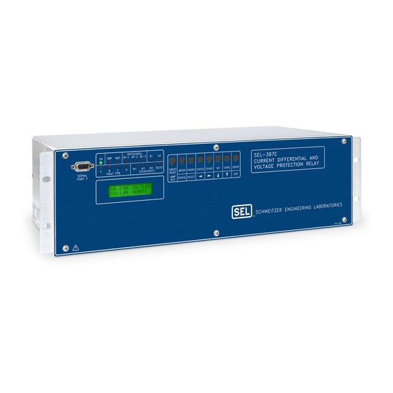
- Page 1 SEL-387E Relay Current Differential and Voltage Protection Relay Instruction Manual 20080110 *PM387E-01-NB*...
- Page 2 Schweitzer Engineering Laboratories, Inc. reserves all rights and benefits afforded under federal and international copyright and patent laws in its products, including without limitation software, firmware, and documentation. The information in this manual is provided for informational use only and is subject to change without notice. Schweitzer Engineering Laboratories, Inc. has approved only the English language manual.
- Page 3 Appendix D: Configuration, Fast Meter, and Fast Operate Commands Appendix E: Compressed ASCII Commands Appendix F: Unsolicited SER Protocol Appendix G: Distributed Network Protocol (DNP3) Appendix H: IEC 61850 Communications SECTION 12: SEL-387E RELAY COMMAND SUMMARY Date Code 20080110 Table of Contents SEL-387E Instruction Manual...
-
Page 5: Table Of Contents
Harmonic Element ........................1-9 Instantaneous/Definite-Time Overcurrent Elements (Winding) ..........1-9 Time Overcurrent Elements (Winding and Combined Current) ..........1-9 Over-/Undervoltage Elements ....................1-10 Frequency Element ......................1-10 Volts/Hertz Element ......................1-10 FIGURES Figure 1.1: SEL-387E Relay Functional Overview ................1-2 Date Code 20080110 Introduction and Specifications SEL-387E Instruction Manual... -
Page 7: Introduction And Specifications
ANUAL VERVIEW This instruction manual applies to the SEL-387E Relay. If you are unfamiliar with this relay, we suggest that you read the following sections in the outlined order. Section 1: Introduction and Specifications for an introduction, instruction manual overview, relay functional overview, and specifications. -
Page 8: Relay Functions
Figure 1.1: SEL-387E Relay Functional Overview Current Differential Protection The SEL-387E Relay includes independent restrained and unrestrained current differential elements. The restrained element has a dual-slope, variable-percentage restraint characteristic. Use the fifth-harmonic element to prevent relay misoperation during allowable overexcitation conditions. -
Page 9: Restricted Earth Fault Protection
Restricted Earth Fault Protection The SEL-387E Relay provides sensitive detection of internal ground faults via the Restricted Earth Fault (REF) protection element. The Winding 3 inputs are used for introduction of neutral CT polarizing current. Operating current is derived from the residual current calculated for the protected winding. -
Page 10: Frequency Protection
Thermal stress from fault currents damages insulation. The SEL-387E Relay provides a through- fault event monitor to gather fault current level, duration, and date/time for each through fault. -
Page 11: Specifications
24 V 0.75 A L/R = 40 ms 48 V 0.50 A L/R = 40 ms 125 V 0.30 A L/R = 40 ms 250 V 0.20 A L/R = 40 ms Date Code 20080110 Introduction and Specifications SEL-387E Instruction Manual... - Page 12 Telnet to Host: 1 server session (supports SEL ASCII, SEL Compressed ASCII, Fast Meter, and Fast Operate) IEC 61850: 6 MMS sessions 16 incoming GOOSE messages 8 outgoing GOOSE messages Protocol Stacks TCP/IP Introduction and Specifications Date Code 20080110 SEL-387E Instruction Manual...
- Page 13 IEC 60255-22-3 [IEC 255-22-3]:1989, ENV 50140:1993, IEEE C37.90.2-1995, 35 V/m, no keying test, frequency element accurate to 0.1 Hz Fast Transient Disturbance: IEC 60255-22-4 [IEC 255-22-4]:1992, IEC 61000-4-4 [IEC 1000-4-4]:1995 Level 4 Date Code 20080110 Introduction and Specifications SEL-387E Instruction Manual...
-
Page 14: Metering Accuracy
1 A Model: ±5% ±0.02 A Unrestrained Element Pickup Time (Min/Typ/Max): 0.8/1.0/1.9 cycles Restrained Element (with harmonic blocking) Pickup Time (Min/Typ/Max): 1.5/1.6/2.2 cycles Restrained Element (with harmonic restraint) Pickup Time (Min/Typ/Max): 2.62/2.72/2.86 cycles Introduction and Specifications Date Code 20080110 SEL-387E Instruction Manual... -
Page 15: Harmonic Element
C2 = IEC Class B (Very Inverse) C3 = IEC Class C (Extremely Inverse) C4 = IEC Long-Time Inverse C5 = IEC Short-Time Inverse Time-Dial Range US Curves: 0.50–15.00 IEC Curves: 0.05–1.00 Date Code 20080110 Introduction and Specifications SEL-387E Instruction Manual... -
Page 16: Over-/Undervoltage Elements
Combination of Definite-Time and Inverse-Time specifications User-Definable Curve Element Pickup Range: 100–200% Steady-State Pickup Accuracy: ±1% of setpoint Pickup Time: 25 ms @ 60 Hz (Max) Reset Time Range: 0.00–400.00 s 1-10 Introduction and Specifications Date Code 20080110 SEL-387E Instruction Manual... - Page 17 Low-Level Analog Interface..................2-19 Clock Battery ......................2-19 Additional Interface Board ....................2-20 Jumpers ........................2-20 Board Layout.......................2-20 TABLES Table 2.1: SEL-387E Relay Communication Cable Numbers ...............2-13 Table 2.2: SEL-387E Relay Second ALARM Contact Jumper Position ..........2-18 Date Code 20080110 Installation SEL-387E Instruction Manual...
- Page 18 Figure 2.4: Rear Panel Drawings–Models 0387Ex0xxxxX and 0387Ex1xxxx2 ........2-6 Figure 2.5: Rear-Panel Drawings–Models 0387Ex1xxxx4 and 0387Ex1xxxx6........2-7 Figure 2.6: Rear-Panel Drawings–Models 0387ExYxxxx2 and 0387ExYxxxx6 ........2-8 Figure 2.7: SEL-387E Relay 3U Typical Rear-Panel Drawings Showing 10/100BASE-T and 100BASE FX Ethernet ....................2-9 Figure 2.8: Standard Independent Output Contact Representation ............2-12 Figure 2.9: Example AC Connections (three-winding transformer;...
-
Page 19: Installation
OUNTING Rack Mount We offer the SEL-387E Relay in a rack-mount version that bolts easily into a standard 19-inch rack. See Figure 2.1. From the front of the relay, insert four rack screws (two on each side) through the holes on the relay mounting flanges. -
Page 20: Dimensions And Cutout
Dimensions and Cutout Figure 2.1: Relay Dimensions and Panel-Mount Cutout Installation Date Code 20080110 SEL-387E Instruction Manual... - Page 21 Figure 2.2: Front-Panel Drawings–Models 0387Ex0xxxH and 0387Ex1xxxH Date Code 20080110 Installation SEL-387E Instruction Manual...
- Page 22 Figure 2.3: Front-Panel Drawings–Models 0387Ex0xxx3 and 0387Ex1xxx3 Installation Date Code 20080110 SEL-387E Instruction Manual...
-
Page 23: Rear-Panel Connections
Connectorized To use the Connectorized version of the SEL-387E Relay, ask your SEL sales or customer service representative for the appropriate model option table and order wiring harness kit WA0387E0YxxxA, where x designates wire sizes and length. You can find the model option table on the SEL Web site at http://www.selinc.com. - Page 24 Figure 2.4: Rear Panel Drawings–Models 0387Ex0xxxxX and 0387Ex1xxxx2 Installation Date Code 20080110 SEL-387E Instruction Manual...
- Page 25 Figure 2.5: Rear-Panel Drawings–Models 0387Ex1xxxx4 and 0387Ex1xxxx6 Date Code 20080110 Installation SEL-387E Instruction Manual...
- Page 26 Figure 2.6: Rear-Panel Drawings–Models 0387ExYxxxx2 and 0387ExYxxxx6 Installation Date Code 20080110 SEL-387E Instruction Manual...
- Page 27 Figure 2.7: SEL-387E Relay 3U Typical Rear-Panel Drawings Showing 10/100BASE-T and 100BASE-FX Ethernet Date Code 20080110 Installation SEL-387E Instruction Manual...
-
Page 28: Prewired Connectors
Connections Frame Ground For safety and performance, ground the relay chassis at terminal GND (Z27). Connectorized relays provide a 0.250-inch-by-0.023-inch spade connector for this connection. If the tab on the 2-10 Installation Date Code 20080110 SEL-387E Instruction Manual... -
Page 29: Current Transformer Inputs
General Specifications in Section 1: Introduction and Specifications for optoisolated input ratings. There are no internal connections between inputs. ON and OFF values normally are within one volt of each other, in the indicated range. Date Code 20080110 Installation 2-11 SEL-387E Instruction Manual... -
Page 30: Output Contacts
For example, to connect the SEL-387E Relay Ports 2, 3, or 4 to the 9-pin male connector on a laptop computer, order cable number C234A and specify the length needed. Standard length is eight feet. -
Page 31: Clock Synchronization, Irig-B
Refer to Table 2.1 for a list of cables that you can purchase from SEL for various time- synchronizing applications. The SEL-387E Relay accepts a demodulated IRIG-B format signal for synchronizing an internal clock to some external source such as the SEL-2032, SEL-2030, or SEL-2020 Communications Processor, SEL-IDM, or satellite time clock. - Page 32 This example forms the basis for most of the factory default settings stored in the relay before shipment. Figure 2.9: Example AC Connections (three-winding transformer; wye-connected voltages) Figure 2.10: Example AC Connections (three-winding transformer; open-delta-connected voltages) 2-14 Installation Date Code 20080110 SEL-387E Instruction Manual...
- Page 33 Figure 2.11: Example AC Connections (two-winding transformer; REF with LV compensated earthing; wye-connected voltages) Figure 2.12: Example AC Connections (two-winding transformer; HV REF; wye- connected voltages) Date Code 20080110 Installation 2-15 SEL-387E Instruction Manual...
-
Page 34: Circuit Board Configuration
4. Each circuit board corresponds to a row of rear-panel terminal blocks or connectors and is affixed to a draw-out tray. Identify which draw-out tray needs to be removed. An SEL-387E 2-16 Installation... -
Page 35: Main Board
Table 2.2 to understand the relationship between the jumper and output contact. The jumper JMP23 controls the operation of output contact OUT107. JMP23 provides the option of a second alarm output contact by changing the signal that drives output contact OUT107. Date Code 20080110 Installation 2-17 SEL-387E Instruction Manual... -
Page 36: Password And Breaker Jumpers
Table 2.2: SEL-387E Relay Second ALARM Contact Jumper Position JMP23 Position Output Contact OUT107 Operation Bottom Second Alarm output contact (operated by alarm logic/circuitry). (Pins 1 & 2) Relay Word bit OUT107 has no effect on output contact OUT107 when jumper JMP23 is in this position. -
Page 37: Condition Of Acceptability For North American Product Safety
Low-Level Analog Interface SEL designed the SEL-387E Relay main board to accept low-level analog signals as an optional testing method. Section 10: Testing and Troubleshooting contains a more detailed discussion of the patented Low-Level Test Interface; and Figure 10.1 shows the pin configuration. The SEL-RTS (Relay Test System) interfaces with the relay through a ribbon cable connection on the main board. -
Page 38: Additional Interface Board
Communications or Section 8: Front-Panel Operation). Additional Interface Board We offer versions of the SEL-387E Relay in a taller case size (3U) to accommodate one additional circuit board. The additional board mounts below the main board and above the analog input (transformer) board. - Page 39 Figure 2.14: Main Board Jumpers, Connections, and Battery Locations Date Code 20080110 Installation 2-21 SEL-387E Instruction Manual...
- Page 40 Figure 2.15: Interface Board 2 Component Layout (Conventional Terminal Block) 2-22 Installation Date Code 20080110 SEL-387E Instruction Manual...
- Page 41 Figure 2.16: Interface Board 4 Component Layout (Conventional Terminal Block) Date Code 20080110 Installation 2-23 SEL-387E Instruction Manual...
- Page 42 Figure 2.17: Interface Board 6 Component Layout (Conventional Terminal Block) 2-24 Installation Date Code 20080110 SEL-387E Instruction Manual...
- Page 43 Figure 2.18: Interface Board 2 Component Layout (Connectorized) Date Code 20080110 Installation 2-25 SEL-387E Instruction Manual...
- Page 44 Figure 2.19: Interface Board 6 Component Layout (Connectorized) 2-26 Installation Date Code 20080110 SEL-387E Instruction Manual...
- Page 45 Example 2 for WnCTC Selection................3-20 Winding Line-to-Line Voltages ..................3-22 Current TAP ........................3-22 Restrained Element Operating Current Pickup ............3-22 Restraint Slope Percentage..................3-23 Unrestrained Element Current Pickup.................3-23 Second-Harmonic Blocking ..................3-24 Fourth-Harmonic Blocking ..................3-24 Fifth-Harmonic Blocking ....................3-24 Date Code 20080110 Protection Functions SEL-387E Instruction Manual...
- Page 46 Independent Harmonic Blocking Element (IHBL) ............3-24 Example of Setting the SEL-387E Relay for a Three-Winding Transformer .....3-25 Application Guidelines .......................3-27 CT Arrangements ......................3-27 CT Sizing ........................3-27 CT Ratio Selection for a Multiwinding Transformer..........3-27 Restricted Earth Fault Element ....................3-28 Application Description ......................3-28 Operating Characteristic .....................3-28...
- Page 47 When 24CCS = DD:....................3-65 When 24CCS = ID: .....................3-66 When 24CCS = I: ....................3-66 When 24CCS = U:....................3-67 When 24CCS = DD, ID, I, or U: .................3-67 Volts/Hertz Setting Reference Information ................3-68 Date Code 20080110 Protection Functions SEL-387E Instruction Manual...
- Page 48 Figure 3.40: Composite Inverse/Definite-Time Overexcitation Characteristic, 24CCS=ID ....3-63 Figure 3.41: Volts/Hertz Inverse-Time Characteristic, 24IC = 0.5............3-68 Figure 3.42: Volts/Hertz Inverse-Time Characteristic, 24IC = 1............3-69 Figure 3.43: Volts/Hertz Inverse-Time Characteristics, 24IC = 2 ............3-70 Protection Functions Date Code 20080110 SEL-387E Instruction Manual...
-
Page 49: Protection Functions
Characteristic Operating The SEL-387E Relay has three differential elements (87R-1, 87R-2, and 87R-3). These elements employ Operate (IOP) and Restraint (IRT) quantities that the relay calculates from the winding input currents. Figure 3.1 shows the relay characteristic. You can set the characteristic as either a single-slope, percentage differential characteristic or as a dual-slope, variable-percentage differential characteristic. - Page 50 Winding 1. The dc, fourth-harmonic, and fifth-harmonic compensated currents use similar names. The I1 compensated currents are used with differential element 87-1, I2 with element 87-2, and I3 with element 87-3. Protection Functions Date Code 20080110 SEL-387E Instruction Manual...
- Page 51 For a through-current condition, this will calculate to about (| 1 | + | –1 |) / 2 = 2 / 2 = 1, at rated load. Date Code 20080110 Protection Functions SEL-387E Instruction Manual...
- Page 52 In element 87Rn, for example, the IOPn and IRTn quantities determine whether the relay trips. The logic enclosed within the dotted line of Figure 3.4 implements the Figure 3.1 characteristic. The differential element calculates a threshold as a function of IRTn. IOPn must exceed this Protection Functions Date Code 20080110 SEL-387E Instruction Manual...
-
Page 53: Harmonic Restraint
Slope 1, i.e., a straight line through the origin. The general equation for a line is: x • More specifically, in the SEL-387E Relay: • 1 Because the line starts at the origin, the value of c is normally zero. The sum of the second- and fourth-harmonic currents now forms the constant c in the equation, raising the relay characteristic proportionally to the harmonic values. -
Page 54: Blocking
Harmonic Blocking Figure 3.6 shows how the 87BL1 blocking element will pick up if the second-, fourth-, or fifth- harmonic operating current, as a percentage of fundamental operating current, is above the 2PCT, Protection Functions Date Code 20080110 SEL-387E Instruction Manual... -
Page 55: Dc Ratio Blocking
The dc ratio blocking feature applies to inrush cases with little harmonic content, but a high dc offset. The measurement principle is that of wave shape recognition, distinguishing between the time constants for inrush current that typically are longer than the time constants for an internal fault. Date Code 20080110 Protection Functions SEL-387E Instruction Manual... -
Page 56: Setting Descriptions
Range: Y, N, Y1 The SEL-387E Relay has three sets of three-phase current inputs. Depending on the application, you may not need all of these inputs for the differential zone of protection. You can configure any unused terminals for stand-alone overcurrent protection. The E87Wn setting specifies which of the terminals the relay is to include in the differential calculation. -
Page 57: Ct Ratio (Ctr1 Through Ctr3)
For delta-connected CTs, the secondary currents into the SEL-387E Relay current inputs are phase-phase difference currents (e.g., phase-phase difference current I – I flows into current input IAWn). To create a pseudo phase-neutral value for display or use in algorithms, these phase-phase difference currents are divided by √3 (divided by 1.732). -
Page 58: Restrained Element Operating Current Pickup (O87P)
PCT5, or IHBL settings. Thus, you must set the element pickup level high enough so as not to react to large inrush currents. Second-Harmonic Blocking Percentage of Fundamental (PCT2) Range: OFF, 5–100%, in 1% steps 3-10 Protection Functions Date Code 20080110 SEL-387E Instruction Manual... -
Page 59: Fourth-Harmonic Blocking Percentage Of Fundamental (Pct4)
The SEL-387E Relay measures the amount of second-harmonic current flowing in the transformer. You can set the relay to block the percentage restrained differential element if the ratio of second-harmonic current to fundamental current (IF2/IF1) is greater than the PCT2 setting. -
Page 60: Fifth-Harmonic Alarm Time Delay Pickup (Th5D)
(HRSTR) settings available. Some magnetizing inrush cases contain very little harmonic content but contain a dc offset. The SEL-387E Relay can detect the dc offset and use it in the blocking (not restraint) logic. Enable this function by setting DCRB = Y. -
Page 61: Setting Calculation
The “0” setting value is intended to create no changes at all in the currents and merely multiplies them by an identity matrix. Thus, for W n CTC = 0, ⎡ ⎤ ⎢ ⎥ ⎢ ⎥ ⎢ ⎥ ⎣ ⎦ Date Code 20080110 Protection Functions 3-13 SEL-387E Instruction Manual... - Page 62 IAWn ICWn IAWnC − IBWn IAWn IBWnC − ICWn IBWn ICWnC The effect of each compensation on balanced three-phase currents is to rotate them m • 30° without a magnitude change. 3-14 Protection Functions Date Code 20080110 SEL-387E Instruction Manual...
-
Page 63: The Complete List Of Compensation Matrices (M = 1 To 12)
− − − ⎤ ⎤ ⎡ ⎡ ⎥ ⎥ ⎢ ⎢ − − − • • ⎥ ⎥ ⎢ ⎢ ⎥ ⎥ ⎢ ⎢ − − − ⎣ ⎦ ⎣ ⎦ Date Code 20080110 Protection Functions 3-15 SEL-387E Instruction Manual... -
Page 64: Selecting The Correct Values Of Wnctc For Each Winding
W n CTC based on system phase rotation. Winding Connection Review Figure 3.8 shows the three basic winding connections, consisting of a wye connection and the two possible delta connections. 3-16 Protection Functions Date Code 20080110 SEL-387E Instruction Manual... - Page 65 B, and C line terminals are, respectively, A-B, B-C, and C-A in terms of the winding currents. In the DAC connection the line currents from the A, B, and C line terminals are, respectively, A-C, Date Code 20080110 Protection Functions 3-17 SEL-387E Instruction Manual...
-
Page 66: Five-Step Compensation Process
CTs. The higher voltage secondary winding has DAB delta-connected CTs. We assume ABC phase rotation. Using the “hour of the clock” convention for specifying transformer connections, the transformer is a “Dy1y9” connection. This means the transformer has a high- 3-18 Protection Functions Date Code 20080110 SEL-387E Instruction Manual... - Page 67 All three windings would then receive adjustments to correlate them with this reference. As Figure 3.9 illustrates, the primary winding direction serves as reference in the example. Date Code 20080110 Protection Functions 3-19 SEL-387E Instruction Manual...
-
Page 68: Example 2 For Wnctc Selection
Figure 3.10 illustrates the second example. This is another three-winding transformer, for which we have chosen rather unusual winding phase relationships in order to show the flexibility of the winding compensation feature in the SEL-387E Relay. The transformer has a 115 kV primary winding that is wye connected, with wye-connected CTs. - Page 69 “noon” reference direction. This procedure requires seven 30-degree increments, or seven “hours” of adjustment. Thus, we choose W2CTC = 7 as the setting. Similarly for Winding 3, we need an adjustment of five “hours,” so we Date Code 20080110 Protection Functions 3-21 SEL-387E Instruction Manual...
-
Page 70: Winding Line-To-Line Voltages
The setting must also yield an operating current greater than or equal to 0.1 • I , when multiplied by the smallest of TAP1 through TAP3. Stated another way, ≥ (0.1 • I O87P ) / TAP 3-22 Protection Functions Date Code 20080110 SEL-387E Instruction Manual... -
Page 71: Restraint Slope Percentage
IHBL settings. Thus, it must be set high enough so as not to react to large inrush currents. Note: U87P must be set lower than 31 • I /TAP , where TAP is the largest of the TAP settings. Date Code 20080110 Protection Functions 3-23 SEL-387E Instruction Manual... -
Page 72: Second-Harmonic Blocking
When a three-phase transformer is energized, inrush harmonics are present in at least two phase currents. In traditional single-phase relays, each relay performs a comparison of the harmonic current flowing through its phase. The SEL-387E Relay can perform harmonic blocking two ways:... -
Page 73: Example Of Setting The Sel-387E Relay For A Three-Winding Transformer
Example of Setting the SEL-387E Relay for a Three-Winding Transformer In this section we use an example that forms the basis of the default differential settings we entered at the factory before shipping the relay. - Page 74 CT saturation on external high-current faults. The settings are as follows: O87P (Operate current pickup in multiple of tap) SLP1 (25 percent initial slope) 3-26 Protection Functions Date Code 20080110 SEL-387E Instruction Manual...
-
Page 75: Application Guidelines
Application of Current Transformers Used for Protective Relaying Purposes. CT Arrangements Use separate relay restraint circuits for each power source to the relay. In the SEL-387E Relay you may apply two to four restraint inputs to the relay. You may connect CT secondary windings in parallel only if both circuits meet the following criteria: •... -
Page 76: Restricted Earth Fault Element
MVA of the particular winding. If this rating is much smaller than the rating of the largest winding, you may violate the tap ratio limit for the SEL-387E Relay (see steps 4 and 5). As before, for wye-connected CTs I equals I . - Page 77 The REF implementation in the SEL-387E Relay uses a directional element (32I) that compares the direction of an operating current, derived from the line-end CTs, with the polarizing current, obtained from the neutral CT. A zero-sequence current threshold and positive-sequence restraint supervise tripping.
- Page 78 TR n , as appropriate. If you want additional security, the relay is programmed to use 32IF to torque control an inverse-time curve for delayed tripping, as discussed below. Figure 3.13 shows the output of the REF protection function. Timing is on an extremely inverse- 3-30 Protection Functions Date Code 20080110 SEL-387E Instruction Manual...
-
Page 79: Setting Descriptions
The setting 32IOP tells the relay which winding or combination of windings it should use in calculating residual current, which acts as the Operate quantity for the directional element. Positive-Sequence Current Restraint Factor, I0/I1 (a0) Range: 0.02–0.50, in 0.01 steps Date Code 20080110 Protection Functions 3-31 SEL-387E Instruction Manual... -
Page 80: Residual Current Sensitivity Threshold (50Gp)
1 for load imbalance. The second criterion relates to the relative sensitivity of the winding CTs compared to the neutral CT. Setting Calculation Operating Quantity Figure 3.14 depicts how to determine the Operate quantity, 32IOP, setting. 3-32 Protection Functions Date Code 20080110 SEL-387E Instruction Manual... - Page 81 For the neutral CT connection, the relay uses only one of the three ABC inputs, e.g., IBW3, so the residual current for input 3 would be IRW3 = 0 + IBW3 + 0 = IBW3. Date Code 20080110 Protection Functions 3-33 SEL-387E Instruction Manual...
-
Page 82: Residual Current Sensitivity Threshold
Operating Characteristic Each winding input of the SEL-387E Relay has 11 overcurrent elements (see Table 3.1). Nine of these 11 are torque-controlled elements, of which there are one definite-time element, one instantaneous element, and one inverse-time element per each of three categories. -
Page 83: 50Pn1 - Phase Definite-Time Element
50P n 1 bit remains asserted for the duration of 50P n 1D. When 50P n 1 deasserts, the timer resets without delay, along with 50P n 1T if it has asserted. Date Code 20080110 Protection Functions 3-35 SEL-387E Instruction Manual... -
Page 84: 50Pn2 - Phase Instantaneous Element
Relay Word bit, 50A n 3(4), 50B n 3(4), or 50C n 3(4). These bits enter an OR gate to assert Relay Word bit 50P n 3(4), indicating “any phase” pickup. 3-36 Protection Functions Date Code 20080110 SEL-387E Instruction Manual... -
Page 85: 51Pn - Phase Inverse-Time Element
The phase inverse-time curve looks at all three phase current magnitudes and times on the basis of the greatest current of the three. It updates this maximum phase current selection every quarter-cycle. Date Code 20080110 Protection Functions 3-37 SEL-387E Instruction Manual... -
Page 86: 50Qn1 And 50Nn1 - Sequence Current Definite-Time Element Logic
Relay Word bit, 50N n 1T, asserts. The 50N n 1T bit asserts only if the 50N n 1 bit remains asserted for the duration of 50N n 1D. When 50N n 1 deasserts, the timer resets without delay, along with 50N n 1T if it has asserted. 3-38 Protection Functions Date Code 20080110 SEL-387E Instruction Manual... -
Page 87: 50Qn2 And 50Nn2 - Sequence Instantaneous Element Logic
51Qn and 51Nn – Sequence Inverse-Time Elements Figure 3.21 shows the logic for the inverse-time 51Q n negative-sequence element and the instantaneous 51N n residual element. Figure 3.21: 51Qn and 51Nn Sequence Inverse-Time O/C Element, Torque Controlled Date Code 20080110 Protection Functions 3-39 SEL-387E Instruction Manual... -
Page 88: 51Qn Negative-Sequence Inverse-Time Element
51PC1 and 51NC1 Combined Overcurrent Elements The combined overcurrent elements operate on summed input currents to two windings. Elements 51PC1 and 51NC1 use phase and residual current from Windings 1 and 2. See Figure 3.22. 3-40 Protection Functions Date Code 20080110 SEL-387E Instruction Manual... -
Page 89: 51Pc1 And 51Nc1 Element Logic
1200 A 3800 A DWG: M387E069 Figure 3.22: Combined Overcurrent Example 51PC1 and 51NC1 Element Logic The logic for the inverse-time combined overcurrent elements 51PC1 and 51NC1 is shown in Figure 3.23. Date Code 20080110 Protection Functions 3-41 SEL-387E Instruction Manual... - Page 90 I n W2 1000 A (primary) Pickup = 8000 A (primary) where n = Phase A, Phase B, or Phase C. Then, converting the observed primary values to secondary values, we have 3-42 Protection Functions Date Code 20080110 SEL-387E Instruction Manual...
- Page 91 You can use the Level 2 serial port command RES or the front-panel RESET51 function under the OTHER button to force the bit to 1 during element testing. This saves time if you have chosen electromechanical reset. Date Code 20080110 Protection Functions 3-43 SEL-387E Instruction Manual...
- Page 92 ° ∠ ° Note: Because CTR1<CTR2, the relay uses CTR2 as the common base. secondary The combined secondary current value is less than the 51NC1P setting, so 51NC1 does not assert. 3-44 Protection Functions Date Code 20080110 SEL-387E Instruction Manual...
- Page 93 51NC1 deasserts and the element resets according to the setting 51NC1RS. At the completion of the reset, Relay Word bit 51NC1R asserts. This bit normally will be at logic state Date Code 20080110 Protection Functions 3-45 SEL-387E Instruction Manual...
-
Page 94: Setting Descriptions
Definite-Time Element Delays (50Pn1D, 50Qn1D, 50Nn1D) Range: 0–16000 cycles, in 0.25-cycle steps Select a time in cycles that you want definite-time elements to wait before asserting. 3-46 Protection Functions Date Code 20080110 SEL-387E Instruction Manual... -
Page 95: Inverse-Time Element Pickups (51Pnp, 51Qnp, 51Nnp, 51Pc1P, 51Nc1P)
OGIC Application Guidelines Transformer Overcurrent Protection Instantaneous overcurrent elements typically provide high-speed protection for high-current, internal transformer faults and coordinated backup protection for faults on the adjacent bus and/or Date Code 20080110 Protection Functions 3-47 SEL-387E Instruction Manual... -
Page 96: Overcurrent Element Operating Quantities
Where the SEL-387E Relay is applied to a distribution substation transformer serving load centers, expected load conditions include steady-state load as well as transient conditions caused by hot and cold load pickup. -
Page 97: Time-Overcurrent Element Settings
Time-Overcurrent Element Settings The SEL-387E Relay includes time-overcurrent elements for phase, negative-sequence, and residual current. Each element operates using measured current and five settings that define: • Pickup current, in secondary amperes •... -
Page 98: Time-Overcurrent Pickup
51 xn RS ( x = P, Q, or N; n = winding number) setting equal to Y. With this setting, the relay emulates the spring-torque-governed disk reset action of an induction time- overcurrent unit. Make this setting when the SEL-387E Relay time-overcurrent element must coordinate with upstream electromechanical time-overcurrent relays during trip-reclose cycles. -
Page 99: Overcurrent Element External Torque-Control
Overcurrent Element External Torque-Control The SEL-387E Relay allows you to either enable or block selected overcurrent elements using a control equation. You may wish, for example, to control an overcurrent element using OGIC an external contact from a toggle switch, control switch, external directional relay, or recloser. -
Page 100: Time Overcurrent Curve Reference Information
⎥ ⎢ ⎥ • − ⎣ ⎦ ⎣ − ⎦ I.E.C. Short-Time Inverse Curve: C5 ⎡ ⎤ ⎢ ⎥ • ⎣ − ⎦ ⎡ ⎤ • ⎢ ⎥ − ⎣ ⎦ 3-52 Protection Functions Date Code 20080110 SEL-387E Instruction Manual... - Page 101 Figure 3.25: U.S. Inverse Curve: U2 Figure 3.24: U.S. Moderately Inverse Curve: U1 Figure 3.26: U.S. Very Inverse Curve: Figure 3.27: U.S. Extremely Inverse Curve: U4 Date Code 20080110 Protection Functions 3-53 SEL-387E Instruction Manual...
- Page 102 Figure 3.29: I.E.C. Class A Curve Figure 3.28: U.S. Short-Time Inverse Curve: (Standard Inverse): C1 Figure 3.31: I.E.C. Class C Curve Figure 3.30: I.E.C. Class B Curve (Extremely Inverse): C3 (Very Inverse): C2 3-54 Protection Functions Date Code 20080110 SEL-387E Instruction Manual...
-
Page 103: Over-/Undervoltage Element
Figure 3.32: I.E.C. Long-Time Inverse Curve: C5 Curve: C4 NDERVOLTAGE LEMENT Application Description The SEL-387E Relay offers the following overvoltage and undervoltage elements for protection, indication, and control functions: • Two levels of phase undervoltage • Two levels of phase-to-phase undervoltage •... - Page 104 Setting Bits 59P1P 59P1 59P2P 59P2 |VPP| 59PP1 59PP1 59PP2 59PP2 |VG|=|3V0| 59G1P 59G1 59G2P 59G2 |V2| 59QP |V1| 59V1 59V1P DWG: M387E034 TPVI= Y Figure 3.34: Overvoltage Element Logic Diagram 3-56 Protection Functions Date Code 20080110 SEL-387E Instruction Manual...
-
Page 105: Setting Descriptions
If you do not need any of these elements, set E59 = N. When E59 = N, the relay hides the overvoltage elements and you do not need to enter the pickup settings. Settings DELTA_Y and TPVI also affect whether these elements are available. Date Code 20080110 Protection Functions 3-57 SEL-387E Instruction Manual... -
Page 106: Phase Undervoltage Element Pickups (27Pnp)
Note that n represents one of two pickup levels, 1 or 2. Positive-Sequence Overvoltage Element Pickup (59V1P) Range : OFF, 0.0–100.0 V Set the pickup for the positive-sequence voltage value above which you want the element to assert. 3-58 Protection Functions Date Code 20080110 SEL-387E Instruction Manual... -
Page 107: Definite-Time Characteristic
LEMENT Application Description The SEL-387E Relay provides six levels of over-/underfrequency elements. Each element can operate as an overfrequency or as an underfrequency element, depending on its pickup setting. If the element pickup setting is less than the nominal system frequency setting, NFREQ, the element operates as an underfrequency element, picking up if measured frequency is less than the set point. - Page 108 Figure 3.37: Frequency Element Logic Note: Instantaneous frequency element Relay Word bits 81D1–81D6 should not be used for applications other than testing. 3-60 Protection Functions Date Code 20080110 SEL-387E Instruction Manual...
-
Page 109: Setting Descriptions
Application Description Overexcitation occurs when a transformer magnetic core becomes saturated. When this happens, stray flux is induced in nonlaminated components, causing overheating. In the SEL-387E Relay a volts/hertz element detects overexcitation. The SEL-387E Relay provides a sensitive definite- time volts/hertz element, plus a tripping element with a composite operating time. The relay calculates the present transformer volts/hertz as a percent of nominal, based on the present and nominal voltages and frequencies. - Page 110 Reset Timing 24CCS Settings 24C2T 24D2P1 24ITD 24D2D1 24D2P2 24CR 24IP 24D2D2 24IC 24CR 24D2D1 24D2D2 24D2D2 V/Hz V/Hz V/Hz 24CCS=U 24CCS=DD 24CCS=ID 24CCS=I DWG: M387E059 Figure 3.38: Volts/Hertz Element Logic Diagram 3-62 Protection Functions Date Code 20080110 SEL-387E Instruction Manual...
- Page 111 Transformer Limit Curve on Generator Voltage Base Generator Manufacturer's Recommended Protection Curve 24D2P2=118% 24D2D2=1.2 s Relay Characteristic 24IP=108% .001 1000 Time (Minutes) DWG: M300G044 Figure 3.40: Composite Inverse/Definite-Time Overexcitation Characteristic, 24CCS=ID Date Code 20080110 Protection Functions 3-63 SEL-387E Instruction Manual...
-
Page 112: Setting Descriptions
LV sides in wye, leaving the power transformer winding connections as the only variable. For wye-connected power transformer windings, the power transformer phase-to-neutral voltage is readily measured through wye-wye connected PTs. Set 24WDG = Y. When the power 3-64 Protection Functions Date Code 20080110 SEL-387E Instruction Manual... -
Page 113: Level 1 Volts/Hertz Element Pickup (24D1P)
Level 2 Pickups (24D2P1 and 24D2P2) Range : 100–200% (for 24D2P1) Range : 101–200% (for 24D2P2) The SEL-387E Relay asserts the 24C2 Relay Word bit without time delay when the transformer volts/hertz exceeds either the 24D2P1 or 24D2P2 setting. Level 2 Time-Delays (24D2D1 and 24D2D2) Range : 0.04–400.00 s... -
Page 114: When 24Ccs = Id
Range : 100–200% The 24IP setting defines the pickup point of the inverse-time portion of the operating time curve. The SEL-387E Relay asserts the 24C2 Relay Word bit without time delay when the transformer volts/hertz exceeds the 24IP setting. Level 2 Inverse-Time Curve (24IC) Range : 0.5, 1.0, 2.0... -
Page 115: When 24Ccs = U
The 24IP setting defines the pickup point of the user-defined operating time curve. The SEL-387E Relay asserts the 24C2 Relay Word bit without time delay when the transformer volts/hertz exceeds the 24IP setting. The relay asserts the 24C2T Relay Word bit in time defined by the user-defined curve when the measured apparatus volts/hertz exceeds the user-defined setting. -
Page 116: Volts/Hertz Setting Reference Information
• ⎜ ⎟ ⎜ ⎟ ⋅ freq ⎝ VNOM ⎠ ⎜ ⎟ − ⎜ ⎟ ⎜ ⎟ ⎜ ⎜ ⎟ ⎟ ⎝ ⎠ Figure 3.41: Volts/Hertz Inverse-Time Characteristic, 24IC = 0.5 3-68 Protection Functions Date Code 20080110 SEL-387E Instruction Manual... - Page 117 • ⎜ ⎟ ⎜ ⎟ ⋅ freq ⎝ VNOM ⎠ ⎜ ⎟ − ⎜ ⎟ ⎜ ⎟ ⎜ ⎜ ⎟ ⎟ ⎝ ⎠ Figure 3.42: Volts/Hertz Inverse-Time Characteristic, 24IC = 1 Date Code 20080110 Protection Functions 3-69 SEL-387E Instruction Manual...
- Page 118 • ⎜ ⎟ ⎜ ⎟ ⋅ freq VNOM ⎝ ⎠ ⎜ ⎟ − ⎜ ⎟ ⎜ ⎟ ⎜ ⎜ ⎟ ⎟ ⎝ ⎠ Figure 3.43: Volts/Hertz Inverse-Time Characteristics, 24IC = 2 3-70 Protection Functions Date Code 20080110 SEL-387E Instruction Manual...
- Page 119 LED 8 – 24 – Volts-per-Hertz Element ................4-15 LED 9 – A – A-Phase Involved in the Fault (Programmable LEDA)........4-15 LED 10 – B – B-Phase Involved in the Fault (Programmable LEDB).......4-16 Date Code 20080110 Control Logic SEL-387E Instruction Manual...
- Page 120 OGIC Table 4.7: Maximums for SEL Control Equations.................4-25 OGIC Table 4.8: SEL-387E Relay Word Bits and Locations................4-26 Table 4.9: Relay Word Bit Definitions....................4-27 Table 4.10: Relay Word Bits Sorted Alphabetically ................4-39 FIGURES Figure 4.1: Remote Control Switches Drive Remote Bits RB1 Through RB16 ........4-2 Figure 4.2: Rotating Selector Switch for Active Setting Group Selection..........4-6...
-
Page 121: Control Logic
Optoisolated inputs receive their function by how their corresponding Relay Word bits are used in SEL control equations. Remember that any input Relay Word bit name will always OGIC appear on the right side of any SEL control equation, as shown below. OGIC Date Code 20080110 Control Logic SEL-387E Instruction Manual... -
Page 122: Factory Settings Examples
Operate the 16 local control switches using the front-panel keyboard/display (see Section 8: Front-Panel Operation). EMOTE ONTROL WITCHES Remote control switches are operated via the serial communications port only (see Section 7: Communications). Figure 4.1: Remote Control Switches Drive Remote Bits RB1 Through RB16 Control Logic Date Code 20080110 SEL-387E Instruction Manual... -
Page 123: Remote Bit Application
Global settings area (SHO G/SET G commands). Active Setting Group Indication Only one setting group can be active at a time. Relay Word bits SG1 through SG6 indicate the active setting group: Date Code 20080110 Control Logic SEL-387E Instruction Manual... -
Page 124: Selecting The Active Setting Group
With Setting Group 3 as the active setting group, if setting SS3 is deasserted to logical 0 and one of the other settings (e.g., setting SS5) asserts to logical 1, the relay switches from Setting Control Logic Date Code 20080110 SEL-387E Instruction Manual... -
Page 125: Operation Of Serial Port Group Command And Front-Panel Group Pushbutton
Group 3 Group 4 Group 5 Group 6 The SEL-387E Relay can be programmed to operate similarly. Use three optoisolated inputs to switch between the six setting groups in the SEL-387E Relay. In this example optoisolated Date Code 20080110 Control Logic... - Page 126 For example, in rotating from position 1 to position 5, the switch must pass through positions 2, 3, and 4. It should not remain in 2, 3, or 4 for longer Control Logic Date Code 20080110 SEL-387E Instruction Manual...
-
Page 127: Chsg Relay Word Bit Asserts During Setting Group Changes
The active setting group is retained if power to the relay is lost and then restored. If a particular setting group is active (e.g., Setting Group 5) when power is lost, it comes back with the same setting group active when power is restored. Date Code 20080110 Control Logic SEL-387E Instruction Manual... -
Page 128: Note: Make Active Setting Group Switching Settings With Care
OGIC constructing control equations. In the SEL-387E these variables are of two types: timed variables and latch bits. The variables are processed in the order in which they appear in the Settings Sheets. If variables that appear earlier are used as inputs to later variables, the processing of both will occur within the same processing interval. -
Page 129: Variables/Timers
SnVmDO load up again after power restoration, settings change, or active setting group switch. Latch Control Switches The SEL control equations latch bit feature of this relay replaces latching relays. OGIC Traditional latching relays maintain their output contact state—they are not dependent on dc Date Code 20080110 Control Logic SEL-387E Instruction Manual... - Page 130 (e.g., SCADA, RTU, etc.). Figure 4.4: Traditional Latching Relay The latch bits in the SEL-387E Relay provide latching relay type functions (Figure 4.5). Figure 4.5: Latch Bits in SEL Control Equation Sets OGIC The output of the latch bit logic is a Relay Word bit SnLTm.
-
Page 131: Latch Bit Behavior For Power Loss, Settings Change, Active Group Change
The net effect is that the latch bits in the SEL-387E Relay behave exactly like traditional latching relays. Note: Make Latch Bit Settings With Care The latch bit states are stored in nonvolatile memory so they can be retained during power loss, settings change, or active setting group change. -
Page 132: Operation Of Output Contacts For Different Output Contact Types
The Relay Word bit NOTALM (not ALARM) is asserted to logical 1, and the ALARM output contact coil is energized, when the SEL-387E Relay is operating correctly. When the serial port command PULSE NOTALM (or front-panel CNTRL ALARM) is executed, the NOTALM Relay Word bit momentarily deasserts to logical 0. -
Page 133: Rotating Default Display
ARGETING OGIC The SEL-387E Relay has 16 LEDs on the front panel. One (EN) is dedicated to indication of the relay’s operational condition. Twelve are dedicated to specific targeting functions. Three (LEDA, LEDB, and LEDC) have default targeting logic, but are fully programmable by the user. -
Page 134: Led 1 - En - Relay Enabled
If so, the 87E1 bit is also set. LED 4 remains lit until reset by the TRGTR element. TRGTR is asserted for one cycle either via the TARGET RESET pushbutton on the front panel or via the serial port command TAR R. 4-14 Control Logic Date Code 20080110 SEL-387E Instruction Manual... -
Page 135: Led 5 - 87-2 - Differential Element 2
IAWn phase current is greater than or equal to the magnitudes of IBWn and ICWn. Relay Word bit 87E1 indicates differential element 87-1 operation, and follows LED 4 operation (see LED 4 discussion). Date Code 20080110 Control Logic 4-15 SEL-387E Instruction Manual... -
Page 136: Led 10 - B - B-Phase Involved In The Fault (Programmable Ledb)
This LED will illuminate if any Winding 2 overcurrent element present in the TR1 through TR4 settings is asserted at the rising edge of the trip or one cycle later. Applicable elements include 4-16 Control Logic Date Code 20080110 SEL-387E Instruction Manual... -
Page 137: Led 15 - W3 - Winding 3 Overcurrent Element Operation
TARGET RESET pushbutton on the front panel or via the serial port command TAR R. RIP AND LOSE OGIC The trip logic and close logic for the SEL-387E Relay operate in a similar manner. Each has a control equation setting to set or latch the logic and another SEL control equation OGIC OGIC setting to reset or unlatch the logic. - Page 138 Figure 4.7: SEL-387E Relay Trip Logic (TRIP1) The logic begins with the assertion of SEL control equation TR1, one of the Group OGIC variables. In our example application Relay Word bits representing three Winding 1 overcurrent elements and the OPE 1 command are used to assert TR1. TR1 directly asserts TRIP1 via the three-input OR gate at the right.
- Page 139 At the bottom of Figure 4.7 is an additional OR gate. The four TRIPm Relay Word bits are all inputs to this gate, and the output is another Relay Word bit TRIPL. TRIPL asserts for any trip output. It may be useful for other applications of SEL control equations in the SEL-387E OGIC Relay.
-
Page 140: Close Logic
The default setting is 9 cycles. Close Logic There are three specific sets of close logic within the SEL-387E Relay. They are designed to operate when SEL control equation close variable setting CLm is asserted (m = 1, 2, 3) and... - Page 141 52A1 = IN101, 52A2 = IN102, and 52A3 = IN103. (Note again that inputs appear in the right side of an equation, outputs on the left side.) The connections for the 52a inputs are shown in Figure 2.19 in Section 2: Installation. Date Code 20080110 Control Logic 4-21 SEL-387E Instruction Manual...
- Page 142 We intend in this manual to explain how SEL control equations OGIC work in general and how we implement these equations in the SEL-387E Relay. Control Equations Fundamental Description OGIC Relay Word bits are the basic building blocks of SEL control equations.
-
Page 143: Sel Ogic Control Equations
0 or 1. Control Equation Logical Operators OGIC In the SEL-387E Relay, there are six logical operators that can be used in SEL control OGIC equations. These operators exist in a hierarchy, from the highest level operator to be processed to the lowest level operator. -
Page 144: Rising-Edge And Falling-Edge Operators, / And
We could set 51P1TC directly to 0. If 51P1TC = 0, the 51P1 element will never operate. This is one way, for example, to temporarily disable the 51P1 for some operational reason. It could be done using the SET command via a serial port from a remote location. 4-24 Control Logic Date Code 20080110 SEL-387E Instruction Manual... - Page 145 1 (logical 1) or 0 (logical 0) also have OGIC to be included in these limitations—each such setting counts as one element. After SELogic control equation settings have been made and the settings are saved, the SEL-387E Relay responds with the following message: SCEUSE xx.x GRnCHK yyyy This message indicates that xx.x% of the maximum number of Relay Word bits are being used...
-
Page 146: Relay Word Bits
Table 4.9 lists the Relay Word bit definitions, in their row order. Table 4.10 lists the Relay Word bits alphabetically, to provide an easier method for looking for a specific bit. Table 4.8: SEL-387E Relay Word Bits and Locations SEL-387E Relay Word Bits... - Page 147 SEL-387E Relay Word Bits S3V1 S3V2 S3V3 S3V4 S3V5 S3V6 S3V7 S3V8 S3V1T S3V2T S3V3T S3V4T S3V5T S3V6T S3V7T S3V8T S1LT1 S1LT2 S1LT3 S1LT4 S2LT1 S2LT2 S2LT3 S2LT4 S3LT1 S3LT2 S3LT3 S3LT4 S3LT5 S3LT6 S3LT7 S3LT8 50GC 50G3 32IR 32IF...
- Page 148 51P2T Winding 2 phase inverse-time O/C element timed out 51P2R Winding 2 phase inverse-time O/C 51P2 element is reset PDEM2 Winding 2 phase demand current threshold exceeded O/C element B-phase selection 4-28 Control Logic Date Code 20080110 SEL-387E Instruction Manual...
- Page 149 51P3T Winding 3 phase inverse-time O/C element timed out 51P3R Winding 3 phase inverse-time O/C 51P3 element is reset PDEM3 Winding 3 phase demand current threshold exceeded O/C element C-phase selection Date Code 20080110 Control Logic 4-29 SEL-387E Instruction Manual...
- Page 150 Level 2 phase-phase undervoltage picked up 27PP1 Level 1 phase-phase undervoltage picked up 27P2 Level 2 phase undervoltage picked up 27P1 Level 1 phase undervoltage picked up Reserved for future use Current transformer saturation 4-30 Control Logic Date Code 20080110 SEL-387E Instruction Manual...
- Page 151 Unrestrained differential element picked up 87R1 Restrained differential element 1 picked up 87R2 Restrained differential element 2 picked up 87R3 Restrained differential element 3 picked up Restrained differential element picked up Date Code 20080110 Control Logic 4-31 SEL-387E Instruction Manual...
- Page 152 Windings 1 and 2 residual inverse-time O/C element timed out 51NC1R Windings 1 and 2 residual inverse-time O/C element is reset DC battery voltage Level 1 exceeded DC battery voltage Level 2 exceeded 4-32 Control Logic Date Code 20080110 SEL-387E Instruction Manual...
- Page 153 Setting Group 4 is the active setting group Setting Group 5 is the active setting group Setting Group 6 is the active setting group CHSG Timing to change setting groups Reserved for future use Date Code 20080110 Control Logic 4-33 SEL-387E Instruction Manual...
- Page 154 Reserved for future use Reserved for future use Reserved for future use Reserved for future use Reserved for future use Reserved for future use Reserved for future use Reserved for future use 4-34 Control Logic Date Code 20080110 SEL-387E Instruction Manual...
- Page 155 S3V6 timer input asserted OGIC S3V7 Set 3 SEL control equation variable S3V7 timer input asserted OGIC S3V8 Set 3 SEL control equation variable S3V8 timer input asserted OGIC Date Code 20080110 Control Logic 4-35 SEL-387E Instruction Manual...
- Page 156 Combined residual current sensitivity threshold exceeded 50G3 W3 residual current sensitivity threshold exceeded 32IR 32I element reverse (external) fault declaration 32IF 32I element forward (internal) fault declaration REFP Restricted earth fault inverse-time O/C element timed-out 4-36 Control Logic Date Code 20080110 SEL-387E Instruction Manual...
- Page 157 Reserved for future use CF1T Breaker 1 close failure timer timed out CF2T Breaker 2 close failure timer timed out CF3T Breaker 3 close failure timer timed out Reserved for future use Date Code 20080110 Control Logic 4-37 SEL-387E Instruction Manual...
- Page 158 Output OUT301 asserted OUT302 Output OUT302 asserted OUT303 Output OUT303 asserted OUT304 Output OUT304 asserted OUT305 Output OUT305 asserted OUT306 Output OUT306 asserted OUT307 Output OUT307 asserted OUT308 Output OUT308 asserted 4-38 Control Logic Date Code 20080110 SEL-387E Instruction Manual...
- Page 159 5HB1 Fifth-Harmonic block asserted for differential element 1 5HB2 Fifth-Harmonic block asserted for differential element 2 5HB3 Fifth-Harmonic block asserted for differential element 3 24C2 Level 2 Volts/Hertz composite element pickup Date Code 20080110 Control Logic 4-39 SEL-387E Instruction Manual...
- Page 160 Winding 1 residual instantaneous O/C Level 2 element picked up 50N21 Winding 2 residual definite-time O/C Level 1 element picked up 50N21T Winding 2 residual definite-time O/C Level 1 element timed out 4-40 Control Logic Date Code 20080110 SEL-387E Instruction Manual...
- Page 161 Winding 3 residual inverse-time O/C element picked up 51N3R Winding 3 residual inverse-time O/C 51N3 element is reset 51N3T Winding 3 residual inverse-time O/C element timed out 51NC1 Windings 1 and 2 residual inverse-time O/C element picked up Date Code 20080110 Control Logic 4-41 SEL-387E Instruction Manual...
- Page 162 81D2 Level 2 frequency element 81D3 Level 3 frequency element 81D4 Level 4 frequency element 81D5 Level 5 frequency element 81D6 Level 6 frequency element 81D1T Level 1 definite-time frequency element 4-42 Control Logic Date Code 20080110 SEL-387E Instruction Manual...
- Page 163 BCWC2 C-phase Breaker 2 contact wear threshold exceeded BCWC3 C-phase Breaker 3 contact wear threshold exceeded Breaker 1 CLOSE command execution Breaker 2 CLOSE command execution Breaker 3 CLOSE command execution Date Code 20080110 Control Logic 4-43 SEL-387E Instruction Manual...
- Page 164 Input IN212 asserted IN213 Input IN213 asserted IN214 Input IN214 asserted IN215 Input IN215 asserted IN216 Input IN216 asserted IN301 Input IN301 asserted IN302 Input IN302 asserted IN303 Input IN303 asserted 4-44 Control Logic Date Code 20080110 SEL-387E Instruction Manual...
- Page 165 Winding 2 residual demand current threshold exceeded NDEM3 Winding 3 residual demand current threshold exceeded NOTALM ALARM output not asserted Breaker 1 OPEN command execution Breaker 2 OPEN command execution Breaker 3 OPEN command execution Date Code 20080110 Control Logic 4-45 SEL-387E Instruction Manual...
- Page 166 Output OUT305 asserted OUT306 Output OUT306 asserted OUT307 Output OUT307 asserted OUT308 Output OUT308 asserted OUT309 Output OUT309 asserted OUT310 Output OUT310 asserted OUT311 Output OUT311 asserted OUT312 Output OUT312 asserted 4-46 Control Logic Date Code 20080110 SEL-387E Instruction Manual...
- Page 167 S1V3 timer input asserted OGIC S1V3T Set 1 SEL control equation variable S1V3 timer output asserted OGIC S1V4 Set 1 SEL control equation variable S1V4 timer input asserted OGIC Date Code 20080110 Control Logic 4-47 SEL-387E Instruction Manual...
- Page 168 Set 3 SEL control equation variable S3V8 timer input asserted OGIC S3V8T Set 3 SEL control equation variable S3V8 timer output asserted OGIC Setting Group 1 is the active setting group 4-48 Control Logic Date Code 20080110 SEL-387E Instruction Manual...
- Page 169 Fifth-Harmonic alarm threshold exceeded for longer than TH5D TRGTR Target reset pushbutton/TAR R command TRIP1 Trip 1 logic asserted TRIP2 Trip 2 logic asserted TRIP3 Trip 3 logic asserted TRIP4 Trip 4 logic asserted TRIPL Any trip asserted Date Code 20080110 Control Logic 4-49 SEL-387E Instruction Manual...
- Page 171 Table 5.2: Through-Fault Event Monitor Settings .................5-15 Table 5.3: Self-Test Alarm Limits......................5-21 FIGURES Figure 5.1: SEL-387E Relay Demand Ammeter Functions and Commands ...........5-6 Figure 5.2: Station DC Battery Monitor Alarm Logic ................5-9 Figure 5.3: Undervoltage and Overvoltage Warning and Alarm Regions ..........5-10 Figure 5.4: Trip Bus Sensing With Relay Input ..................5-11...
- Page 172 Figure 5.6: Distribution Feeder Faults Expose Transformer Bank to Through Faults......5-15 Figure 5.7: Through-Fault Triggering, Duration, and Maximum Currents..........5-16 Figure 5.8: Cumulative I t Alarm (Relay Word bit ISQTAL)..............5-17 Metering and Monitoring Date Code 20080110 SEL-387E Instruction Manual...
-
Page 173: Metering And Monitoring
METERING AND MONITORING NTRODUCTION The SEL-387E Relay provides metering information in several report formats, for each of the three three-phase winding current inputs and three voltage inputs, and for the three differential elements. A dc battery monitor reports on the supply voltage to the relay and can be programmed to alarm for voltage excursions. -
Page 174: Demand Ammeter Function (Meter D Command)
=>> Demand Ammeter Function (METER D Command) The SEL-387E Relay includes a thermal demand metering function for all three current windings. In response to the METER D (MET D) command, the individual phase demand currents, as well as the negative-sequence and residual demand currents for each winding, are displayed in primary RMS amperes. -
Page 175: Peak Demand Ammeter Function (Meter P Command)
In response to the METER P ( MET P ) command, the phase current peak demands, as well as the negative-sequence and residual current peak demands for each winding, are displayed in Date Code 20080110 Metering and Monitoring SEL-387E Instruction Manual... -
Page 176: Differential Metering Function (Meter Dif Command)
32767, the report will be repeated m times in succession. In this mode subsequent reports are not generated until the previous report has been completely sent. The format for the METER DIF report is as follows: Metering and Monitoring Date Code 20080110 SEL-387E Instruction Manual... -
Page 177: Phasor Metering Function (Meter Sec Command)
VAWX to an angle of zero degrees. However, if the magnitude of VAWX is less than 0.0975 • V (13 V for a 120 V relay), the angles are listed according to the phasor calculation, without further adjustment. Date Code 20080110 Metering and Monitoring SEL-387E Instruction Manual... -
Page 178: Demand Reset Functions (Meter Rd And Meter Rp Commands)
Residual current demand is compared to NDEM n P, and Relay Word bit NDEM n is set if the threshold is exceeded. Figure 5.1: SEL-387E Relay Demand Ammeter Functions and Commands Metering and Monitoring Date Code 20080110... -
Page 179: Harmonic Metering Function (Meter H Command)
123.12 123.12 123.12 123.12 123.12 123.12 123.12 123.12 123.12 =>> The Analog Input Labels, IAW1, etc., will be listed as they are set in the Global Settings section of the relay. Date Code 20080110 Metering and Monitoring SEL-387E Instruction Manual... -
Page 180: Energy Metering Function (Meter E Command)
Three-phase incoming reactive power Use the METER RE ( MET RE ) to reset the energy data. In response to the METER RE command, the relay displays the following message: Reset Energies (Y/N)? Metering and Monitoring Date Code 20080110 SEL-387E Instruction Manual... -
Page 181: Station Dc Battery Monitor
ATTERY ONITOR Use the station dc battery monitor in the SEL-387E Relay to alarm for undervoltage and overvoltage dc battery conditions and to view how station dc battery voltage fluctuates during tripping, closing, and other dc control functions. The monitor measures station dc battery voltage applied to the rear-panel terminals labeled Z25 (+) and Z26 (–). -
Page 182: Detection Of Voltage Dips In Event Reports
REAKER ONITOR The SEL-387E Relay breaker monitoring function captures information on the number of operations and total interrupted current for as many as three breakers. These data are used to estimate the amount of contact wear per pole, based on wear curve information the user derives from breaker manufacturer maintenance curves and enters into the relay. -
Page 183: Breaker Wear Curve Description And Settings
In order to capture trip information for other Breaker 1 trips initiated by devices other than the SEL-387E Relay, BKMON n must be set to sense these trips. This can be done, for example, by using an input to monitor the trip bus for the given breaker. This is illustrated in Figure 5.4, where IN106 is connected to the Breaker 1 trip bus and asserts for any trip from any source. - Page 184 The two straight line segments of the curve between the three defined points define the number of operations as a function of current in kiloamperes by an equation of the form: α I • 5-12 Metering and Monitoring Date Code 20080110 SEL-387E Instruction Manual...
- Page 185 This can be done via the BRE R n (or BRE n R ) serial port command or from the front panel via the OTHER pushbutton menu. Both the BRE W n and BRE R n commands can be executed from Access Level B or 2. Date Code 20080110 Metering and Monitoring 5-13 SEL-387E Instruction Manual...
-
Page 186: Breaker Wear Example
=>> HROUGH AULT VENT ONITOR Figure 5.6 shows a distribution feeder fault beyond the protection zone of the SEL-387E Relay. Nevertheless, the fault current passes through the transformer bank, subjecting the windings to 5-14 Metering and Monitoring Date Code 20080110... -
Page 187: Through-Fault Event Monitor Settings
Figure 5.6: Distribution Feeder Faults Expose Transformer Bank to Through Faults Monitor and document this through-fault activity with the through-fault event monitor in the SEL-387E Relay. The through-fault event monitor captures maximum current levels, duration, and date/time for each transformer through fault. The monitor also performs a simple I calculation (analogous to the energy expended during the through fault) and cumulatively stores calculation results for each monitored phase. -
Page 188: Through-Fault Calculation
For example, if a through fault is 6000 A primary (maximum) and lasts 0.067 sec., the monitor would calculate I t for that individual event as follows: 5-16 Metering and Monitoring Date Code 20080110 SEL-387E Instruction Manual... -
Page 189: Through-Fault Alarm
Maximum current (Amps primary) for each monitored current input The following cumulative values (updated for each new through-fault event) are also displayed: • Through-fault count • Simple I t calculation for each monitored current input Date Code 20080110 Metering and Monitoring 5-17 SEL-387E Instruction Manual... - Page 190 Winding 1 Total I-squared-t Preload (kA^2 seconds, primary): A-phase = 1.783? 147.8 <Enter> B-phase = 88.270? 303.5 <Enter> C-phase = 6.610? 237.9 <Enter> Are you sure (Y/N) ? Y <Enter> 5-18 Metering and Monitoring Date Code 20080110 SEL-387E Instruction Manual...
-
Page 191: Deriving Cumulative I 2 T Values For Preloading
I calculations and cumulatively storing calculation results for each monitored phase. All these through-fault event data are stored in nonvolatile memory. Date Code 20080110 Metering and Monitoring 5-19 SEL-387E Instruction Manual... -
Page 192: Status Monitor
TATUS ONITOR The status monitor of the SEL-387E Relay is designed to provide information on the internal health of the major components of the relay. The relay continuously runs a variety of self-tests. Some tests have warning and failure states; others only have failure states. - Page 193 IAW3, IBW3, input channels. ICW3, VAWX, VBWX, VCWX, Offset +5 V PS Warning +4.80 V Pulsed Periodically +5.20 V measures the +5 V power supply Failure +4.65 V Latched +5.40 V Date Code 20080110 Metering and Monitoring 5-21 SEL-387E Instruction Manual...
- Page 194 +85°C measures the main board temperature. Failure Latched Periodically performs a read/write test at each RAM location. Failure checksum Latched Periodically performs a checksum test on the relay program memory. 5-22 Metering and Monitoring Date Code 20080110 SEL-387E Instruction Manual...
- Page 195 No Link No link established on Ethernet port. PORT 6 Link Link established on Ethernet port. No Link No link established on Ethernet port. FPGA Failure Pulsed Ensures FPGA configures properly. Date Code 20080110 Metering and Monitoring 5-23 SEL-387E Instruction Manual...
- Page 196 Ethernet port hardware responds and watchdog timer has not expired. DRAM Failure Pulsed Ensures dual port RAM configured properly. Failure Pulsed Continually measures the input voltage supplied from the relay. 5-24 Metering and Monitoring Date Code 20080110 SEL-387E Instruction Manual...
- Page 197 Front-Panel Displays......................6-7 Sequential Events Reporting....................6-7 Communications Ports......................6-8 Default Settings ..........................6-9 SEL-387E Relay SHO G (Show Global Settings)..............6-9 SEL-387E Relay SHO P (Show Port Settings)..............6-10 SEL-387E Relay SHO R (Show SER Settings)..............6-11 SEL-387E Relay Default Settings (5 A)................6-12 SEL-387E Relay Default Settings (1 A)................6-14 Settings Sheets ..........................6-16...
-
Page 199: Settings
See Section 7: Communications for information on serial port communications and relay access levels. The SET commands in Table 6.1 operate at Access Level 2 (screen prompt: =>>). To change a specific setting, enter the command: SET n m s TERSE Date Code 20080110 Settings SEL-387E Instruction Manual... - Page 200 (see Table 6.1), the relay is not disabled while it saves the new settings. The ALARM contact closes momentarily (for a "b" contact, opens for an "a") but the EN LED remains on while the new settings are saved. Settings Date Code 20080110 SEL-387E Instruction Manual...
-
Page 201: Additional Relay Settings
VA. The three-phase power calculation assumes a balanced three-phase system when TPVI=N. The TPVI=N selection supports the V/Hz element when only a single PT is available, connected to the A phase. Date Code 20080110 Settings SEL-387E Instruction Manual... -
Page 202: Demand Ammeter (Datc, Pdem, Qdem, Ndem)
This will yield reports for some external faults that do not result in tripping of the transformer breakers, but for which information might be useful. Winding 3 element pickup is used to detect external tertiary circuit faults that may be too weak to be detected by the Settings Date Code 20080110 SEL-387E Instruction Manual... -
Page 203: System Frequency (Nfreq) And Phase Rotation (Phrot)
System Frequency (NFREQ) and Phase Rotation (PHROT) The relay settings NFREQ and PHROT establish your basic system parameters for the SEL-387E Relay. 1. Set NFREQ equal to the nominal power system operating frequency, either 50 Hz or 60 Hz. -
Page 204: Miscellaneous (Date_F, Scrold, Fp_To, Tgr)
Relay Word elements to describe the triggering conditions for OGIC that particular monitor. When triggered, the monitor measures the three-phase currents 1.5 cycles after triggering, adds them to the total accumulated current for that breaker, and adds one Settings Date Code 20080110 SEL-387E Instruction Manual... -
Page 205: Analog Input Labels
The SER settings are made after issuing the SET R command from a communications port. The SER operation and settings are described fully in Section 9: Analyzing Events. Date Code 20080110 Settings SEL-387E Instruction Manual... -
Page 206: Communications Ports
Communications Ports There are four communications ports and two optional Ethernet ports on the SEL-387E Relay. Port 1 is an EIA-485 port on the rear panel. Ports 2 and 3, also on the rear panel, are EIA-232. Port 4 is an EIA-232 port on the front panel. Ports 5 and 6 are the Ethernet ports on the rear panel. -
Page 207: Sel-387E Relay Sho G (Show Global Settings)
EFAULT ETTINGS SEL-387E Relay SHO G (Show Global Settings) =>>SHO G <Enter> = 15 NFREQ = 60 PHROT = ABC DELTA_Y = Y DATE_F = MDY SCROLD FP_TO = 16 DC1P = OFF DC2P = OFF DC3P = OFF DC4P... -
Page 208: Sel-387E Relay Sho P (Show Port Settings)
Note: SCEUSE is the percent of SEL control equations used in Global settings. GBLCHK OGIC is the Global setting checksum used by the relay's diagnostics. SEL-387E Relay SHO P (Show Port Settings) =>>SHO P <Enter> Port F PROTO = SEL... -
Page 209: Sel-387E Relay Sho R (Show Ser Settings)
SEL-387E Relay SHO R (Show SER Settings) =>>SHO R <Enter> SER1 =IN101,IN102,IN103,IN104,IN105,IN106 SER2 =OUT101,OUT102,OUT103,OUT104,OUT105,OUT106,OUT107 SER3 SER4 ALIAS1 ALIAS2 ALIAS3 ALIAS4 ALIAS5 ALIAS6 ALIAS7 ALIAS8 ALIAS9 ALIAS10 =NA ALIAS11 =NA ALIAS12 =NA ALIAS13 =NA ALIAS14 =NA ALIAS15 =NA ALIAS16 =NA ALIAS17 =NA... -
Page 210: Sel-387E Relay Default Settings (5 A)
SEL-387E Relay Default Settings (5 A) =>>SHO <Enter> Group 1 =XFMR 1 =STATION A E87W1 E87W2 E87W3 EOC1 EOC2 EOC3 EOCC ESLS1 ESLS2 ESLS3 W1CT W2CT W3CT CTR1 = 120 CTR2 = 240 CTR3 = 400 = 100.0 ICOM W1CTC... - Page 211 OUT212 SCEUSE 47.8 GR1CHK 68EB =>> Note: SCEUSE is the percent of SEL control equations used in this setting group. OGIC GRnCHK is the Group setting checksum used by the relay's diagnostics. Date Code 20080110 Settings 6-13 SEL-387E Instruction Manual...
-
Page 212: Sel-387E Relay Default Settings (1 A)
SEL-387E Relay Default Settings (1 A) =>>SHO <Enter> Group 1 =XFMR 1 =STATION A E87W1 E87W2 E87W3 EOC1 EOC2 EOC3 EOCC ESLS1 ESLS2 ESLS3 W1CT W2CT W3CT CTR1 = 600 CTR2 = 1200 CTR3 = 2000 = 100.0 ICOM W1CTC... - Page 213 =/50P11 + /51P1 + /51Q1 + /51P2 + /51Q2 + /51P3 OUT101 =TRIP1 OUT102 =TRIP2 OUT103 =TRIP3 OUT104 =TRIP4 OUT105 =CLS1 OUT106 =CLS2 OUT107 =CLS3 OUT201 OUT202 OUT203 OUT204 OUT205 OUT206 OUT207 (continued on next page) Date Code 20080110 Settings 6-15 SEL-387E Instruction Manual...
-
Page 214: Settings Sheets
Refer to Section 1: Introduction and Specifications for information on 5 A nominal and 1 A nominal ordering options and how they influence overcurrent element setting ranges and accuracies. 6-16 Settings Date Code 20080110 SEL-387E Instruction Manual... - Page 215 SEL-387E Settings Sheets Page 1 of 28 Group Settings (SET Command) Date Group ONFIGURATION ETTINGS Relay Identifier (39 Characters) RID = Terminal Identifier (59 Characters) TID = Enable Winding 1 in Differential Element (Y, N, Y1) E87W1 Enable Winding 2 in Differential Element (Y, N, Y1)
- Page 216 SEL-387E Settings Sheets Page 2 of 28 Group Settings (SET Command) Date Group Winding 2 Line-to-Line Voltage (1–1000 kV) VWDG2 Winding 3 Line-to-Line Voltage (1–1000 kV) VWDG3 PT Ratio (1–6500) Compensation Angle (0–360 degrees) COMPANG Voltage-Current Winding (1, 2, 3, 12)
- Page 217 SEL-387E Settings Sheets Page 3 of 28 Group Settings (SET Command) Date Group Operating Quantity from W 1, W 2 (1, 2, 12) 32IOP Positive-Sequence Current Restraint Factor, I0/I1 (0.02–0.50) Residual Current Sensitivity Threshold (0.25–15.00 A secondary) (5 A) (0.05–3.00 A secondary) (1 A)
- Page 218 SEL-387E Settings Sheets Page 4 of 28 Group Settings (SET Command) Date Group O/C E INDING EGATIVE EQUENCE LEMENTS Note: All negative-sequence element pickup settings are in terms of 3I Neg.-Seq. Def.-Time O/C Level 1 PU (OFF, 0.25–100.00 A secondary) (5 A) (OFF, 0.05–20.00 A secondary) (1 A)
- Page 219 SEL-387E Settings Sheets Page 5 of 28 Group Settings (SET Command) Date Group Residual Inv.-Time O/C PU (OFF, 0.5–16.0 A secondary) (5 A) (OFF, 0.1–3.2 A secondary) (1 A) 51N1P Residual Inv.-Time O/C Curve (U1–U5, C1–C5) 51N1C Residual Inv.-Time O/C Time-Dial (US 0.5–15.0, IEC 0.05–1.00) 51N1TD Residual Inv.-Time O/C EM Reset (Y, N)
- Page 220 SEL-387E Settings Sheets Page 6 of 28 Group Settings (SET Command) Date Group Phase Inst. O/C Level 3 PU (OFF, 0.25–100.00 A secondary) (5 A) (OFF, 0.05–20.00 A secondary) (1 A) 50P23P Phase Inst. O/C Level 4 PU (OFF, 0.25–100.00 A secondary) (5 A) (OFF, 0.05–20.00 A secondary) (1 A)
- Page 221 SEL-387E Settings Sheets Page 7 of 28 Group Settings (SET Command) Date Group 51Q2 Torque Control (SEL control equation) OGIC 51Q2TC = O/C E INDING ESIDUAL LEMENTS Residual Def.-Time O/C Level 1 PU (OFF, 0.25–100.00 A secondary) (5 A) (OFF, 0.05–20.00 A secondary) (1 A) 50N21P Residual Level 1 O/C Delay (0–16000 cycles)
- Page 222 SEL-387E Settings Sheets Page 8 of 28 Group Settings (SET Command) Date Group 3 O/C E INDING LEMENTS O/C E INDING HASE LEMENTS Phase Def.-Time O/C Level 1 PU (OFF, 0.25–100.00 A secondary) (5 A) (OFF, 0.05–20.00 A secondary) (1 A) 50P31P Phase Level 1 O/C Delay (0–16000 cycles)
- Page 223 SEL-387E Settings Sheets Page 9 of 28 Group Settings (SET Command) Date Group 50Q31 Torque Control (SEL control equation) OGIC 50Q31TC = Neg.-Seq. Inst. O/C Level 2 PU (OFF, 0.25–100.00 A secondary) (5 A) (OFF, 0.05–20.00 A secondary) (1 A)
- Page 224 SEL-387E Settings Sheets Page 10 of 28 Group Settings (SET Command) Date Group 51N3 Torque Control (SEL control equation) OGIC 51N3TC = INDING EMAND ETERING Demand Ammeter Time Constant (OFF, 5–255 min) DATC3 Phase Demand Ammeter Threshold (0.5–16.0 A secondary) (5 A) (0.1–3.2 A secondary) (1 A)
- Page 225 SEL-387E Settings Sheets Page 11 of 28 Group Settings (SET Command) Date Group 24 E LEMENTS Protected Winding L-L Voltage (0.20–800.00 kV primary) VNOM Transformer Winding Connection (D, Y) 24WDG Level 1 Volts/Hertz Pickup (100–200%) 24D1P Level 1 Time Delay (0.04–400.00 seconds)
- Page 226 SEL-387E Settings Sheets Page 12 of 28 Group Settings (SET Command) Date Group 81 E LEMENTS Undervoltage Block (20.0–150.0 V secondary) 27B81P Level 1 Pickup (OFF, 40.10–65.00 Hz) 81D1P Level 1 Time Delay (0.04–300.00 seconds) 81D1D Level 2 Pickup (OFF, 40.10–65.00 Hz) 81D2P Level 2 Time Delay (0.04–300.00 seconds)
- Page 227 SEL-387E Settings Sheets Page 13 of 28 Group Settings (SET Command) Date Group S1V4 Timer Pickup (0–999999 cycles) S1V4PU S1V4 Timer Dropout (0–999999 cycles) S1V4DO Set 1 Latch Bit 1 SET Input (SEL control equation) OGIC S1SLT1 = Set 1 Latch Bit 1 RESET Input (SEL...
- Page 228 SEL-387E Settings Sheets Page 14 of 28 Group Settings (SET Command) Date Group S2V4 Timer Pickup (0–999999 cycles) S2V4PU S2V4 Timer Dropout (0–999999 cycles) S2V4DO Set 2 Latch Bit 1 SET Input (SEL control equation) OGIC S2SLT1 = Set 2 Latch Bit 1 RESET Input (SEL...
- Page 229 SEL-387E Settings Sheets Page 15 of 28 Group Settings (SET Command) Date Group S3V4 Timer Pickup (0–999999 cycles) S3V4PU S3V4 Timer Dropout (0–999999 cycles) S3V4DO Set 3 Variable 5 (SEL control equation) OGIC S3V5 = S3V5 Timer Pickup (0–999999 cycles) S3V5PU S3V5 Timer Dropout (0–999999 cycles)
- Page 230 SEL-387E Settings Sheets Page 16 of 28 Group Settings (SET Command) Date Group Set 3 Latch Bit 4 RESET Input (SEL control equation) OGIC S3RLT4 = Set 3 Latch Bit 5 SET Input (SEL control equation) OGIC S3SLT5 = Set 3 Latch Bit 5 RESET Input (SEL...
- Page 231 SEL-387E Settings Sheets Page 17 of 28 Group Settings (SET Command) Date Group ULCL1 ULCL2 ULCL3 VENT EPORT RIGGERING UTPUT ONTACT OGIC TANDARD UTPUTS OUT101 OUT102 OUT103 OUT104 OUT105 OUT106 OUT107 UTPUT ONTACT OGIC XTRA NTERFACE OARD OUT201 OUT202 OUT203...
- Page 232 SEL-387E Relay Settings Sheet Page 18 of 28 Global Settings (SET G Command) Date ELAY ETTINGS Length of Event Report (15, 29, 60 cycles) Length of Pre-fault in Event Report (1 to (LER-1)) Nominal Frequency (50, 60 Hz) NFREQ Phase Rotation (ABC, ACB)
- Page 233 SEL-387E Relay Settings Sheet Page 19 of 28 Global Settings (SET G Command) Date Close/Open Set Point 3 max (1–65000 operations) B2COP3 kA Interrupted Set Point 3 min (0.1–999.0 kA primary) B2KAP3 REAKER ONITOR BKR3 Trigger Equation (SEL control equation)
- Page 234 SEL-387E Relay Settings Sheet Page 20 of 28 Global Settings (SET G Command) Date ETTING ROUP ELECTION Select Setting Group 1 (SEL control equation) OGIC SS1 = Select Setting Group 2 (SEL control equation) OGIC SS2 = Select Setting Group 3 (SEL...
- Page 235 SEL-387E Relay Settings Sheet Page 21 of 28 Global Settings (SET G Command) Date Show Display Point 4 (SEL control equation) OGIC DP4 = DP4 Label 1 (16 characters) (Enter NA to Null) DP4_1 DP4 Label 0 (16 characters) (Enter NA to Null)
- Page 236 SEL-387E Relay Settings Sheet Page 22 of 28 Global Settings (SET G Command) Date Show Display Point 12 (SEL control equation) OGIC DP12 = DP12 Label 1 (16 characters) (Enter NA to Null) DP12_1 DP12 Label 0 (16 characters) (Enter NA to Null)
- Page 237 SEL-387E Relay Settings Sheet Page 23 of 28 Global Settings (SET G Command) Date Local Bit LB4 Name (14 characters) (Enter NA to Null) NLB4 Clear Local Bit LB4 Label (7 characters) (Enter NA to Null) CLB4 Set Local Bit LB4 Label (7 characters) (Enter NA to Null)
- Page 238 SEL-387E Relay Settings Sheet Page 24 of 28 Global Settings (SET G Command) Date Clear Local Bit LB12 Label (7 characters) (Enter NA to Null) CLB12 Set Local Bit LB12 Label (7 characters) (Enter NA to Null) SLB12 Pulse Local Bit LB12 Label (7 characters) (Enter NA to Null)
- Page 239 SEL-387E Relay Settings Sheet Page 25 of 28 Sequential Events Recorder Settings Date (SET R Command) RIGGER ONDITIONS Trigger SER (24 Relay Word bits per SERn equation, 96 total) SER1 SER2 SER3 SER4 ELAY LIASES Syntax: 'Relay-Word Bit' 'Up to 15 characters'. Use NA to disable setting.
- Page 240 SEL-387E Relay Settings Sheet Page 26 of 28 Port Settings (SET P Command) Date Note: RTSCTS setting does not appear if PROTO=LMD or DNP. PREFIX, ADDR, and SETTLE do not appear if PROTO=SEL or DNP. Only TPORT and TIDLE settings appear if PROTO=TELNET.
- Page 241 SEL-387E Relay Settings Sheet Page 27 of 28 Port Settings (SET P Command) Date Enable hardware handshaking (Y, N) RTSCTS Fast Operate Enable (Y, N) FASTOP 3 (SET P 3) R , EIA-232 ANEL Port Protocol (SEL, LMD, DNP) PROTO LMD Prefix (@, #, $, %, &)
- Page 242 SEL-387E Relay Settings Sheet Page 28 of 28 Port Settings (SET P Command) Date 5 (SET P 5) R ANEL THERNET WHEN EQUIPPED IP Address (xxx.xxx.xxx.xxx) IPADDR Subnet Mask (xxx.xxx.xxx.xxx) SUBNETM Default Router (xxx.xxx.xxx.xxx) DEFRTR Enable TCP Keep-Alive (Y, N)
- Page 243 SEL-387E Relay Settings Sheet Page 1 of 28 Group Settings (SET Command) Example Date Group ONFIGURATION ETTINGS Relay Identifier (39 Characters) RID = XFMR 1 Terminal Identifier (59 Characters) TID = STATION A Enable Winding 1 in Differential Element (Y, N, Y1)
- Page 244 SEL-387E Relay Settings Sheet Page 2 of 28 Group Settings (SET Command) Example Date Group Winding 2 Line-to-Line Voltage (1–1000 kV) VWDG2 Winding 3 Line-to-Line Voltage (1–1000 kV) VWDG3 13.8 PT Ratio (1–6500) 2000 Compensation Angle (0–360 degrees) COMPANG Voltage-Current Winding (1, 2, 3, 12)
- Page 245 SEL-387E Relay Settings Sheet Page 3 of 28 Group Settings (SET Command) Example Date Group Operating Quantity from W 1, W 2 (1, 2, 12) 32IOP Positive-Sequence Current Restraint Factor, I0/I1 (0.02–0.50) 0.10 Residual Current Sensitivity Threshold (0.25–15.00 A secondary) (5 A) 50GP 0.10...
- Page 246 SEL-387E Relay Settings Sheet Page 4 of 28 Group Settings (SET Command) Example Date Group O/C E INDING EGATIVE EQUENCE LEMENTS Note: All negative-sequence element pickup settings are in terms of 3I Neg.-Seq. Def.-Time O/C Level 1 PU (OFF, 0.25–100.00 A secondary) (5 A) 50Q11P (OFF, 0.05–20.00 A secondary) (1 A)
- Page 247 SEL-387E Relay Settings Sheet Page 5 of 28 Group Settings (SET Command) Example Date Group Residual Inv.-Time O/C PU (OFF, 0.5–16.0 A secondary) (5 A) 51N1P = OFF (OFF, 0.1–3.2 A secondary) (1 A) Residual Inv.-Time O/C Curve (U1–U5, C1–C5)
- Page 248 SEL-387E Relay Settings Sheet Page 6 of 28 Group Settings (SET Command) Example Date Group Phase Inst. O/C Level 3 PU (OFF, 0.25–100.00 A secondary) (5 A) 50P23P = 0.50 (OFF, 0.05–20.00 A secondary) (1 A) 0.10 Phase Inst. O/C Level 4 PU (OFF, 0.25–100.00 A secondary) (5 A)
- Page 249 SEL-387E Relay Settings Sheet Page 7 of 28 Group Settings (SET Command) Example Date Group 51Q2 Torque Control (SEL control equation) OGIC 51Q2TC = O/C E INDING ESIDUAL LEMENTS Residual Def.-Time O/C Level 1 PU (OFF, 0.25–100.00 A secondary) (5 A)
- Page 250 SEL-387E Relay Settings Sheet Page 8 of 28 Group Settings (SET Command) Example Date Group 3 O/C E INDING LEMENTS O/C E INDING HASE LEMENTS Phase Def.-Time O/C Level 1 PU (OFF, 0.25–100.00 A secondary) (5 A) 50P31P = 7.00 (OFF, 0.05–20.00 A secondary) (1 A)
- Page 251 SEL-387E Relay Settings Sheet Page 9 of 28 Group Settings (SET Command) Example Date Group 50Q31 Torque Control (SEL control equation) OGIC 50Q31TC = Neg.-Seq. Inst. O/C Level 2 PU (OFF, 0.25–100.00 A secondary) (5 A) 50Q32P = OFF (OFF, 0.05–20.00 A secondary) (1 A)
- Page 252 SEL-387E Relay Settings Sheet Page 10 of 28 Group Settings (SET Command) Example Date Group 51N3 Torque Control (SEL control equation) OGIC 51N3TC = INDING EMAND ETERING Demand Ammeter Time Constant (OFF, 5–255 min) DATC3 = 15 Phase Demand Ammeter Threshold (0.5–16.0 A secondary) (5 A)
- Page 253 SEL-387E Relay Settings Sheet Page 11 of 28 Group Settings (SET Command) Example Date Group 24 E LEMENTS Protected Winding L-L Voltage (0.20–800.00 kV primary) VNOM = 230.00 Transformer Winding Connection (D, Y) 24WDG Level 1 Volts/Hertz Pickup (100–200%) 24D1P = 105 Level 1 Time Delay (0.04–400.00 seconds)
- Page 254 SEL-387E Relay Settings Sheet Page 12 of 28 Group Settings (SET Command) Example Date Group 81 E LEMENTS Undervoltage Block (20.0–150.0 V secondary) 27B81P = 40.00 Level 1 Pickup (OFF, 40.10–65.00 Hz) 81D1P = OFF Level 1 Time Delay (0.04–300.00 seconds) 81D1D = 300.00...
- Page 255 SEL-387E Relay Settings Sheet Page 13 of 28 Group Settings (SET Command) Example Date Group S1V4 Timer Pickup (0–999999 cycles) S1V4PU S1V4 Timer Dropout (0–999999 cycles) S1V4DO Set 1 Latch Bit 1 SET Input (SEL control equation) OGIC S1SLT1 =...
- Page 256 SEL-387E Relay Settings Sheet Page 14 of 28 Group Settings (SET Command) Example Date Group S2V4 Timer Pickup (0–999999 cycles) S2V4PU S2V4 Timer Dropout (0–999999 cycles) S2V4DO Set 2 Latch Bit 1 SET Input (SEL control equation) OGIC S2SLT1 =...
- Page 257 SEL-387E Relay Settings Sheet Page 15 of 28 Group Settings (SET Command) Example Date Group S3V4 Timer Pickup (0–999999 cycles) S3V4PU S3V4 Timer Dropout (0–999999 cycles) S3V4DO Set 3 Variable 5 (SEL control equation) OGIC S3V5 = S3V5 Timer Pickup (0–999999 cycles) S3V5PU S3V5 Timer Dropout (0–999999 cycles)
- Page 258 SEL-387E Relay Settings Sheet Page 16 of 28 Group Settings (SET Command) Example Date Group Set 3 Latch Bit 4 RESET Input (SEL control equation) OGIC S3RLT4 = Set 3 Latch Bit 5 SET Input (SEL control equation) OGIC S3SLT5 =...
- Page 259 SEL-387E Relay Settings Sheet Page 17 of 28 Group Settings (SET Command) Example Date Group CC3+/IN106 ULCL1 TRIP1+TRIP4 ULCL2 TRIP2+TRIP4 ULCL3 TRIP3+TRIP4 VENT EPORT RIGGERING /50P11+/51P1+/51Q1+/51P2+/51Q2+/51P3 UTPUT ONTACT OGIC TANDARD UTPUTS OUT101 TRIP1 OUT102 TRIP2 OUT103 TRIP3 OUT104 TRIP4 OUT105...
- Page 260 SEL-387E Relay Settings Sheet Page 18 of 28 Global Settings (SET G Command) Example Date ELAY ETTINGS Length of Event Report (15, 29, 60 cycles) Length of Pre-fault in Event Report (1 to (LER-1)) Nominal Frequency (50, 60 Hz) NFREQ...
- Page 261 SEL-387E Relay Settings Sheet Page 19 of 28 Global Settings (SET G Command) Example Date Close/Open Set Point 3 max (1–65000 operations) B2COP3 kA Interrupted Set Point 3 min (0.1–999.0 kA primary) B2KAP3 20.0 REAKER ONITOR BKR3 Trigger Equation (SEL...
- Page 262 SEL-387E Relay Settings Sheet Page 20 of 28 Global Settings (SET G Command) Example Date ETTING ROUP ELECTION Select Setting Group 1 (SEL control equation) OGIC SS1 = Select Setting Group 2 (SEL control equation) OGIC SS2 = Select Setting Group 3 (SEL...
- Page 263 SEL-387E Relay Settings Sheet Page 21 of 28 Global Settings (SET G Command) Example Date Show Display Point 4 (SEL control equation) OGIC DP4 = DP4 Label 1 (16 characters) (Enter NA to Null) DP4_1 DP4 Label 0 (16 characters) (Enter NA to Null)
- Page 264 SEL-387E Relay Settings Sheet Page 22 of 28 Global Settings (SET G Command) Example Date Show Display Point 12 (SEL control equation) OGIC DP12 = DP12 Label 1 (16 characters) (Enter NA to Null) DP12_1 DP12 Label 0 (16 characters) (Enter NA to Null)
- Page 265 SEL-387E Relay Settings Sheet Page 23 of 28 Global Settings (SET G Command) Example Date Local Bit LB4 Name (14 characters) (Enter NA to Null) NLB4 MANUAL CLOSE 1 Clear Local Bit LB4 Label (7 characters) (Enter NA to Null)
- Page 266 SEL-387E Relay Settings Sheet Page 24 of 28 Global Settings (SET G Command) Example Date Clear Local Bit LB12 Label (7 characters) (Enter NA to Null) CLB12 Set Local Bit LB12 Label (7 characters) (Enter NA to Null) SLB12 Pulse Local Bit LB12 Label (7 characters) (Enter NA to Null)
- Page 267 SEL-387E Relay Settings Sheet Page 25 of 28 Sequential Events Recorder Settings Date (SET R Command) Example RIGGER ONDITIONS Trigger SER (24 Relay Word bits per SERn equation, 96 total) SER1 IN101 IN102 IN103 IN104 IN105 IN106 SER2 OUT101 OUT102 OUT103 OUT104 OUT105 OUT106 OUT107...
- Page 268 SEL-387E Relay Settings Sheet Page 26 of 28 Port Settings (SET P Command) Example Date Note: RTSCTS setting does not appear if PROTO=LMD or DNP. PREFIX, ADDR, and SETTLE do not appear if PROTO=SEL or DNP. Only TPORT and TIDLE settings appear if PROTO = TELNET.
- Page 269 SEL-387E Relay Settings Sheet Page 27 of 28 Port Settings (SET P Command) Example Date Enable hardware handshaking (Y, N) RTSCTS Fast Operate Enable (Y, N) FASTOP 3 (SET P 3) R , EIA-232 ANEL Port Protocol (SEL, LMD, DNP) PROTO LMD Prefix (@, #, $, %, &)
- Page 270 SEL-387E Relay Settings Sheet Page 28 of 28 Port Settings (SET P Command) Example Date 5 (SET P 5) R ANEL THERNET WHEN EQUIPPED IP Address (xxx.xxx.xxx.xxx) IPADDR Subnet Mask (xxx.xxx.xxx.xxx) SUBNETM Default Router (xxx.xxx.xxx.xxx) DEFRTR Enable TCP Keep-Alive (Y, N)
- Page 271 Physical Layer........................7-3 IRIG-B...........................7-5 Port Identification .........................7-6 Cables............................7-6 SEL-387E Relay to Computer ..................7-6 SEL-387E Relay to Modem ..................7-7 SEL-387E Relay to an SEL Communications Processor ..........7-8 Communications Protocols......................7-8 Serial Port Protocols ......................7-9 SEL ..........................7-9 SEL Distributed Port Switch Protocol (LMD)..............7-9 DNP3..........................7-9 Ethernet Protocols.........................7-9...
- Page 272 TAR F n (Show Relay Word Targets on Front-Panel LEDs) ........7-36 TAR R (Reset Targets) ....................7-37 TEST DB........................7-37 TFE (Through-Fault Event Report) ................7-37 TIM (Time) .........................7-38 TRI (Trigger an Event) ....................7-38 Ethernet Port Command Explanations................7-39 2AC ..........................7-39 Communications Date Code 20080110 SEL-387E Instruction Manual...
- Page 273 Table 7.5: Editing Keys for SET Commands ..................7-30 Table 7.6: Commands With Alarm Conditions ..................7-43 Table 7.7: Main Board Jumpers......................7-43 FIGURES Figure 7.1: SEL-387E Relay Serial Port Connectors ................7-4 Figure 7.2: Access Level Relationships ....................7-16 Figure 7.3: GOOSE Command Response....................7-41 Date Code 20080110...
-
Page 275: Communications
NTERFACES Physical Layer Options The SEL-387E provides optional Ethernet ports with two physical layer options. Only one port is supported at this time but the other port can be enabled with a future firmware upgrade. The physical layer options are the following: •... -
Page 276: Serial Port Interfaces
To change the port settings, use the SET P <Enter> command (see Section 6: Settings) or the front-panel SET pushbutton (see Section 8: Front-Panel Operations). Communications Devices Devices useful for communications include the following: • SEL-2032, SEL-2030, and SEL-2020 Communications Processors • SEL-2600A RTD Modules Communications Date Code 20080110 SEL-387E Instruction Manual... -
Page 277: Physical Layer
Physical Layer The SEL-387E provides EIA-232 and EIA-485 physical layers for serial communications as shown below: • Three EIA-232 serial ports: One EIA-232 port on the front Two EIA-232 ports on the rear • One EIA-485 port on the rear Connect the serial port to a computer serial port for local communications or to a modem for remote communications. - Page 278 (female chassis connectors as viewed from outside panel) Figure 7.1: SEL-387E Relay Serial Port Connectors Connector pinout for the EIA-232 ports and terminal functions for the EIA-485 port are as shown in Table 7.2 and Table 7.3, respectively, with descriptions as shown in Table 7.4.
- Page 279 Refer to Section 2: Installation. Note that demodulated IRIG-B time code can be input into Serial Port 1 or Serial Port 2 on any of the SEL-387E models. This is easily handled by connecting Serial Port 2 of the SEL-387E to an SEL-2032 with Cable C273A (see cable diagrams that follow in this section).
-
Page 280: Port Identification
Cables The following EIA-232 cables are compatible with the SEL-387E. The cable diagrams show several types of EIA-232 serial communications cables that connect the SEL-387E to other devices. SEL provides fiber-optic transceivers and distance as compared to copper links. The equivalent fiber cables are listed following each copper cable description. -
Page 281: Sel-387E Relay To Modem
SEL-387E Relay to Modem Cable C222 SEL-387E Relay **DCE Device 9-Pin Male 25-Pin Male “D” Subconnector “D” Subconnector TXD (IN) 20 DTR (IN) RXD (OUT) CD (OUT) Cable C220 Modem 5 Vdc Powered SEL-387E Relay **DCE Device 9-Pin Male 25-Pin Male “D”... -
Page 282: Sel-387E Relay To An Sel Communications Processor
OMMUNICATIONS ROTOCOLS This section explains the communications protocols used by the SEL-387E. You can set and operate the SEL-387E via the communications ports. Note: In this document, commands you type appear in bold/upper case: STATUS. Keys you press appear in bold/brackets: <Enter>. -
Page 283: Serial Port Protocols
Use the single FTP (File Transfer Protocol) session to access the following files: CFG.XML Configuration read-only file in XML format ERR.TXT Error read-only file in text format SET_61850.CID IEC 61850 CID read-write file .s19 Firmware upgrade write-only file Date Code 20080110 Communications SEL-387E Instruction Manual... -
Page 284: Telnet Server
SEL ASCII Protocol SEL ASCII protocol provides an interface that is compatible with terminals or terminal emulators that support ASCII. The protocol is described in more detail in SEL ASCII Protocol Details. 7-10 Communications Date Code 20080110 SEL-387E Instruction Manual... -
Page 285: Sel Ascii Protocol
• Upper and lower-case characters may be used without distinction, except in passwords. 2. The relay transmits all messages in the following format: <STX><CR><LF> <MESSAGE LINE 1><CR><LF> <MESSAGE LINE 2><CR><LF> <LAST MESSAGE LINE><CR><LF> <ETX> <PROMPT> Date Code 20080110 Communications 7-11 SEL-387E Instruction Manual... -
Page 286: Automatic Messages
STATION A SEL-387E Setting Group Change Message The SEL-387E Relay has six different setting groups for the SET settings. The active group is ® selected by the SS1 through SS6 SEL control equation variable bits, or by the GRO n OGIC serial port command, or the front-panel GROUP pushbutton. - Page 287 Individual self-test results • Relay protection enabled or disabled indication Event Summary Message An automatic message is generated each time an event is triggered. The message is a summary of the event. Date Code 20080110 Communications 7-13 SEL-387E Instruction Manual...
-
Page 288: Access Levels
The available ASCII serial port commands are listed in Figure 7.2 and summarized by level in the SEL-387E Relay Command Summary. A multilevel password system provides security against unauthorized access. This access scheme allows you to give personnel access to only those functions they require. -
Page 289: Access Level 1
Access Level 2 for viewing relay information, controlling the breaker, and changing settings. Firmware upgrades to Flash memory (see Appendix B: SEL-300 Series Relays Firmware Upgrade Instructions) are also performed from this level. Date Code 20080110 Communications 7-15 SEL-387E Instruction Manual... -
Page 290: Command Summary
TFE P TFE R TFE R TFE R TIME TIME TIME TRIGGER TRIGGER TRIGGER QUIT QUIT QUIT QUIT ACCESS LEVEL 0 ACCESS ACCESS ACCESS EXIT EXIT EXIT EXIT Figure 7.2: Access Level Relationships 7-16 Communications Date Code 20080110 SEL-387E Instruction Manual... -
Page 291: Relay Command Explanations
Level 2 to change passwords. Install main board jumper JMP6A to disable password protection. The following display indicates successful access to Level 1: =ACC <Enter> Password: ? @@@@@ <Enter> XFMR 1 Date: MM/DD/YY Time: HH:MM:SS.SSS STATION A Level 1 => Date Code 20080110 Communications 7-17 SEL-387E Instruction Manual... - Page 292 12345 kA(pri) Ext Trips= 12345 IAW3= 12345 IBW1= 12345 ICW3= 12345 kA(pri) Percent Wear: POLE1= POLE2= POLE3= LAST BREAKER MONITOR RESET FOR Bkr1: MM/DD/YY HH:MM:SS.SSS Bkr2: MM/DD/YY HH:MM:SS.SSS Bkr3: MM/DD/YY HH:MM:SS.SSS =>> 7-18 Communications Date Code 20080110 SEL-387E Instruction Manual...
- Page 293 If the Analog Input Label settings (IAW1, etc.) have been renamed, these will appear in the report as set. Refer to Appendix E: Compressed ASCII Commands for a complete description of the command, as well as additional Compressed ASCII commands: CAS, CBR, CHI, CST, and CTA. Date Code 20080110 Communications 7-19 SEL-387E Instruction Manual...
- Page 294 Access Levels 1, B, 2 The DAT command displays or sets the date stored by the internal calendar/clock. Simply typing DAT <Enter> displays the date. Set the date by typing DATE d1 <Enter> where d1 is 7-20 Communications Date Code 20080110 SEL-387E Instruction Manual...
- Page 295 TGR setting (under SET G) before the new settings are enabled. =>>GRO <Enter> Active Group = N =>>GRO 2 <Enter> Change to Group 2 Are you sure (Y/N) ? Y <Enter> =>> Date Code 20080110 Communications 7-21 SEL-387E Instruction Manual...
- Page 296 The date and time are saved (time to the nearest millisecond) and referenced to the trigger row of data in the Event Report. An example of the display appears below. In this example seven events have occurred since the history was last cleared: 7-22 Communications Date Code 20080110 SEL-387E Instruction Manual...
- Page 297 Access Levels 0, 1, B, 2 Enter ID over a serial port to obtain relay information and configuration information. Each line of the ID command report contains an identification code and a line checksum. The SEL-387E presents these codes in the following order: •...
- Page 298 There are several choices for the MET command, listed briefly below. Refer to Section 5: Metering and Monitoring for a complete description of the metering reports. 7-24 Communications Date Code 20080110 SEL-387E Instruction Manual...
- Page 299 This function is explained more fully in Section 5: Metering and Monitoring, where a sample report also is shown. If the Analog Input Label settings (IAW1, etc.) have been renamed, these will appear in the report as set. Date Code 20080110 Communications 7-25 SEL-387E Instruction Manual...
- Page 300 Use PAS <Enter> to inspect passwords. The passwords for Levels 1, B, and 2 are displayed. =>>PAS <Enter> 1:OTTER B:EDITH 2:TAIL =>> To change a password, use the following syntax: PAS n newpas <Enter> 7-26 Communications Date Code 20080110 SEL-387E Instruction Manual...
- Page 301 Note: The PUL command is useful during testing to verify operation of output contacts, but it should not be used while the relay is in service. During the entire time the specified Date Code 20080110 Communications 7-27 SEL-387E Instruction Manual...
- Page 302 SER d1 d2 shows only events triggered on or between the specified dates. SER m shows the most recent m events. SER m n shows event 7-28 Communications Date Code 20080110 SEL-387E Instruction Manual...
- Page 303 • Setting specifies the setting name with which to begin. The default is the first setting. • TERSE eliminates the display of the group settings at the end of the setting procedure. The command will function properly if just TE is entered, instead of the full word. Date Code 20080110 Communications 7-29 SEL-387E Instruction Manual...
- Page 304 The relay checks each entry to ensure that it is within the allowable input range. If it is not, an “Out of Range” message is generated, and the relay prompts for the setting again. 7-30 Communications Date Code 20080110 SEL-387E Instruction Manual...
- Page 305 Configure the relay port settings using the SET P command. The port settings include the communication and protocol settings. The entire syntax of the SET P command follows: SET P n Setting TERSE <Enter> Date Code 20080110 Communications 7-31 SEL-387E Instruction Manual...
- Page 306 (SER1 to SER4) and the ALIAS1 to ALIAS20 settings for renaming Relay Word bits for the SER report. The entire syntax of the SET R command follows: SET R Setting TERSE <Enter> 7-32 Communications Date Code 20080110 SEL-387E Instruction Manual...
- Page 307 SHO G displays the relay Global settings of the currently selected group. The Global settings include Event Report parameters, frequency, phase rotation, date format, front-panel time-out, the group switching time delay, dc battery monitor thresholds, breaker monitor settings, analog Date Code 20080110 Communications 7-33 SEL-387E Instruction Manual...
- Page 308 Settings cannot be entered or modified with this command. Change settings with the SET R command from Access Level 2. Refer to individual elements in Section 3: Protection Functions and to Section 6: Settings for information on settings. 7-34 Communications Date Code 20080110 SEL-387E Instruction Manual...
- Page 309 The default row number returns to 0 when the port times out, the QUI command is executed, TAR 0 command is executed, or the TAR R command is executed. The TAR command does not remap the front-panel LEDs. See the TAR F command. Date Code 20080110 Communications 7-35 SEL-387E Instruction Manual...
- Page 310 • X allows remapping of the LEDs to a Relay Word row without changing the default row. The default row number returns to 0 when the serial port times out, the QUI command is executed, or the TAR R command is executed. 7-36 Communications Date Code 20080110 SEL-387E Instruction Manual...
- Page 311 TFE A Displays cumulative and individual through-fault event data. All the most recent individual events are displayed, up to 1200. TFE C Clears/resets cumulative and individual through-fault event data. Date Code 20080110 Communications 7-37 SEL-387E Instruction Manual...
- Page 312 123.1 Winding 2 Currents (A Sec), ABC: 123.1 123.1 123.1 Winding 3 Currents (A Sec), ABC: 123.1 123.1 123.1 Winding X Voltages (V Sec), ABC: 123.1 123.1 123.1 Volts/Hertz Percent: 123.1 =>> 7-38 Communications Date Code 20080110 SEL-387E Instruction Manual...
-
Page 313: Exit
This field represents the goCbRef (GOOSE Control Block Reference Reference) information that includes the iedName (IED name), ldInst (Logical Device Instance), LN01 lnClass (Logical Node Class), and cbName (GSE Control Block Name) (e.g., SEL_387E_1CFG/LLN0$GO$GooseDSet13) Date Code 20080110 Communications 7-39 SEL-387E Instruction Manual... - Page 314 Receive Data Set Reference This field represents the datSetRef (Data Set Reference) that includes the iedName (IED Name), ldInst (Logical Device Instance), LN0 lnClass (Logical Node Class), and datSet (Data Set Name) (e.g., SEL_387E_1CFG/LLN0$Dset13) 7-40 Communications Date Code 20080110 SEL-387E Instruction Manual...
-
Page 315: Help
Each line of the ID command report contains an identification code and a line checksum. The SEL-387E presents these codes in the following order, but the optional iedName, type, and configVersion codes will only be displayed if IEC 61850 is enabled (E61850 = Y). The optional codes are taken from the IED element in the CID file and can be used to verify that the document has the expected CID file. -
Page 316: Mac
When NON_VOL is FAIL then there is a failure with the nonvolatile CID file. The other fields are defined in the Relay Command Explanations section. Date: 04/24/2006 Time: 16:54:22 FID = SEL-E3-R100-V0-Z001001-D20060616 CID = 78E5 HOST PORT 5 PORT 6 FPGA DPRAM CR_RAM NON_VOL LINK NOLINK Device Enabled 7-42 Communications Date Code 20080110 SEL-387E Instruction Manual... -
Page 317: Alarm Conditions
Alarm Conditions The SEL-387E Relay asserts the ALARM output during power up until all self-tests pass and whenever a diagnostic test fails. In addition to these, the ALARM output pulses for one second with the commands and conditions shown in Table 7.6. - Page 319 SEL-387E RELAY COMMAND SUMMARY CCESS EVEL OMMANDS Access The only thing that can be done at Access Level 0 is to go to Access Level 1. The Level 0 screen prompt is: = Commands Enter ACC at a serial port or over Telnet on an optional Ethernet port to move to Access Level 1 on that port.
- Page 320 Display metering data (magnitude and phase angle), in secondary amperes. Enter number k to scroll metering k times on screen. SER n Show the latest n rows in the Sequential Events Recorder (SER) event report. SEL-387E Relay Command Summary Date Code 20080110 SEL-387E Instruction Manual...
- Page 321 Reset trip counters, trip currents, and wear data for Breaker n (n = 1, 2, 3, A). BRE W n Pre-set the percent contact wear for each pole of Breaker n (n = 1, 2, 3). Date Code 20080110 SEL-387E Relay Command Summary SEL-387E Instruction Manual...
- Page 322 If parameter n is not entered, setting editing starts at the first setting. SET G Change global settings. SET P n Change port settings. SET R Change Sequential Events Recorder (SER) settings. SEL-387E Relay Command Summary Date Code 20080110 SEL-387E Instruction Manual...
- Page 323 Operate Local Control (With Factory Settings)..........8-14 Local Control State Retained When Relay De-energized........8-15 Pulse Output Contacts ..................8-15 GROUP ........................8-16 Secondary Function Review ....................8-16 CANCEL........................8-17 SELECT ........................8-17 Arrows.........................8-17 EXIT..........................8-17 Pushbutton / Serial Port Equivalents ..................8-17 Date Code 20080110 Front-Panel Operation SEL-387E Instruction Manual...
- Page 324 Table 8.2: Correspondence Between Local Control Switch Types and Required Label Settings ..8-13 Table 8.3: Front-Panel Button Serial Port Equivalents ................8-18 FIGURES Figure 8.1: SEL-387E Relay Front-Panel User Interface.................8-1 Figure 8.2: Local Control Switch Configured as an ON/OFF Switch............8-12 Figure 8.3: Local Control Switch Configured as an OFF/MOMENTARY Switch .......8-12 Figure 8.4: Local Control Switch Configured as an ON/OFF/MOMENTARY Switch ......8-12...
-
Page 325: Front-Panel Operation
RONT ANEL PERATION A close-up view of the user interface portion of the SEL-387E Relay front panel is shown in Figure 8.1. It includes a two-line, 16-character LCD; 16 LED target indicators; and eight pushbuttons for local communication. W3 V... -
Page 326: Target Leds
When prompted for a password, enter the BAC or 2AC password, depending on the requirements of the command. All commands are available using the 2AC password. The front-panel request for password shows a display of six characters, shown initially as ABCDEF, with the A Front-Panel Operation Date Code 20080110 SEL-387E Instruction Manual... -
Page 327: Pushbuttons
The first METER menu prompts the user to select the W1, W2, W3, V, CMBO, DIF, DC, F, PWR, or ENG metering display. W1 to W3 are winding displays, V is the voltage input display, Date Code 20080110 Front-Panel Operation SEL-387E Instruction Manual... -
Page 328: Windings (W1, W2, W3)
If DIF is selected, the relay scrolls through the instantaneous multiple of tap values for Operate, Restraint, and harmonic quantities. Battery Monitor (DC) If DC is selected, the relay displays “Station Battery” and “VDC= nnn.n.” Front-Panel Operation Date Code 20080110 SEL-387E Instruction Manual... -
Page 329: Frequency (F)
STA command. When <STATUS> is pushed, the initial display shows: STATUS: [OK/WARN/FAIL] FID=SEL-387E-R10 (e.g., the first 12 characters of the FID string) The STATUS line shows the worst state of the several parameters examined. The right/left arrow keys can be used to view the rest of the FID string. -
Page 330: Other
MM/DD/YY fields and the up/down arrows to scroll to the number selected for the field. When the date is shown correctly, push <SELECT> to enter it. Push <CANCEL> to return to the OTHER main menu. Push <EXIT> to return to the default display. Front-Panel Operation Date Code 20080110 SEL-387E Instruction Manual... -
Page 331: Lcd
<SELECT>. Yes will reset the accumulators and exit the command. No will abort the command and return to the OTHER main menu; or, simply push <CANCEL> to return to the OTHER main menu. Push <EXIT> to return to the default display. Date Code 20080110 Front-Panel Operation SEL-387E Instruction Manual... -
Page 332: Tar
This command is roughly equivalent to the SHO G and SET G serial port commands. When GLOBAL is selected, a menu appears for selecting whether to Set or Show the settings. If Set, a password entry screen appears, if password protection is in force. Front-Panel Operation Date Code 20080110 SEL-387E Instruction Manual... -
Page 333: Group
GROUP settings. The sections are CONFIG. SETTINGS, GENERAL DATA, DIFF ELEMS, WINDING n ELEMS, COMBINED ELEMS, 24 ELEMS, 27 ELEMS, 59 ELEMS, 81 ELEMS, and MISC. TIMERS. Four Date Code 20080110 Front-Panel Operation SEL-387E Instruction Manual... -
Page 334: Password
The next display asks the level of access for which you are changing the password. These are ACC, BAC, and 2AC, corresponding to the Level 1, Level B, and Level 2 serial port access request commands. Use the right/left arrow keys and <SELECT> to choose. 8-10 Front-Panel Operation Date Code 20080110 SEL-387E Instruction Manual... -
Page 335: Port
<CANCEL> may be used to return to an earlier menu. <EXIT> will abort the PORT command and return to the default display. CNTRL Use local control to enable/disable schemes, trip/close breakers, and so on, via the front panel. Date Code 20080110 Front-Panel Operation 8-11 SEL-387E Instruction Manual... -
Page 336: Local Bits
“Clear” Local bit LBn logical 0 MOMENTARY PLBn “Pulse” Local bit LBn logical 1 for one processing interval Note that the first setting in Table 8.1 (NLBn) is the overall switch name setting. 8-12 Front-Panel Operation Date Code 20080110 SEL-387E Instruction Manual... -
Page 337: Factory Settings Examples
Press CNTRL for Local Control Press the CNTRL pushbutton, and the first set local control switch displays (shown here with factory default settings). Date Code 20080110 Front-Panel Operation 8-13 SEL-387E Instruction Manual... -
Page 338: Operate Local Control (With Factory Settings)
Scroll left with the left arrow button and then select “Yes.” The display then shows the new local control switch position. Relay MANUAL TRIP Word RETURN MANUAL TRIP 1 (logical 0) Logical 1 Position: TRIP TRIP 8-14 Front-Panel Operation Date Code 20080110 SEL-387E Instruction Manual... -
Page 339: Local Control State Retained When Relay De-Energized
OUT107 and ALARM. Use the up/down arrow keys and <SELECT> to choose. The display will follow with a Yes/No verification request. Again, use the up/down arrow keys and <SELECT> to choose. Date Code 20080110 Front-Panel Operation 8-15 SEL-387E Instruction Manual... -
Page 340: Group
They will be discussed in the left to right order in which they appear on the front panel, 8-16 Front-Panel Operation Date Code 20080110 SEL-387E Instruction Manual... -
Page 341: Cancel
<GROUP> button. Pushbutton / Serial Port Equivalents Table 8.3 summarizes the pushbutton functions and their approximate equivalents in serial port commands. Date Code 20080110 Front-Panel Operation 8-17 SEL-387E Instruction Manual... - Page 342 Table 8.3: Front-Panel Button Serial Port Equivalents Button Similar SEL-387E Serial Port Commands TARGET RESET / LAMP TEST TAR R METER MET, MET (D, DIF, P, SEC, RD, RP) EVENTS STATUS OTHER DAT, TIM, TAR F, BRE, BRE R, RES...
- Page 343 Traditional Indicating Panel Lights Replaced with Rotating Default Display The indicating panel lights are not needed if the rotating default display feature in the SEL-387E Relay is used. There are 16 of these default displays available in the SEL-387E Relay. Referred to as Display Points, each default display has available two complementary screens (e.g., BREAKER...
- Page 344 The optoisolated input IN102 is de-energized when the 52a circuit breaker auxiliary contact is open, resulting in: DP2 = IN102 = logical 0 Corresponding text setting DP2_0 is not set (it is “blank”), so no message is displayed on the front-panel display. 8-20 Front-Panel Operation Date Code 20080110 SEL-387E Instruction Manual...
- Page 345 1234 mmddyy hh: mm: ss I1F2 I2F2 I3F2 12.3 12.3 12.3 Last Reset From mmddyy hh: mm: ss I1F5 I2F5 I3F5 12.3 12.3 12.3 Figure 8.5: METER Menu and Display Structure Date Code 20080110 Front-Panel Operation 8-21 SEL-387E Instruction Manual...
- Page 346 3V2WX= 123.12 kV VCWX= 123.1 VRWX= 123.12 kV (V,sec)= 123.12˚ 3V1WX= 123.1 (V,sec)= 123.12˚ 3V2WX= 123.1 (V,sec)= 123.12˚ VRWX= 123.1 (V,sec)= 123.12˚ Figure 8.6: METER Menu and Display Structure ( continued) 8-22 Front-Panel Operation Date Code 20080110 SEL-387E Instruction Manual...
- Page 347 12 MVARh MVARhA OUT 12 MVARH MVARhB IN 12 MVARH MVARhB OUT 12 MVARH MVARhC IN 12 MVARH MVARhC OUT 12 MVARH Figure 8.7: METER Menu and Display Structure ( continued Date Code 20080110 Front-Panel Operation 8-23 SEL-387E Instruction Manual...
- Page 348 Stored in Relay n W3 A 12.3 12.3 12.3 n = event number Where m = group number If secondary currents > 99.9, drop the decimal place. Note: Figure 8.8: EVENTS Display Structure 8-24 Front-Panel Operation Date Code 20080110 SEL-387E Instruction Manual...
- Page 349 Reset Bkr W1 999ex 12345kA Yes No P3 999in 12345kA 999ex 12345kA %wear P1 [default display] 100 100 100 Last Reset From mmddyy hh:mm:ss Figure 8.9: OTHER / BKR Menu and Display Structure Date Code 20080110 Front-Panel Operation 8-25 SEL-387E Instruction Manual...
- Page 350 ←→ ←→ Save Changes Save Changes Exit Changes Yes No Yes No Yes No ←→ ←→ Exit Changes Exit Changes Yes No Yes No Figure 8.10: SET Menu and Display Structure 8-26 Front-Panel Operation Date Code 20080110 SEL-387E Instruction Manual...
- Page 351 Table 9.6: Differential Event Report Element Columns ................9-15 Table 9.7: Raw Winding Event Report Current Columns..............9-19 Table 9.8: Raw Winding Event Report Outputs and Inputs ..............9-19 FIGURES Figure 9.1: Example Event Summary.......................9-3 Figure 9.2: Example Winding Event Report ....................9-6 Date Code 20080110 Analyzing Events SEL-387E Instruction Manual...
- Page 352 Figure 9.6: Derivation of Event Report Current Values and RMS Current Values From Sampled Current Waveform .......................9-21 Figure 9.7: Derivation of Phasor RMS Current Values From Event Report Current Values ....9-22 Figure 9.8: Example SER Event Report ....................9-23 Analyzing Events Date Code 20080110 SEL-387E Instruction Manual...
-
Page 353: Analyzing Events
EPORTS Event Report Length (Settings LER and PRE) The SEL-387E Relay provides user-programmable event report length and pre-fault length. Event report length is set at 15, 29, or 60 cycles, using the Global setting LER. Pre-fault length ranges from 1 to (LER-1) cycles. Set the pre-fault length with the Global setting PRE. The LER and PRE settings are accessible either via the SET G serial port command, or via the SET/GLOBAL front-panel pushbuttons. -
Page 354: Standard Event Report Triggering
OGIC general. Rising-edge operators are especially useful in generating an event report at fault inception, then generating another event report later if a breaker trips on some time-delayed element. Analyzing Events Date Code 20080110 SEL-387E Instruction Manual... -
Page 355: Pulse And Trigger Commands
Winding 2 Currents (A Sec), ABC: 123.1 123.1 123.1 Winding 3 Currents (A Sec), ABC: 123.1 123.1 123.1 Winding X Voltages (V Sec), ABC: 123.1 123.1 123.1 Volts/Hertz Percent: 123.1 =>> Figure 9.1: Example Event Summary Date Code 20080110 Analyzing Events SEL-387E Instruction Manual... -
Page 356: Targets
The target field shows all front-panel targets that were illuminated at the end of the triggered event report. The targets include: TRIP, INST, 87-1, 87-2, 87-3, 24, 50/51, 81, A, B, C, N, W1, W2, and W3. Analyzing Events Date Code 20080110 SEL-387E Instruction Manual... -
Page 357: Winding Currents
Event number; defaults to 1 if not listed, where 1 is the most recent event. Display x samples per cycle (4 or 8); defaults to 4 if not listed. Display y cycles of data (1 to LER); defaults to LER if not listed. Date Code 20080110 Analyzing Events SEL-387E Instruction Manual... - Page 358 Z01 to Z21. If the Analog Input Labels settings have been changed within the Global setting area, these will appear in the report as set. Analyzing Events Date Code 20080110 SEL-387E Instruction Manual...
- Page 359 Both OUT105 and OUT106 asserted OUT 7A Output contact OUT107 asserted Output contact ALARM asserted Both OUT107 and ALARM asserted IN 12 Optoisolated input IN101 asserted Optoisolated input IN102 asserted Both IN101 and IN102 asserted Date Code 20080110 Analyzing Events SEL-387E Instruction Manual...
- Page 360 Display from cycle y to cycle w. Refer to Figure 9.3 for an example digital event report. This example event report displays rows of information each quarter-cycle; it was retrieved with the EVE D <Enter> command. Analyzing Events Date Code 20080110 SEL-387E Instruction Manual...
- Page 361 Event Summary currents. The ‘*’ character takes precedence over the ‘>’ character when both conditions occur for the same row. The following table summarizes the digital event report columns. Date Code 20080110 Analyzing Events SEL-387E Instruction Manual...
- Page 362 Timing to reset (51N1RS=Y) Timing to reset after 51N1T assertion (51N1RS=N) 51N1R asserted Wdg 1 51Q1 asserted 51Q1T asserted Timing to reset (51Q1RS=Y) Timing to reset after 51Q1T assertion (51Q1RS=N) 51Q1R asserted 9-10 Analyzing Events Date Code 20080110 SEL-387E Instruction Manual...
- Page 363 Positive-sequence instantaneous overvoltage element 59V1 picked up 59PP Level 1 phase-to-phase instantaneous overvoltage element picked up Level 2 phase-to-phase instantaneous overvoltage element picked up Both phase-to-phase instantaneous overvoltage elements picked up Date Code 20080110 Analyzing Events 9-11 SEL-387E Instruction Manual...
- Page 364 DC1 and DC2 asserted DC34 DC3 asserted DC4 asserted DC3 and DC4 asserted PDEM1 asserted PDEM2 asserted PDEM1 and PDEM2 asserted PDEM3 asserted NDEM1 asserted NDEM2 asserted NDEM1 and NDEM2 asserted NDEM3 asserted 9-12 Analyzing Events Date Code 20080110 SEL-387E Instruction Manual...
- Page 365 The general command format is: EVE DIFz [n, Sx, Ly[-[w]]] (parameters in [ ] are optional) where: Display results for differential element z (z =1, 2, or 3). Date Code 20080110 Analyzing Events 9-13 SEL-387E Instruction Manual...
- Page 366 Event Summary currents. The ‘*’ character takes precedence over the ‘>’ character when both conditions occur for the same row. The following table summarizes the event report current columns. 9-14 Analyzing Events Date Code 20080110 SEL-387E Instruction Manual...
- Page 367 HB 1 5HB1 asserted 2HB1 and 5HB1 asserted Dif El 2HB2 asserted HB 2 5HB2 asserted 2HB2 and 5HB2 asserted Dif El 2HB3 asserted HB 3 5HB3 asserted 2HB3 and 5HB3 asserted Date Code 20080110 Analyzing Events 9-15 SEL-387E Instruction Manual...
- Page 368 Latch Bit 2 Latched Latch Bit 1 and Latch Bit 2 Latched Set 2 Latch Bit 3 Latched LT 34 Latch Bit 4 Latched Latch Bit 3 and Latch Bit 4 Latched 9-16 Analyzing Events Date Code 20080110 SEL-387E Instruction Manual...
- Page 369 The SEL-387E Relay samples the analog ac input currents 64 times per power system cycle. The relay filters the samples to remove transient signals.
- Page 370 123.1 123.1 Winding 3 Currents (A Sec), ABC: 123.1 123.1 123.1 Winding X Voltages (V Sec), ABC: 123.1 123.1 123.1 Volts/Hertz Percent: 123.1 =>> Figure 9.5: Example Raw Winding Event Report 9-18 Analyzing Events Date Code 20080110 SEL-387E Instruction Manual...
- Page 371 Both OUT101 and OUT102 asserted OUT 34 Output contact OUT103 asserted Output contact OUT104 asserted Both OUT103 and OUT104 asserted OUT 56 Output contact OUT105 asserted Output contact OUT106 asserted Both OUT105 and OUT106 asserted Date Code 20080110 Analyzing Events 9-19 SEL-387E Instruction Manual...
-
Page 372: Compressed Ascii Event Reports
Both IN105 and IN106 asserted Compressed ASCII Event Reports The SEL-387E Relay provides Compressed ASCII event reports to facilitate event report storage and display. The SEL-2032, the SEL-2030, or the SEL-2020 Communications Processor and the SEL-5601 Analytic Assistant software take advantage of the Compressed ASCII format. Use the EVE C command or the CEVENT command to display Compressed ASCII event reports. - Page 373 2748 A, RMS. The true RMS value is shown as IA times 1/sqrt(2) = 3887 • 0.707 = 2748 A. peak Date Code 20080110 Analyzing Events 9-21 SEL-387E Instruction Manual...
- Page 374 IA = 2749 A ∠–30.0° The present sample (IA = 2380 A) is a real RMS current value that relates to the phasor RMS current value: 2749 A • cos(–30.0°) = 2380 A 9-22 Analyzing Events Date Code 20080110 SEL-387E Instruction Manual...
- Page 375 “ALIASn =” setting, list the bit name, then a space, then the desired name, which can contain any combination of 15 letters, numbers, and underscores. For example, one setting might be Date Code 20080110 Analyzing Events 9-23 SEL-387E Instruction Manual...
- Page 376 (row 17) at the beginning (top) of the report and the latest row (row 1) at the end (bottom) of the report. Chronological progression through the report is down the page and in descending row number. 9-24 Analyzing Events Date Code 20080110 SEL-387E Instruction Manual...
- Page 377 If the requested SER event report rows do not exist, the relay responds: Invalid Record If there are no rows in the SER event report buffer, the relay responds: No SER data Date Code 20080110 Analyzing Events 9-25 SEL-387E Instruction Manual...
- Page 378 Note: Clear the SER Buffer With Care Automated clearing of the SER buffer should be limited to reduce the possibility of wearing out the nonvolatile memory. Limit automated SER C commands to once per week or less. 9-26 Analyzing Events Date Code 20080110 SEL-387E Instruction Manual...
- Page 379 O87P Differential Element Pickup ................10-23 SLP1 Restrained Differential Threshold..............10-24 SLP2 Restrained Differential Threshold..............10-26 Second-Harmonic Blocking..................10-28 Fifth-Harmonic Blocking..................10-29 Harmonic Restraint ....................10-30 Over-/Undervoltage Elements ..................10-32 Frequency Elements......................10-36 Volts/Hertz Elements......................10-37 Time-Code Input (IRIG-B) ....................10-42 Commissioning Testing......................10-42 Maintenance Testing.........................10-43 Date Code 20080110 Testing and Troubleshooting SEL-387E Instruction Manual...
- Page 380 Figure 10.4: Test Connections for Balanced Load With Two-Phase Current Sources ......10-9 Figure 10.5: Voltage Test Connection....................10-10 Figure 10.6: Test Connections for Two Single-Current Test Sources ..........10-12 Figure 10.7: Percentage Restraint Differential Characteristic..............10-22 Figure 10.8: Test Connections for Parallel Current Sources ..............10-29 Testing and Troubleshooting Date Code 20080110 SEL-387E Instruction Manual...
-
Page 381: Section 10: Testing And Troubleshooting
SECTION 10: TESTING AND TROUBLESHOOTING NTRODUCTION Use this section for determining and establishing test routines for the SEL-387E Relay. This section includes discussions on testing philosophies, methods, and tools. It also shows example test procedures for metering, overcurrent elements, differential elements, and harmonic blocking functions. -
Page 382: Low-Level Test Interface
For more information on these features and commands, see Section 7: Communications. Low-Level Test Interface The SEL-387E Relay has a low-level test interface between the calibrated input module and the separately calibrated processing module. You may test the relay in either of two ways: by applying ac current and voltage signals to the relay inputs or by applying low magnitude ac voltage signals to the low-level test interface. -
Page 383: Target Led Illumination
ALIASn settings, in which case the ALIAS will appear in the report. Clear the SER report with the SER C command. Date Code 20080110 Testing and Troubleshooting 10-3 SEL-387E Instruction Manual... -
Page 384: Acceptance Testing
Method: Inspect the instrument for physical damage such as dents or rattles. Step 2. Purpose: Verify requirements for relay logic inputs, control power voltage level, and voltage and current inputs. 10-4 Testing and Troubleshooting Date Code 20080110 SEL-387E Instruction Manual... -
Page 385: Power Supply
Purpose: Verify the communications interface setup. Method: Connect a computer terminal to Ports 2, 3, or 4 of the relay. Communication Parameters: 2400 Baud, 8 Data Bits, 1 Stop Bit, N Parity Date Code 20080110 Testing and Troubleshooting 10-5 SEL-387E Instruction Manual... - Page 386 Purpose: View factory settings entered before shipment. Method: The relay is shipped with factory settings; type SHO <Enter> to view the settings. Section 6: Settings includes a complete description of the settings. 10-6 Testing and Troubleshooting Date Code 20080110 SEL-387E Instruction Manual...
-
Page 387: Outputs
2. Apply the appropriate control voltage to each input and make sure that the corresponding target LED turns on. 3. Repeat this step for each input. Use the TARGET F (TAR F) command to display the appropriate output elements. Date Code 20080110 Testing and Troubleshooting 10-7 SEL-387E Instruction Manual... -
Page 388: Metering
If IR equals three times the applied current, then all three phases have the same angle. If 3I2 equals three times the applied current, then the phase rotation is reversed. Turn the current sources off. 10-8 Testing and Troubleshooting Date Code 20080110 SEL-387E Instruction Manual... - Page 389 Figure 10.3: Test Connections for Balanced Load With Three-Phase Current Sources Figure 10.4: Test Connections for Balanced Load With Two-Phase Current Sources Date Code 20080110 Testing and Troubleshooting 10-9 SEL-387E Instruction Manual...
-
Page 390: Voltage Metering
If VRWx equals three times the applied voltage, then all three phases have the same angle. If 3V2Wx equals three times the applied voltage, then the phase rotation is reversed. 10-10 Testing and Troubleshooting Date Code 20080110 SEL-387E Instruction Manual... -
Page 391: Frequency Metering
Instantaneous Overcurrent Elements Note: This example tests the Winding 1 50P11 phase overcurrent element. Use the same procedure to test all instantaneous overcurrent elements for each winding. Date Code 20080110 Testing and Troubleshooting 10-11 SEL-387E Instruction Manual... - Page 392 Purpose: Display the appropriate Relay Word bit on the front-panel LEDs. Method: Execute the TARGET command (i.e., TAR F 50P11 <Enter> ). The SEL-387E Relay now displays the state of several Winding 1 overcurrent elements on the bottom row of front-panel LEDs.
-
Page 393: Definite-Time And Inverse-Time Overcurrent Elements
Inverse-time elements are calculated using three element settings and the operating time equations shown in Section 3: Protection Functions . TD is the time-dial setting (i.e., 51P1TD), and M is the applied multiple of pickup current. Date Code 20080110 Testing and Troubleshooting 10-13 SEL-387E Instruction Manual... - Page 394 To reset all time-overcurrent elements before running additional tests, enter the RESET <Enter> command from the relay serial port. 10-14 Testing and Troubleshooting Date Code 20080110 SEL-387E Instruction Manual...
-
Page 395: Phase Overcurrent Elements
51Q3T Phase Overcurrent Elements The SEL-387E Relay has many phase overcurrent elements. They all operate based on a comparison between the phase current directly applied to the winding inputs and the phase overcurrent setting. The elements that have a P as the third character of the element name operate when any one of the three-phase currents exceeds the phase current setting threshold. -
Page 396: Negative-Sequence Overcurrent Elements
These tests were outlined earlier in this section. Residual Overcurrent Elements The SEL-387E Relay has many residual overcurrent elements. They all operate based on a comparison between a residual calculation of the three-phase inputs and the residual overcurrent setting. The residual calculation that is performed on the three-phase inputs is as follows:... -
Page 397: Combined Overcurrent Elements
Reexecute the same overcurrent test and verify that it does not operate. Combined Overcurrent Elements The SEL-387E Relay has one set of combined overcurrent elements. Set EOCC = Y to enable this set, which uses the sum of currents from Windings 1 and 2. The set has a phase overcurrent and a residual overcurrent element, both of which are inverse-time elements using the same curves as the similar Winding 51 elements. - Page 398 Execute the TAR F 22 command. Relay Word bits 51PC1 and 51PC1T will appear in the second row of LEDs, in the A and B positions, during the tests. Before the test, LED C should be lit, representing bit 51PC1R (reset). 10-18 Testing and Troubleshooting Date Code 20080110 SEL-387E Instruction Manual...
-
Page 399: Restricted Earth Fault (Ref) Function
CTRmax = CTR3, so the ratio CTRmax/CTR3 = 1. Therefore, the 50GP setting can remain at 0.5A. If the ratio CTRmax/CTR3 is greater than 2.0, set 50GP equal to 0.25 A times the actual ratio of CTRmax/CTR3. Date Code 20080110 Testing and Troubleshooting 10-19 SEL-387E Instruction Manual... - Page 400 REFP are all in this row. With the currents applied as above, 50G3 should be 1, and REFP should remain at 0. Bit 32IR should be 1, indicating an external (reverse) fault. Bit 32IF should be 0. 10-20 Testing and Troubleshooting Date Code 20080110 SEL-387E Instruction Manual...
-
Page 401: Differential
ICW3. Differential The SEL-387E Relay has several components to its differential element. Figure 10.7 gives a representation of the differential characteristic and the plot of each test. Each test only uses Winding 1 and 2 inputs. Any combination of two winding inputs may be used for the test. The differential elements for each winding must be enabled for each winding under test with the E87W1, E87W2, and E87W3 settings. -
Page 402: U87P Unrestrained Differential Element
Purpose: Display the appropriate Relay Word bit on the front-panel LEDs. Method: Execute the TARGET command (i.e., TAR F 87U <Enter> ). The SEL-387E Relay now displays the state of several differential elements in the second row of the front-panel LEDs. The 87U bit is the fourth from the left. -
Page 403: O87P Differential Element Pickup
Purpose: Display the appropriate Relay Word bit on the front-panel LEDs. Method: Execute the TARGET command (i.e., TAR F 87R <Enter> ). The SEL-387E Relay now displays the state of several differential elements in the second row of the front-panel LEDs. The 87R bit is the right-most LED. -
Page 404: Slp1 Restrained Differential Threshold
Purpose: Display the appropriate Relay Word bit on the front-panel LEDs. Method: Execute the TARGET command (i.e., TAR F 87R <Enter> ). The SEL-387E Relay now displays the state of several differential elements in the second row of the front-panel LEDs. The 87R bit is the right-most LED. - Page 405 Method: Calculate the Winding 2 initial current for the test using the following formula: IAW = • 1 This formula determines the current necessary for IOP = 0 given the IAW1 calculated above. Date Code 20080110 Testing and Troubleshooting 10-25 SEL-387E Instruction Manual...
-
Page 406: Slp2 Restrained Differential Threshold
Purpose: Display the appropriate Relay Word bit on the front-panel LEDs. Method: Execute the TARGET command (i.e., TAR F 87R <Enter> ). The SEL-387E Relay now displays the state of several differential elements in the second row of the front-panel LEDs. The 87R bit is the right-most LED. - Page 407 Purpose: Calculate the initial current for Winding 2 for this test. Method: Calculate the Winding 2 initial current by multiplying the Winding 2 expected current calculated above by 110 percent. IAW2 (initial) = 1.1 • IAW2 (from Step 4) Date Code 20080110 Testing and Troubleshooting 10-27 SEL-387E Instruction Manual...
-
Page 408: Second-Harmonic Blocking
Purpose: Display the appropriate Relay Word bit on the front-panel LEDs. Method: Execute the TARGET command (i.e., TAR F 87R <Enter> ). The SEL-387E Relay now displays the state of several differential elements in the second row of the front-panel LEDs. The 87R bit is the right-most LED. -
Page 409: Fifth-Harmonic Blocking
Purpose: Display the appropriate Relay Word bit on the front-panel LEDs. Method: Execute the TARGET command (i.e., TAR F 87R <Enter> ). The SEL-387E Relay now displays the state of several differential elements in the second row of the front-panel LEDs. The 87R bit is the right-most LED. -
Page 410: Harmonic Restraint
Purpose: Display the appropriate Relay Word bit on the front-panel LEDs. Method: Execute the TARGET command (i.e., TAR F 87R <Enter> ). The SEL-387E Relay now displays the state of several differential elements in the second row of the front-panel LEDs. The 87R bit is the right-most LED. - Page 411 For values on the second slope, use the following equation: ⎛ ⎞ ⎛ ⎞ − − − harmonic ⎜ ⎟ • ⎜ ⎟ ⎝ ⎠ ⎝ ⎠ where: PCT2 = second-harmonic setting in percent Date Code 20080110 Testing and Troubleshooting 10-31 SEL-387E Instruction Manual...
-
Page 412: Over-/Undervoltage Elements
Purpose: Display the appropriate Relay Word bit on the front-panel LEDs. Method: Execute the TARGET command (i.e., TAR F 59P1 <Enter> ). The SEL-387E Relay now displays the state of the overvoltage elements on the bottom row of front-panel LEDs. - Page 413 Purpose: Display the appropriate Relay Word bit on the front-panel LEDs. Method: Execute the TARGET command (i.e., TAR F 59PP1 <Enter> ). The SEL-387E Relay now displays the state of the overvoltage elements on the bottom row of front-panel LEDs.
- Page 414 Purpose: Display the appropriate Relay Word bit on the front-panel LEDs. Method: Execute the TARGET command (i.e., TAR F 59Q <Enter> ). The SEL-387E Relay now displays the state of the overvoltage elements on the bottom row of front-panel LEDs.
- Page 415 Purpose: Display the appropriate Relay Word bit on the front-panel LEDs. Method: Execute the TARGET command (i.e., TAR F 27PP1 <Enter> ). The SEL-387E Relay now displays the state of the undervoltage elements on the bottom row of front-panel LEDs.
-
Page 416: Frequency Elements
Purpose: Display the appropriate Relay Word bit on the front-panel LEDs. Method: Execute the TARGET command (i.e., TAR F 81D1 <Enter> ). The SEL-387E Relay now displays the state of the frequency elements on the bottom row of front-panel LEDs. -
Page 417: Volts/Hertz Elements
Purpose: Display the appropriate Relay Word bit on the front-panel LEDs. Method: Execute the TARGET command (i.e., TAR F 24D1 <Enter> ). The SEL-387E Relay now displays the state of the volts/hertz elements on the bottom row of front-panel LEDs. - Page 418 Purpose: Display the appropriate Relay Word bit on the front-panel LEDs. Method: Execute the TARGET command (i.e., TAR F 24D1T <Enter> ). The SEL-387E Relay now displays the state of the volts/hertz elements on the bottom row of front-panel LEDs.
- Page 419 Purpose: Display the appropriate Relay Word bit on the front-panel LEDs. Method: Execute the TARGET command (i.e., TAR F 24C2T <Enter> ). The SEL-387E Relay now displays the state of the volts/hertz elements on the bottom row of front-panel LEDs.
- Page 420 Purpose: Display the appropriate Relay Word bit on the front-panel LEDs. Method: Execute the TARGET command (i.e., TAR F 24C2T <Enter> ). The SEL-387E Relay now displays the state of the volts/hertz elements on the bottom row of front-panel LEDs.
- Page 421 Purpose: Display the appropriate Relay Word bit on the front-panel LEDs. Method: Execute the TARGET command (i.e., TAR F 24C2T <Enter> ). The SEL-387E Relay now displays the state of the volts/hertz elements on the bottom row of front-panel LEDs.
-
Page 422: Time-Code Input (Irig-B)
At commissioning time, use the relay METER DIF command to record the measured operate and restraint values for through-load currents. Use the PULSE command to verify relay output contact operation. 10-42 Testing and Troubleshooting Date Code 20080110 SEL-387E Instruction Manual... -
Page 423: Maintenance Testing
Use the SEL-387E Relay Commissioning Test Worksheet, located at the end of this section, to verify correct CT connections and settings when placing the relay in service. The worksheet shows how using software commands or the front-panel display can replace the need for the traditional phase angle meter and ammeter. -
Page 424: Relay Troubleshooting
4. System is attempting to transmit information but cannot because of handshake line conflict. Check communications cabling. 5. System is in the XOFF state, halting communications. Type <Ctrl + Q> to put system in XON state. 10-44 Testing and Troubleshooting Date Code 20080110 SEL-387E Instruction Manual... -
Page 425: Relay Does Not Respond To Commands From Device Connected To Ethernet Port
4. SET P AUTO setting set to N (factory default). 5. Main board or interface board failure. Terminal Displays Meaningless Characters 1. Baud rate set incorrectly. 2. Check terminal configuration. See Section 7: Communications . Date Code 20080110 Testing and Troubleshooting 10-45 SEL-387E Instruction Manual... -
Page 426: Self-Test Failure: +5 V Ps
1. Power supply –15 V output out-of-tolerance. See STA (Status Report) , Section 7: Communications . 2. A/D converter failure. Self-Test Failure: Offset 1. Offset drift. 2. A/D converter drift. 3. Loose ribbon cable between transformers and main board. 10-46 Testing and Troubleshooting Date Code 20080110 SEL-387E Instruction Manual... -
Page 427: Self-Test Failure: Rom
1. Record STA command and state of all outputs. 2. Contact the factory. Powering down the relay will reset the logic. Relay Calibration The SEL-387E Relay is factory calibrated. If you suspect that the relay is out of calibration, please contact the factory. Date Code 20080110... -
Page 428: Factory Assistance
ACTORY SSISTANCE We appreciate your interest in SEL products and services. If you have questions or comments, please contact us at: Schweitzer Engineering Laboratories, Inc. 2350 NE Hopkins Court Pullman, WA 99163-5603 USA Tel: +1.509.332.1890 Fax: +1.509.332.7990 Internet: www.selinc.com 10-48... - Page 429 TAP3 = Differential Settings O87P = SLP1 = SLP2 = IRS1 = U87P = Metered Load (Data taken from substation panel meters, not the SEL-387E Relay) ± Readings from meters Winding 1 Winding 2 Winding 3 Megawatts: MW1 = MW2 =...
- Page 430 Commissioning Test Worksheet SEL-387E Relay Page 2 of 2 ONNECTION HECK Differential Connection (issue MET DIF<Enter> to serial port or front panel) Note: System load conditions should be higher than 0.1 A secondary. 0.5 A secondary is recommended for the best results.
- Page 431 B. Establish an FTP Connection ................B-21 C. Transfer New Firmware ..................B-24 D. Establish a Telnet Connection................B-24 E. Verify Firmware Transfer..................B-24 F. Verify or Restart IEC 61850 Operation (Optional) ..........B-24 Factory Assistance ........................B-25 Date Code 20080110 Appendices SEL-387E Instruction Manual...
- Page 432 SNS Message ........................D-11 APPENDIX E: COMPRESSED ASCII COMMANDS.......E-1 Introduction..........................E-1 CASCII Command—General Format ..................E-1 CASCII Command—SEL-387E Relay ..................E-2 CBREAKER Command ......................E-4 CEVENT Command ........................E-5 CEVENT Winding Report (Default) ................... E-6 CEVENT Differential Report ....................E-6 CHISTORY Command........................
- Page 433 File Services......................... H-5 SCL Files ..........................H-5 Reports ..........................H-6 Datasets ..........................H-8 The list of datasets in Figure H.2 is the default for an SEL-387E device........H-8 Supplemental Software ......................H-9 Time Stamps and Quality ....................H-9 GOOSE Processing......................H-9 IEC 61850 Configuration ......................
- Page 434 Table G.2: SEL-387E DNP Object Table....................G-6 Table G.3: SEL-387E-Wye/Delta DNP Data Map................G-10 Table G.4: SEL-387E Relay Binary Input Lookup Table ..............G-15 Table H.1: IEC 61850 Document Set ...................... H-2 Table H.2: Example IEC 61850 Descriptor Components ............... H-4 Table H.3: SEL-387E Logical Devices ....................
- Page 435 Figure B.18: Alternate Method of Establishing an FTP Connection ............ B-22 Figure B.19: Read (Open) File ......................B-23 Figure B.20: Page Cannot Be Displayed Window ................. B-23 Figure H.1: SEL-387E Predefined Reports ..................... H-6 Figure H.2: SEL-387E Datasets ......................H-8 Date Code 20080110...
-
Page 437: Appendix A: Firmware And Manual Versions
STA or SER serial port commands. Part of it is available using the STATUS pushbutton, as noted above. The firmware revision number follows the “R” and the release date follows the “D.” The version number (follows the “V”) is zero for the SEL-387E because there are no version options at this time. - Page 438 Supports PROTO=DNP SEL-387E-R206-V0-Z102102-D20040312 Does Not Support PROTO=DNP SEL-387E-R105-V0-Z002002-D20040312 This firmware applies to the manual date code listed: SEL-387E-R601-V0-Z002002-D20020218 Manual update only. See Table A.4 for summary of manual 20020730 updates. Firmware and Manual Versions Date Code 20080110 SEL-387E Instruction Manual...
- Page 439 TPVI=N, WnCT=D, and VIWDG=N. This firmware applies to the manual date code listed: Supports PROTO=DNP Manual update only. See Table A.4 for summary of manual 20010521 updates. SEL-387E-R203-V0-Z101101-D20010102 Does Not Support PROTO=DNP SEL-387E-R102-V0-Z001001-D20001116 Date Code 20080110 Firmware and Manual Versions SEL-387E Instruction Manual...
- Page 440 − Added DS1302 battery-backed clock support. This firmware applies to the manual date code listed: SEL-387E-R100-V0-Z001001-D20000216 Manual update only. See Table A.4 for summary of manual 20000414 updates. SEL-387E-R100-V0-Z001001-D20000216 Original Firmware Release 20000216 Firmware and Manual Versions Date Code 20080110 SEL-387E Instruction Manual...
-
Page 441: Ethernet Port Firmware
Architect CID File Compatibility ERATOR Architect Architect Ethernet Port ERATOR ERATOR Software Version ICD/CID File Version Firmware All versions Ver 001 R102 R.1.1.69.0 or later Ver 002/002L R104 or later Date Code 20080110 Firmware and Manual Versions SEL-387E Instruction Manual... -
Page 442: Instruction Manual
− Added new Figure 2.7. Section 5 − Updated STATUS command example screen capture. Section 6 − Added Ethernet port information. − Added Telnet and Ethernet Port settings to the Setting Sheets. Firmware and Manual Versions Date Code 20080110 SEL-387E Instruction Manual... - Page 443 SEL copyrights. TANT Section 1 − Made typographical corrections in specifications. − Added general description of new through-fault event monitor. Section 2 − Corrected Figure 2.8 and Figure 2.9. Date Code 20080110 Firmware and Manual Versions SEL-387E Instruction Manual...
- Page 444 − Made typographical corrections. Section 4 − Corrected row ordering in Table 4.10: Relay Word Bits Sorted Alphabetically. Section 5 − Made typographical corrections. Section 6 − Made typographical corrections. Firmware and Manual Versions Date Code 20080110 SEL-387E Instruction Manual...
- Page 445 − Clarified settings for Three-Phase Voltage Input and Phase Potential Connection. Section 7 − Added information about energy metering. Command Summary − Added information about energy metering. Section 8 − Added information about energy metering. − Updated figures. Date Code 20080110 Firmware and Manual Versions SEL-387E Instruction Manual...
- Page 446 − Moved overcurrent element application guidelines and descriptions of differential and overcurrent elements from Section 6 to Section 3. − Rearranged order of text and figures. Section 4 − Rearranged and renamed. A-10 Firmware and Manual Versions Date Code 20080110 SEL-387E Instruction Manual...
- Page 447 20010130 Section 1 − Deleted unavailable power supply option from Specifications. This manual differs from the previous versions as follows: 20010102 Appendix A − Updated. Appendix G − Updated. Date Code 20080110 Firmware and Manual Versions A-11 SEL-387E Instruction Manual...
- Page 448 − Included SEL-387 Relay Command Summary. − Corrected table 7.2 on page 7-3. − Deleted information about cable connection SEL-PRTU to SEL-387E and added information about connection of Cable 272A between SEL-2020/2030 and SEL-387E Relay on page 7-5. − Added warning about changing default passwords to private passwords at relay installation on page 7-22.
- Page 449 Enable/Block Logic and made typographical corrections. Section 6, Settings Sheets and Settings Sheets Example − Made typographical corrections. Appendix A − Added firmware SEL-387E-R101-V0-Z001001-D20000606 to correct second-harmonic and fifth- harmonic elements’ failure to block when required. Date Code 20080110 Firmware and Manual Versions...
- Page 450 − Added information on settings changes via the front panel and serial port, added missing settings descriptions, and consolidated settings sheets. Section 9 − Made minor miscellaneous changes. 20000216 New Manual Release. A-14 Firmware and Manual Versions Date Code 20080110 SEL-387E Instruction Manual...
-
Page 451: Appendix B: Sel-300 Series Relays Firmware
Terminal emulation software that supports 1K Xmodem or Xmodem (these instructions ® ® use HyperTerminal from a Microsoft Windows operating system) • Serial communications cable (SEL Cable C234A or equivalent) Date Code 20080110 SEL-300 Series Relays Firmware Upgrade Instructions SEL-387E Instruction Manual... - Page 452 Step 10. At the EXIT SETTINGS? prompt, select Yes and press the {SELECT} pushbutton. Step 11. Connect an SEL Cable C234A (or equivalent) serial communications cable to the relay serial port selected in Step 6 above. SEL-300 Series Relays Firmware Upgrade Instructions Date Code 20080110 SEL-387E Instruction Manual...
- Page 453 Select the computer serial port you are using to communicate with the relay (Figure B.2) and click OK. This port matches the port connection that you made in Step 1 under B. Establish a Terminal Connection. Date Code 20080110 SEL-300 Series Relays Firmware Upgrade Instructions SEL-387E Instruction Manual...
- Page 454 If the computer settings do not match the relay settings, change the computer settings to match the relay settings. b. Click OK. Figure B.3: Determining Communications Parameters for the Computer SEL-300 Series Relays Firmware Upgrade Instructions Date Code 20080110 SEL-387E Instruction Manual...
- Page 455 Level 0 = prompt, similar to that in Figure B.5. If this is successful, proceed to C. Save Settings and Other Data on page B-7. Figure B.5: Terminal Emulation Startup Prompt Date Code 20080110 SEL-300 Series Relays Firmware Upgrade Instructions SEL-387E Instruction Manual...
-
Page 456: Failure To Connect
Change settings in the appropriate list boxes to match the settings you recorded in Step 9 under A. Preparing the Relay and click OK twice to return to the terminal emulation window. SEL-300 Series Relays Firmware Upgrade Instructions Date Code 20080110 SEL-387E Instruction Manual... -
Page 457: Enter Access Level 2
Note: If the relay does not prompt you for Access Level 1 and Access Level 2 passwords, check whether the relay has a password jumper in place. With this jumper in place, the relay is unprotected from unauthorized access (see the relay instruction manual). Date Code 20080110 SEL-300 Series Relays Firmware Upgrade Instructions SEL-387E Instruction Manual... -
Page 458: Backup Relay Settings
Click ASCII Setup. You should see a dialog box similar to Figure B.8. d. Under ASCII Receiving, select the check box to Append line feeds to incoming line ends. SEL-300 Series Relays Firmware Upgrade Instructions Date Code 20080110 SEL-387E Instruction Manual... - Page 459 Disable relay to send or receive firmware (Y/N)? b. Type Y <Enter>. The relay responds with the following: Are you sure (Y/N)? c. Type Y <Enter>. The relay responds with the following: Relay Disabled. Date Code 20080110 SEL-300 Series Relays Firmware Upgrade Instructions SEL-387E Instruction Manual...
-
Page 460: Establish A High-Speed Connection
(Figure B.10). d. Click OK twice. Step 8. Press <Enter> to check for the SEL !> prompt indicating that serial BOOT communication is successful. B-10 SEL-300 Series Relays Firmware Upgrade Instructions Date Code 20080110 SEL-387E Instruction Manual... - Page 461 Select 1K Xmodem if this protocol is available on the PC. If the computer does not have 1K Xmodem, choose Xmodem. Step 5. Click Receive. Figure B.11: Example Receive File Dialog Box Date Code 20080110 SEL-300 Series Relays Firmware Upgrade Instructions B-11 SEL-387E Instruction Manual...
-
Page 462: Upload New Firmware
Note: This example shows uploading new firmware directly from a disk. For a faster upload (and less potential for file corruption), copy the new firmware to the local hard drive and upload the new firmware from the hard drive. B-12 SEL-300 Series Relays Firmware Upgrade Instructions Date Code 20080110 SEL-387E Instruction Manual... - Page 463 Receiving software takes 10–15 minutes at 38400 bps, depending on the relay. If you see no indication of a transfer in progress within a few minutes after clicking Send, use the REC command again and reattempt the transfer. Date Code 20080110 SEL-300 Series Relays Firmware Upgrade Instructions B-13 SEL-387E Instruction Manual...
- Page 464 BOOT firmware. Upon power-up, the relay serial port will be at the default 2400 baud. Perform the steps beginning on page B-3 under B. Establish a B-14 SEL-300 Series Relays Firmware Upgrade Instructions Date Code 20080110 SEL-387E Instruction Manual...
-
Page 465: No Access Level 0 = Prompt
Level 0 = prompt indicating that serial communication is successful. Step 5. If you get no response, proceed to Match Computer Communications Speed to the Relay on page B-10. Date Code 20080110 SEL-300 Series Relays Firmware Upgrade Instructions B-15 SEL-387E Instruction Manual... -
Page 466: Io_Brd Fail Status Message
IO_BRD Fail Status Message Note: Perform this procedure if you have only an IO_BRD Fail Status message; for additional fail messages, proceed to CR_RAM, EEPROM, and IO_BRD Fail Status Messages. B-16 SEL-300 Series Relays Firmware Upgrade Instructions Date Code 20080110 SEL-387E Instruction Manual... -
Page 467: Cr_Ram, Eeprom, And Io_Brd Fail Status Messages
Step 2. Type R_S <Enter> to restore factory default settings in the relay (type R_S 1 <Enter> for a 1 A SEL-387 or 1 A SEL-352 Relay). Date Code 20080110 SEL-300 Series Relays Firmware Upgrade Instructions B-17 SEL-387E Instruction Manual... - Page 468 (see Backup Relay Settings on page B-7). If the settings do not match, reenter the settings you saved earlier (see Step 6 under CR_RAM, EEPROM, and IO_BRD Fail Status Messages on page B-17). B-18 SEL-300 Series Relays Firmware Upgrade Instructions Date Code 20080110 SEL-387E Instruction Manual...
- Page 469 Circuit Breaker n (n = 1, 2, 3, or 4) you recorded in C. Save Settings and Other Data on page B-7. Date Code 20080110 SEL-300 Series Relays Firmware Upgrade Instructions B-19 SEL-387E Instruction Manual...
-
Page 470: Ethernet Port Firmware Upgrade Instructions
IEC 61850 configuration, and the protocol will stop operating. To restart protocol operation, a valid CID must be transferred to the relay. B-20 SEL-300 Series Relays Firmware Upgrade Instructions Date Code 20080110 SEL-387E Instruction Manual... -
Page 471: Required Equipment
Ethernet network. Step 2. From the computer, open Internet Explorer. On a personal computer running Windows, you would typically click on Start > Programs > Internet Explorer. Date Code 20080110 SEL-300 Series Relays Firmware Upgrade Instructions B-21 SEL-387E Instruction Manual... - Page 472 Step 5. Click the Log On button. Figure B.18: Alternate Method of Establishing an FTP Connection Step 6. Right-click on the file that you would like to copy. B-22 SEL-300 Series Relays Firmware Upgrade Instructions Date Code 20080110 SEL-387E Instruction Manual...
- Page 473 If a window opens with the message, “The page cannot be displayed,” as shown in Figure B.20, you might have logged on improperly. Retry the login process described in the steps above. Figure B.20: Page Cannot Be Displayed Window Date Code 20080110 SEL-300 Series Relays Firmware Upgrade Instructions B-23 SEL-387E Instruction Manual...
-
Page 474: Transfer New Firmware
IEC 61850 protocol, as it no longer has a valid configuration. To restart IEC 61850 protocol operation, you must transfer a valid CID file to the relay. B-24 SEL-300 Series Relays Firmware Upgrade Instructions Date Code 20080110 SEL-387E Instruction Manual... -
Page 475: Factory Assistance
ACTORY SSISTANCE We appreciate your interest in SEL products and services. If you have questions or comments, please contact us at: Schweitzer Engineering Laboratories, Inc. 2350 NE Hopkins Court Pullman, WA 99163-5603 USA Telephone: +1.509.332.1890 Fax: +1.509.332.7990 Internet: www.selinc.com... -
Page 477: Appendix C: Sel Distributed Port Switch Protocol
Note: You can use the front-panel SET pushbutton to change the port settings to return to SEL protocol. Date Code 20080110 SEL Distributed Port Switch Protocol (LMD) SEL-387E Instruction Manual... -
Page 479: Operate Commands
Response From Relay ASCII Firmware ID String and Terminal ID Setting (TID) ASCII Names of Relay Word bits ASCII Names of bits in the Fast Meter Status Byte Fast Meter, Fast Operate Date Code 20080110 Configuration, Commands SEL-387E Instruction Manual... -
Page 480: Message Definitions
# scale factors # analog input channels # samples per channel # digital banks (50 bytes) # calculation blocks 0004 Analog channel data offset 0038 Time stamp offset (56 bytes) Fast Meter, Fast Operate Configuration, Commands Date Code 20080110 SEL-387E Instruction Manual... - Page 481 (Winding 2) 494257320000 (IBW2) 00CE 494357320000 (ICW2) 00CE 494157330000 (IAW3) 00D2 (Winding 3) 494257330000 (IBW3) 00D2 494357330000 (ICW3) 00D2 564157580000 (VAWX) 00D6 (voltages) 564257580000 (VBWX) 00D6 564357580000 (VCWX) 00D6 Fast Meter, Fast Operate Date Code 20080110 Configuration, Commands SEL-387E Instruction Manual...
- Page 482 FFFF No XS offset 00 if VIWDG=1; 03 if VIWDG=2; 06 if VIWDG=3; FF if VIWDG=12 01 if VIWDG=1; 04 if VIWDG=2; 07 if VIWDG=3; FF if VIWDG=12 Fast Meter, Fast Operate Configuration, Commands Date Code 20080110 SEL-387E Instruction Manual...
-
Page 483: A5D1 Fast Meter Data Block
A5B9 Status Acknowledge Message In response to the A5B9 request, the SEL-387E Relay clears the Settings change (STSET) bit in the Status Byte of the Fast Meter messages (A5D1, A5D2, and A5D3). The bit is set on power up and on settings changes. If the STSET bit is set, the external device should request the A5C1, A5C2, and A5C3 messages to determine if the scale factors or line configuration parameters have been modified. - Page 484 No scale factor offset 494257310000 (IBW1) 0000 494357310000 (ICW1) 0000 334932573100 (3I2W1) 0000 495257310000 (IRW1) 0000 494157320000 (IAW2) 0000 494257320000 (IBW2) 0000 494357320000 (ICW2) 0000 334932573200 (3I2W2) 0000 495257320000 (IRW2) Fast Meter, Fast Operate Configuration, Commands Date Code 20080110 SEL-387E Instruction Manual...
- Page 485 In response to the A5CE request, the relay sends the following block: Data Description A5CE Command Message length, #bytes (64) # circuit breakers supported 0010 16 remote bits Remote bit pulse supported Reserved Open breaker 1 Close breaker 1 Fast Meter, Fast Operate Date Code 20080110 Configuration, Commands SEL-387E Instruction Manual...
- Page 486 Pulse remote bit RB13 Clear remote bit RB14 Set remote bit RB14 Pulse remote bit RB14 Clear remote bit RB15 Set remote bit RB15 Pulse remote bit RB15 Fast Meter, Fast Operate Configuration, Commands Date Code 20080110 SEL-387E Instruction Manual...
- Page 487 Reserved for future use Per Fast Operate reset code, repeat: Fast Operate reset code (e.g., "00" for target reset) 54415220520000 Fast Operate reset description string (e.g., "TAR R") 1-byte Checksum Fast Meter, Fast Operate Date Code 20080110 Configuration, Commands SEL-387E Instruction Manual...
-
Page 488: A5Ed Fast Operate Reset Command
ASCII. "*" indicates an unused bit position. The labels shall appear in order from Most Significant Bit (MSB) to Least Significant Bit (LSB). yyyy is the 4-byte ASCII representation of the hex checksum for the line. Fast Meter, Fast Operate D-10 Configuration, Commands Date Code 20080110 SEL-387E Instruction Manual... -
Page 489: Bna Command
The ALIAS settings are ignored for the SNS command (i.e., if ALIAS1 = OUT101 CL_BKR_1, SNS includes "OUT101", not the custom label). Refer to Settings in Section 6: Settings. SNS message for the SEL-387E is: <STX>"xxxx","xxxx","xxxx","xxxx","xxxx","xxxx","xxxx","xxxx","yyyy"<CR> "xxxx","xxxx","xxxx","xxxx","xxxx","xxxx","xxxx","xxxx","yyyy"<CR>... -
Page 491: Appendix E: Compressed Ascii Commands
COMPRESSED ASCII COMMANDS NTRODUCTION The SEL-387E Relay provides Compressed ASCII versions of some of the relay’s ASCII commands. The Compressed ASCII commands allow an external device to obtain data from the relay, in a format which directly imports into spreadsheet or database programs, and which can be validated with a checksum. - Page 492 <STX>"No Data Available","0668"<CR><ETX> CASCII C —SEL-387E R OMMAND ELAY Display the SEL-387E Relay Compressed ASCII configuration message by sending: CAS <Enter> The relay sends: <STX> "CAS",7,"yyyy"<CR> "CST",1,"yyyy"<CR> "1H","FID","yyyy"<CR>...
- Page 493 "VBWX","VCWX","VDC","FREQ","TRIG","NAMES OF ELEMENTS IN ALL RELAY WORD ROWS ","yyyy"<CR> "60D","F","F","F","F","F","F","F","F","F","F","F","F","F","F","1S","88S","yyyy"<CR> "CEV C",1,"yyyy"<CR> "1H","FID","yyyy"<CR> "1D","35S","yyyy"<CR> "7H","MONTH_","DAY_","YEAR_","HOUR_","MIN_","SEC_","MSEC_","yyyy"<CR> "1D","I","I","I","I","I","I","I","yyyy"<CR> "5H","FREQ","SAM/CYC_A","SAM/CYC_D","NUM_OF_CYC","EVENT","yyyy"<CR> "1D","F","I","I","F","7S","yyyy"<CR> "16H","IAW1","IBW1","ICW1","IAW2","IBW2","ICW2","IAW3","IBW3","ICW3","VAWX", "VBWX","VCWX","VDC","FREQ","TRIG","NAMES OF ELEMENTS IN ALL RELAY WORD ROWS","yyyy"<CR> "120D","F","F","F","F","F","F","F","F","F","F","F","F","F","F","1S","88S","yyyy"<CR> "CEV S64 R",1,"yyyy"<CR> "1H","FID","yyyy"<CR> "1D","35S","yyyy"<CR> "7H","MONTH_","DAY_","YEAR_","HOUR_","MIN_","SEC_","MSEC_","yyyy"<CR> Date Code 20080110 Compressed ASCII Commands SEL-387E Instruction Manual...
-
Page 494: Cbreaker Command
Note: If the analog current input names (IAW1, etc.) have been changed via the Analog Input Labels global settings, they will appear in the above report as set. CBREAKER C OMMAND Display the SEL-387E Relay Compressed ASCII breaker report by sending: CBR <Enter> The relay sends: <STX>... -
Page 495: Cevent Command
Note: If Sx and/or Ly are given, they override all other parameters. Note: The L and U parameters are supported for consistency with the SEL-321 Relay. The C parameter is used for SEL-2020 compatibility. Date Code 20080110 Compressed ASCII Commands SEL-387E Instruction Manual... -
Page 496: Cevent Winding Report (Default
Labels global settings, they will appear in the above report as set. CEVENT Differential Report If DIF is specified in the command line, the report on differential element quantities is provided. To obtain the report, send the following: CEV DIF <Enter> Compressed ASCII Commands Date Code 20080110 SEL-387E Instruction Manual... -
Page 497: Chistory Command
DIGITAL_ELEMENT_NAMES SETTINGS text refers to the current settings of the relay as described in the event report section. CHISTORY C OMMAND Display the SEL-387E Relay Compressed ASCII history report by sending: CHI <Enter> The relay sends: <STX> "FID","yyyy"<CR> "FID=SEL-387E-XXXX-V-ZXXXXXX-DXXXXXXXX","yyyy"<CR> "MONTH_","DAY_","YEAR_","HOUR_","MIN_","SEC_","MSEC_","yyyy"<CR>... -
Page 498: Cstatus Command
4-byte ASCII representation of the hex checksum for the line. CSTATUS C OMMAND Display the SEL-387E Relay Compressed ASCII status report by sending: CST <Enter> The relay sends: <STX>... -
Page 499: Ctarget Command
CTARGET C OMMAND Display the SEL-387E Relay Compressed ASCII target display by sending: CTA N <Enter> Where N is one of the target numbers or element names accepted by the TAR command. If N is omitted, 0 is used. The relay responds: <STX>... -
Page 501: Appendix F: Unsolicited Ser Protocol
Transfer" message to enable the SEL-387E Relay to transmit unsolicited binary SER messages. 2. When SER records are triggered in the SEL-387E, the relay responds with an unsolicited binary SER message. If this message has a valid checksum, it must be acknowledged by sending an acknowledge message with the same response number as contained in the original message. -
Page 502: Functions And Function Codes
Upon power-up, the SEL-387E Relay disables its own unsolicited transmissions. This function enables the SEL-387E Relay to begin sending unsolicited data to the device which sent the enable message, if the SEL-387E has such data to transfer. The message format for function code 0x01 is shown below. -
Page 503: 0X02-Function Code: Disable Unsolicited Data Transfer
The function 0x18 is used for the transmission of unsolicited Sequential Events Recorder (SER) data from the SEL-387E Relay. This function code is also passed as data in the “Enable Unsolicited Data Transfer” and the “Disable Unsolicited Data Transfer” messages to indicate which type of unsolicited data should be enabled or disabled. - Page 504 Two-byte day of year (1–366) of overflow message generation yyyy Two-byte, four-digit year (e.g., 1999 or 07CF hex) of overflow message generation. mmmmmmmm Four-byte time of day in milliseconds since midnight FFFFFFFE Four-byte end-of-records flag Unsolicited SER Protocol Date Code 20080110 SEL-387E Instruction Manual...
-
Page 505: Acknowledge Message
Response number (XX = 00, 01, 02, 03, 00, 01, ...) must match response number from message being acknowledged. cccc Two-byte CRC-16 checkcode for message The SEL-387E supports the following response codes: RR Response Success Function code not recognized Function disabled Examples 1. - Page 506 16 seconds. The relay always requests acknowledgment in unsolicited SER messages (LSB of the status byte is set). Unsolicited SER messages can be enabled on multiple ports simultaneously. Unsolicited SER Protocol Date Code 20080109 SEL-387E Instruction Manual...
-
Page 507: Appendix G: Distributed Network Protocol (Dnp3
(DNP3) VERVIEW Some versions of the SEL-387E family of relays support Distributed Network Protocol (DNP3) L2 Slave protocol. This includes access to metering data, protection elements (Relay Word), contact I/O, targets, Sequential Events Recorder, breaker monitor, relay summary event reports, settings groups, and time synchronization. -
Page 508: Data-Link Operation
When the SEL-387E decides to transmit on the DNP link, it has to wait if the physical connection is in use. The SEL-387E monitors physical connections by using CTS input (treated as a Data Carrier Detect) and monitoring character receipt. -
Page 509: Device Profile
Table G.1: Data Access Methods Data Retrieval Method Description Relevant SEL-387E Settings Polled Static The master polls for static Set CLASS = 0, (Class 0) data only. Set UNSOL = N. Polled Report-by-Exception The master polls frequently Set CLASS to a non-zero value, for event data and Set UNSOL = N. - Page 510 Fixed at Variable Configurable Application Confirm None Fixed at Variable Configurable Complete Appl. Response None Fixed at Variable Configurable Others Attach explanation if 'Variable' or 'Configurable' was checked for any time-out. Distributed Network Protocol (DNP3) Date Code 20080110 SEL-387E Instruction Manual...
- Page 511 Sends Static Data in Unsolicited Responses: Never Never Configurable (attach explanation) When Device Restarts Only certain objects When Status Flags Change Sometimes (attach explanation) No other options are permitted. ENABLE/DISABLE UNSOLICITED Function codes supported Date Code 20080110 Distributed Network Protocol (DNP3) SEL-387E Instruction Manual...
-
Page 512: Object Table
Point-by-point list attached Other Value Point-by-point list attached Sends Multi-Fragment Responses: In all cases of a configurable item within the device profile, the item is controlled by SEL-387E settings. BJECT ABLE The following object table lists supported objects, functions, and qualifier code combinations. - Page 513 32-Bit Frozen Counter Event Without Time 16-Bit Frozen Counter Event Without Time 32-Bit Frozen Delta Counter Event Without Time 16-Bit Frozen Delta Counter Event Without Time 32-Bit Frozen Counter Event With Time Date Code 20080110 Distributed Network Protocol (DNP3) SEL-387E Instruction Manual...
- Page 514 16-Bit Analog Output Status 0,1,6,7,8 0,1,7,8 Analog Output Block–All Variations 32-Bit Analog Output Block 3,4,5,6 17,28 echo of request echo of 16-Bit Analog Output Block 3,4,5,6 17,28 request Time and Date–All Variations Distributed Network Protocol (DNP3) Date Code 20080110 SEL-387E Instruction Manual...
- Page 515 Long Floating Point Extended Floating Point Small Packed Binary-Coded Decimal Medium Packed Binary-Coded Decimal Large Packed Binary-Coded Decimal Virtual Terminal Output Block Virtual Terminal Event Data 1,20,21 129,130 17,28 No object 13,14,23 Date Code 20080110 Distributed Network Protocol (DNP3) SEL-387E Instruction Manual...
-
Page 516: Data Map
The following is the default object map supported by the SEL-387E Relay (see Appendix A: Firmware and Manual Versions). Table G.3: SEL-387E-Wye/Delta DNP Data Map DNP Object Type Index Description 01,02 000–799 Relay Word, where OCA is 0 and TRIP1 is 319. - Page 517 3V1 magnitude and angle. 30,32 44,45 3V2 magnitude and angle. 30,32 46,47 3V0 magnitude and angle. 30,32 48–51 MW 3-phase, A,B,C. 30,32 52–55 MVAR 3-phase, A,B,C. 30,32 56–59 MVA 3-phase, A,B,C. Date Code 20080110 Distributed Network Protocol (DNP3) G-11 SEL-387E Instruction Manual...
- Page 518 Peak demand IB time in DNP format for Wdg. 2. 30,32 Peak demand IC mag. for Wdg. 2. 119–121 Peak demand IC time in DNP format for Wdg. 2. G-12 Distributed Network Protocol (DNP3) Date Code 20080110 SEL-387E Instruction Manual...
- Page 519 A-phase MVARhr in and out. 30,32 190,191 B-phase MVARhr in and out. 30,32 192,193 C-phase MVARhr in and out. 194–196 Last reset time in DNP format. 40,41 Active settings group. Date Code 20080110 Distributed Network Protocol (DNP3) G-13 SEL-387E Instruction Manual...
- Page 520 If either the Trip or Close bit is set, one of the other control field bits must be set as well. The control field is interpreted as follows: G-14 Distributed Network Protocol (DNP3) Date Code 20080110 SEL-387E Instruction Manual...
- Page 521 If the value written to index 0 is outside of the range 1 through 6, the relay will not accept the value and will return a hardware error status. Table G.4: SEL-387E Relay Binary Input Lookup Table Binary...
- Page 522 LB11 LB12 LB13 LB14 LB15 LB16 383–376 Reserved for future use. ** These rows will show asterisks in response to TAR command, if optional interface board is not installed. G-16 Distributed Network Protocol (DNP3) Date Code 20080110 SEL-387E Instruction Manual...
-
Page 523: Relay Summary Event Data
The S parameter is equivalent to AI VIEW and the T parameter is equivalent to BI VIEW; they are available for consistency with Date Code 20080110 Distributed Network Protocol (DNP3) G-17 SEL-387E Instruction Manual... - Page 524 DECPLA setting that would normally apply. Dead-bands are added using a colon and dead-band count. This dead-band will override the ANADBA, ANADBV, or ANADBM setting. For example: G-18 Distributed Network Protocol (DNP3) Date Code 20080110 SEL-387E Instruction Manual...
-
Page 525: Modem Support
If the relay initiates a connection, it shall disconnect once there have been no transactions for TIMEOUT time, using the disconnect command "+++ATH<CR>". Also, if an outside caller connects to the modem in the SEL-387E, the SEL-387E will disconnect the modem if there have been no transactions for the TIMEOUT time. -
Page 526: Virtual Terminal
DNP port, but you will need the appropriate access levels for setting changes and breaker operations. A virtual terminal session times out in the same way as an ASCII session. G-20 Distributed Network Protocol (DNP3) Date Code 20080110 SEL-387E Instruction Manual... -
Page 527: Sel-387E Relay Dnp Port-Set P Settings Sheet
PSTDLY Analog reporting dead band (0–32767 counts) ANADBA Analog reporting dead band (0–32767 counts) ANADBV Analog reporting dead band (0–32767 counts) ANADBM Event Data Confirmation time-out (0.1–50.0 sec) ETIMEO Date Code 20080110 Distributed Network Protocol (DNP3) G-21 SEL-387E Instruction Manual... - Page 528 Enable unsolicited messages on power-up (Y, N) PUNSOL Address of master to report to (0–65534) REPADR Number of events to transmit on (1–200) NUMEVE Age of oldest event to force transmit on, seconds (0.0–60.0) AGEEVE G-22 Distributed Network Protocol (DNP3) Date Code 20080110 SEL-387E Instruction Manual...
-
Page 529: Appendix H: Iec 61850 Communications
• Firmware Upgrades—Use FTP client software to transfer the Ethernet port firmware upgrade file to the relay. This appendix presents the information you need to use the IEC 61850 features of the SEL-387E: • Introduction to IEC 61850 •... - Page 530 SCSM—Mapping to Manufacturing Messaging Specification (MMS) (ISO/IEC 9506-1 and ISO/IEC 9506-2 over ISO/IEC 8802-3) IEC 61850-9-1 SCSM—Samples values over serial multidrop point-to-point link IEC 61850-9-2 SCSM—Sampled values over ISO/IEC 8802-3 IEC 61850-10 Conformance testing IEC 61850 Communications Date Code 20080110 SEL-387E Instruction Manual...
-
Page 531: Iec 61850 Operation
IEC 61850 and Ethernet networking model options are only available when ordering a new SEL-387E. The options are not available as field upgrades. In addition to IEC 61850, the Ethernet port provides support protocols and data exchange, including FTP and Telnet, to SEL devices. -
Page 532: Data Mapping
LNs. The SEL-387E Logical Nodes are grouped under Logical Devices for organization based on function. See Table H.3 for descriptions of the Logical Devices in an SEL-387E. See Logical Nodes for a description of the LNs that make up these Logical Devices. -
Page 533: Mms
There are four types of SCL files: • IED Capability Description file (.ICD) • System Specification Description (.SSD) file • Substation Configuration Description file (.SCD) • Configured IED Description file (.CID) Date Code 20080110 IEC 61850 Communications SEL-387E Instruction Manual... -
Page 534: Reports
IED within the project, and includes address information. Reports The SEL-387E supports buffered and unbuffered report control blocks in the report model as defined in IEC 61850-8-1:2004(E). The predefined reports shown in Figure H.1 are available by default via IEC 61850. - Page 535 Table H.5: Unbuffered Report Control Block Client Access User changeable User changeable RCB Attribute Default Values (Report Disabled) (Report Enabled) RptId FALSE RptEna FALSE Resv FALSE OptFlds segNum timeStamp dataSet reasonCode dataRef BufTm Date Code 20080110 IEC 61850 Communications SEL-387E Instruction Manual...
-
Page 536: Datasets
URCB. The Resv attribute is writable, however, the SEL-387E does not support reservations. Writing any field of the URCB causes the client to obtain their own copy of the URCB-in essence, acquiring a reservation. -
Page 537: Supplemental Software
Examine the data structure and value of the supported IEC 61850 LNs with an MMS browser such as MMS Object Explorer and AX-S4 MMS from Sisco, Inc. The settings needed to browse an SEL-387E with an MMS browser are shown below: OSI-PSEL (Presentation Selector) - Page 538 If you desire the best available IEC 61850 functionality for your SEL relay, obtain the latest version of LERATOR Architect and select the appropriate ICD version(s) for your needs. H-10 IEC 61850 Communications Date Code 20080110 SEL-387E Instruction Manual...
- Page 539 Ethernet port firmware R102 or lower. An SEL-387E Ethernet port with firmware R104 or higher will not be able to process this file. Only select this file for your project if you will download it to an SEL-387E with appropriate Ethernet port firmware or intend to convert it later.
- Page 540 Phase Definite-Time Overcurrent Element Timeout, Winding 1 Q1PTOC5 Q1PTOC5 Negative-sequence Inverse-Time Overcurrent Element, Winding 1 Q11PTOC6 Q11PTOC6 Negative-sequence Inverse-Time Overcurrent Element Timeout, Winding 1 P2PTOC7 P2PTOC7 Phase Inverse-Time Overcurrent Element, Winding 2 H-12 IEC 61850 Communications Date Code 20080110 SEL-387E Instruction Manual...
- Page 541 D87RPDIF2 D87RPDIF2 Restrained Differential Element Operating Current Above O87P HB2PHAR1 HB2PHAR1 Second-Harmonic Block HB5PHAR2 HB5PHAR2 Firth-Harmonic Block HBL4PHAR3 HBL4PHAR3 Fourth-Harmonic Block DCBLPHAR4 DCBLPHAR4 DC Block TRIP1PTRC1 TRIP1PTRC1 Trip 1 Logic Date Code 20080110 IEC 61850 Communications H-13 SEL-387E Instruction Manual...
- Page 542 Breaker 2 Status W3XCBR3 W3XCBR3 Breaker 3 Status METMMXU1 METMMXU1 Measured Values (Currents and Voltages) METMSQI1 METMSQI1 Positive and Zero-sequence currents and voltages RBGGIO1 RBGGIO1 Remote Bits INPUT1GGIO1 IN1GGIO1 Mainboard inputs H-14 IEC 61850 Communications Date Code 20080110 SEL-387E Instruction Manual...
- Page 543 Indicates that this LN name has been modified in this version and differs from the ICD file version in the adjacent left-hand column. OGICAL ODES Table H.8 through Table H.11 show the Logical Nodes (LN) supported in the SEL-387E and the associated Relay Word bits or measured quantities. Table H.8 shows the LNs associated with protection elements defined as Logical Device PRO.
- Page 544 N21PTOC10 Op.general 50N21T Q2PTOC11 Str.general 51Q2 Q2PTOC11 Op.general 51Q2T Q21PTO12 Str.general 50Q21 Q21PTO12 Op.general 50Q21T P3PTOC13 Str.general 51P3 P3PTOC13 Op.general 51P3T P31PTOC14 Str.general 50P31 P31PTOC14 Op.general 50P31T N3PTOC15 Str.general 51N3 H-16 IEC 61850 Communications Date Code 20080110 SEL-387E Instruction Manual...
- Page 545 D87RPDIF2 Op.PhsB 87R2 D87RPDIF2 Op.PhsC 87R3 HB2PHAR1 Str.general 2HB1+2HB2+2HB3 HB2PHAR1 Str.PhsA 2HB1 HB2PHAR1 Str.PhsB 2HB2 HB2PHAR1 Str.PhsC 2HB3 HB5PHAR2 Str.general 5HB1+5HB2+5HB3 HB5PHAR2 Str.PhsA 5HB1 HB5PHAR2 Str.PhsB 5HB2 HB5PHAR2 Str.PhsC 5HB3 Date Code 20080110 IEC 61850 Communications H-17 SEL-387E Instruction Manual...
- Page 546 Str.general 59PP1 PP1PTOV3 Op.general 59PP1 PP2PTOV4 Str.general 59PP2 PP2PTOV4 Op.general 59PP2 G1PTOV5 Str.general 59G1 G1PTOV5 Op.general 59G1 G2PTOV6 Str.general 59G2 G2PTOV6 Op.general 59G2 QPTOV7 Str.general QPTOV7 Op.general V1PTOV8 Str.general 59V1 H-18 IEC 61850 Communications Date Code 20080110 SEL-387E Instruction Manual...
- Page 547 Operations count from BRE report W2XCBR2 Pos.stVal Result of SEL setting for 52A2 OGIC W3XCBR3 OpCnt.stVal Operations count from BRE report W3XCBR3 Pos.stVal Result of SEL setting for 52A3 OGIC Date Code 20080110 IEC 61850 Communications H-19 SEL-387E Instruction Manual...
- Page 548 Winding 1 A-phase current angle METMMXU1 A1.phsB.instCVal.mag Winding 1 B-phase current magnitude METMMXU1 A1.phsB.instCVal.ang Winding 1 B-phase current angle METMMXU1 A1.phsC.instCVal.mag Winding 1 C-phase current magnitude METMMXU1 A1.phsC.instCVal.ang Winding 1 C-phase current angle H-20 IEC 61850 Communications Date Code 20080110 SEL-387E Instruction Manual...
- Page 549 Winding 1 positive-sequence current angle METMSQI1 SeqA1.c2.instCVal.mag Winding 1 negative-sequence current magnitude METMSQI1 SeqA1.c2.instCVal.ang Winding 1 negative-sequence current angle METMSQI1 SeqA1.c3.instCVal.mag Winding 1 zero-sequence current magnitude METMSQI1 SeqA1.c3.instCVal.ang Winding 1 zero-sequence current angle Date Code 20080110 IEC 61850 Communications H-21 SEL-387E Instruction Manual...
- Page 550 Table H.10 shows the LNs associated with control elements defined as Logical Device CON. Table H.10: Logical Device: CON Logical Node Status Control Relay Comment (All ICD File Word Bit versions) RBGGIO1 SPCSO01.stVal SPCSO01.ctlVal RBGGIO2 SPCSO02.stVal SPCSO02.ctlVal RBGGIO3 SPCSO03.stVal SPCSO03.ctlVal RBGGIO4 SPCSO04.stVal SPCSO04.ctlVal H-22 IEC 61850 Communications Date Code 20080110 SEL-387E Instruction Manual...
- Page 551 Ind05.stVal IN105 INPUT1GGIO1 IN1GGIO1 Ind06.stVal IN106 INPUT2GGIO2 IN2GGIO2 Ind01.stVal IN201 INPUT2GGIO2 IN2GGIO2 Ind02.stVal IN202 INPUT2GGIO2 IN2GGIO2 Ind03.stVal IN203 INPUT2GGIO2 IN2GGIO2 Ind04.stVal IN204 INPUT2GGIO2 IN2GGIO2 Ind05.stVal IN205 INPUT2GGIO2 IN2GGIO2 Ind06.stVal IN206 Date Code 20080110 IEC 61850 Communications H-23 SEL-387E Instruction Manual...
- Page 552 Ind05.stVal OUT205 OUTPUT2GGIO4 OUT2GGIO4 Ind06.stVal OUT206 OUTPUT2GGIO4 OUT2GGIO4 Ind07.stVal OUT207 OUTPUT2GGIO4 OUT2GGIO4 Ind08.stVal OUT208 OUTPUT2GGIO4 OUT2GGIO4 Ind09.stVal OUT209 OUTPUT2GGIO4 OUT2GGIO4 Ind10.stVal OUT210 OUTPUT2GGIO4 OUT2GGIO4 Ind11.stVal OUT211 OUTPUT2GGIO4 OUT2GGIO4 Ind12.stVal OUT212 H-24 IEC 61850 Communications Date Code 20080110 SEL-387E Instruction Manual...
- Page 553 Ind03.stVal S1V3T SVTGGIO6 SVTGGIO6 Ind04.stVal S1V4T SVTGGIO6 SVTGGIO6 Ind05.stVal S2V1T SVTGGIO6 SVTGGIO6 Ind06.stVal S2V2T SVTGGIO6 SVTGGIO6 Ind07.stVal S2V3T SVTGGIO6 SVTGGIO6 Ind08.stVal S2V4T SVTGGIO6 SVTGGIO6 Ind09.stVal S3V1T SVTGGIO6 SVTGGIO6 Ind10.stVal S3V2T Date Code 20080110 IEC 61850 Communications H-25 SEL-387E Instruction Manual...
- Page 554 Ind03.stVal INST Front-panel target LED “INST” TLEDGGIO8 TLEDGGIO8 Ind04.stVal 87-1 Front-panel target LED “87-1” TLEDGGIO8 TLEDGGIO8 Ind05.stVal 87-2 Front-panel target LED “87-2” TLEDGGIO8 TLEDGGIO8 Ind06.stVal 87-3 Front-panel target LED “87-3” H-26 IEC 61850 Communications Date Code 20080110 SEL-387E Instruction Manual...
- Page 555 Client Server Value/Comment Client/Server GOOSE/GSE management Only GOOSE, not GSSE Management GSSE Time Sync Table H.13: PICS for T-Profile Support Profile Client Server Value/Comment TCP/IP GOOSE/GSE Only GOOSE, Not GSSE Date Code 20080110 IEC 61850 Communications H-27 SEL-387E Instruction Manual...
- Page 556 Protocol services. Table H.14 defines the service support requirement and restrictions of the MMS services in the SEL-387E series devices. Generally, only those services whose implementation is not mandatory are shown. Refer to the IEC 61850 standard Part 8-1 for more information.
- Page 557 Date Code 20080110 IEC 61850 Communications H-29 SEL-387E Instruction Manual...
- Page 558 H-30 IEC 61850 Communications Date Code 20080110 SEL-387E Instruction Manual...
- Page 559 IEC 61850 standard, Part 8-1. Generally, only those services whose implementation is not mandatory are shown. Refer to the IEC 61850 standard Part 8-1 for more information. Table H.16: AlternateAccessSelection Conformance Statement Client-CR Server-CR AlternateAccessSelection Supported Supported accessSelection component Date Code 20080110 IEC 61850 Communications H-31 SEL-387E Instruction Manual...
- Page 560 Table H.17: VariableAccessSpecification Conformance Statement Client-CR Server-CR VariableAccessSpecification Supported Supported listOfVariable variableSpecification alternateAccess variableListName Table H.18: VariableSpecification Conformance Statement Client-CR Server-CR VariableSpecification Supported Supported name address variableDescription scatteredAccessDescription invalidated H-32 IEC 61850 Communications Date Code 20080110 SEL-387E Instruction Manual...
- Page 561 Table H.20: GetVariableAccessAttributes Conformance Statement Client-CR Server-CR GetVariableAccessAttributes Supported Supported Request name address Response mmsDeletable address typeSpecification Table H.21: DefineVariableAccessAttributes Conformance Statement Client-CR Server-CR DefineVariableAccessAttributes Supported Supported Request variableListName listOfVariable variableSpecification alternateAccess Response Date Code 20080110 IEC 61850 Communications H-33 SEL-387E Instruction Manual...
- Page 562 Client-CR Server-CR GetNamedVariableListAttributes Supported Supported Request ObjectName Response mmsDeletable listOfVariable variableSpecification alternateAccess Table H.23: DeleteNamedVariableList Conformance Statement Client-CR Server-CR DeleteNamedVariableList Supported Supported Request Scope listOfVariableListName domainName Response numberMatched numberDeleted DeleteNamedVariableList-Error H-34 IEC 61850 Communications Date Code 20080110 SEL-387E Instruction Manual...
- Page 563 Client side (of Two-Party – Application-Association) SCMS Supported SCSM: IEC 61850-8-1 used SCSM: IEC 61850-9-1 used SCSM: IEC 61850-9-2 used SCSM: other Generic Substation Event Model (GSE) Publisher side – Subscriber side – Date Code 20080110 IEC 61850 Communications H-35 SEL-387E Instruction Manual...
- Page 564 Buffered report control M7-1 sequence-number M7-2 report-time-stamp M7-3 reason-for-inclusion M7-4 data-set-name M7-5 data-reference M7-6 buffer-overflow M7-7 entryID M7-8 BufTm M7-9 IntgPd M7-10 G1 Unbuffered report control M8-1 sequence-number M8-2 report-time-stamp M8-3 reason-for-inclusion H-36 IEC 61850 Communications Date Code 20080110 SEL-387E Instruction Manual...
- Page 565 O = optional M = mandatory Table H.27: ASCI Services Conformance Statement Services Client/ Service/ SEL-387E TP/MC Subscriber Publisher Support Server (Clause 6) ServerDirectory Application Association (Clause 7) Associate Abort Date Code 20080110 IEC 61850 Communications H-37 SEL-387E Instruction Manual...
- Page 566 GetDataSetValues SetDataSetValues CreateDataSet DeleteDataSet GetDataSetDirectory Substitution (Clause12) SetDataValues Setting Group Control (Clause 13) SelectActiveSG SelectEditSG SetSGvalues ConfirmEditSGVal GetSGValues GetSGCBValues Report S24-1 data-change (dchg) S24-2 qchg-change (qchg) S24-3 data-update (dupd) GetBRCBValues H-38 IEC 61850 Communications Date Code 20080110 SEL-387E Instruction Manual...
- Page 567 Log Control Block GetLCBValues SetLCBValues QueryLogByTime QueryLogByEntry GetLogStatusValues Generic Substation Event Model (GSE) (Clause 14.3.5.3.4) GOOSE-Control-Block SendGOOSEMessage GetReference GetGOOSEElement Number GetGoCBValues SetGoCBValues Client/Sub ONLY GSSE-Control-Block SendGSSEMessage GetReference GetGSSEElement Number GetGsCBValues GetGsCBValues Date Code 20080110 IEC 61850 Communications H-39 SEL-387E Instruction Manual...
- Page 568 File Transfer (Clause 20) GetFile SetFile DeleteFile GetFileAttributeValues Time (Clause 5.5) Time resolution of internal 2–10 (1 ms) clock (nearest negative power of 2 in seconds) Time accuracy of internal clock 10/9 H-40 IEC 61850 Communications Date Code 20080110 SEL-387E Instruction Manual...
- Page 569 (SendGOOSEMessage or SendGSSEMessage) c9 shall declare support if TP association is available c10 shall declare support for at least one (SendMSVMessage or SendUSVMessage) Date Code 20080110 IEC 61850 Communications H-41 SEL-387E Instruction Manual...
- Page 571 SEL-387E RELAY COMMAND SUMMARY CCESS EVEL OMMANDS Access The only thing that can be done at Access Level 0 is to go to Access Level 1. The Level 0 screen prompt is: = Commands Enter ACC at a serial port or over Telnet on an optional Ethernet port to move to Access Level 1 on that port.
- Page 572 Display metering data (magnitude and phase angle), in secondary amperes. Enter number k to scroll metering k times on screen. SER n Show the latest n rows in the Sequential Events Recorder (SER) event report. SEL-387E Relay Command Summary Date Code 20080110 SEL-387E Instruction Manual...
- Page 573 Reset trip counters, trip currents, and wear data for Breaker n (n = 1, 2, 3, A). BRE W n Pre-set the percent contact wear for each pole of Breaker n (n = 1, 2, 3). Date Code 20080110 SEL-387E Relay Command Summary SEL-387E Instruction Manual...
- Page 574 If parameter n is not entered, setting editing starts at the first setting. SET G Change global settings. SET P n Change port settings. SET R Change Sequential Events Recorder (SER) settings. SEL-387E Relay Command Summary Date Code 20080110 SEL-387E Instruction Manual...
- Page 575 SEL-387E RELAY COMMAND SUMMARY CCESS EVEL OMMANDS Access The only thing that can be done at Access Level 0 is to go to Access Level 1. The Level 0 screen prompt is: = Commands Enter ACC at a serial port or over Telnet on an optional Ethernet port to move to Access Level 1 on that port.
- Page 576 Display metering data (magnitude and phase angle), in secondary amperes. Enter number k to scroll metering k times on screen. SER n Show the latest n rows in the Sequential Events Recorder (SER) event report. SEL-387E Relay Command Summary Date Code 20080110 SEL-387E Instruction Manual...
- Page 577 Reset trip counters, trip currents, and wear data for Breaker n (n = 1, 2, 3, A). BRE W n Pre-set the percent contact wear for each pole of Breaker n (n = 1, 2, 3). Date Code 20080110 SEL-387E Relay Command Summary SEL-387E Instruction Manual...
- Page 578 If parameter n is not entered, setting editing starts at the first setting. SET G Change global settings. SET P n Change port settings. SET R Change Sequential Events Recorder (SER) settings. SEL-387E Relay Command Summary Date Code 20080110 SEL-387E Instruction Manual...
Need help?
Do you have a question about the SEL-387E and is the answer not in the manual?
Questions and answers