
Subscribe to Our Youtube Channel
Related Manuals for Schweitzer Engineering Laboratories SEL-587Z


Summary of Contents for Schweitzer Engineering Laboratories SEL-587Z
- Page 1 SEL-587Z High-Impedance Differential Relay Instruction Manual 20020903 Schweitzer Engineering Laboratories 2350 NE Hopkins Court Pullman, WA USA 99163-5603 Tel: (509) 332-1890 FAX: (509) 332-7990...
- Page 2 Schweitzer Engineering Laboratories. The English language manual is the only approved SEL manual. ã 2002 Schweitzer Engineering Laboratories. All rights reserved. This product is covered by U.S. Patent Numbers: 5,208,545; 5,317,472; 5,479,315; and U.S. Patent(s) Pending, and Foreign Patent(s) Issued and Pending.
-
Page 3: Table Of Contents
Section 2: Installation Introduction ..............................2.1 Relay Mounting and Maintenance........................2.2 Rear-Panel Connections ..........................2.4 SEL-587Z Relay AC/DC Connection Diagrams..................... 2.6 Circuit Board Jumpers and Battery ......................... 2.8 Port Connector and Communications Cables....................2.12 Section 3: Relay Elements Introduction ..............................3.1 High-Impedance Protection.......................... - Page 4 Table of Contents Section 7: ASCII Command Reference Introduction..............................7.1 Command Definitions ............................7.2 SEL-587Z Relay Command Summary ......................7.22 Section 8: Front-Panel Interface Introduction..............................8.1 Front-Panel Operation............................8.2 Local Control ..............................8.8 Rotating Display ............................8.13 Section 9: Event Reports and SER Introduction..............................9.1 Event Reports..............................9.2 Sequential Events Recorder (SER) Report ....................9.17 Section 10: Testing and Troubleshooting Introduction..............................10.1...
-
Page 5: List Of Tables
OGIC Table 4.7 Processing Order of Relay Elements and Logic (top to bottom) ......... 4.13 Table 4.8 SEL-587Z Front-Panel Target LED Definitions ..............4.24 Section 5: Setting the Relay Table 5.1 SET Command Editing Keystrokes..................5.2 Section 6: Serial Port Communications Table 6.1... - Page 6 Firmware Revision History....................A.1 Table A.2 Instruction Manual Revision History..................A.2 Appendix C: Relay Word Bits Table C.1 SEL-587Z Relay Word Bit Summary..................C.1 Table C.2 Relay Word Bits: Overcurrent Elements ................C.2 Table C.3 Relay Word Bits: High-Impedance Elements................ C.3 Table C.4 Relay Word Bits: Local Bits ....................
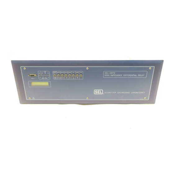
- Page 7 List of Figures Section 1: Introduction and Specifications Figure 1.1 SEL-587Z Front Panel......................1.2 Figure 1.2 SEL-587Z Hardware Block Diagram..................1.3 Figure 1.3 Protection Functions....................... 1.4 Figure 1.4 Bus Protection (simplified)....................1.5 Figure 1.5 Transformer Protection (simplified)..................1.5 Section 2: Installation Figure 2.1...
- Page 8 Figure 6.2 SEL-587Z to Computer......................6.4 Figure 6.3 SEL-587Z to Modem......................6.5 Figure 6.4 SEL-587Z to SEL-2020 or SEL-2030 Communications Processor........6.5 Section 7: ASCII Command Reference Figure 7.1 SHO Command Sample Display..................7.16 Figure 7.2 SHO L Command Sample Display..................7.17 Figure 7.3...
- Page 9 Equation 4.4..............................4.7 Section 9: Event Reports and SER Equation 9.1..............................9.3 Equation 9.2..............................9.16 Section 10: Testing and Troubleshooting Equation 10.1............................... 10.11 Equation 10.2............................... 10.13 Equation 10.3............................... 10.13 Equation 10.4............................... 10.13 Equation 10.5............................... 10.13 SEL-587Z Instruction Manual Date Code 20020903...
- Page 10 This page intentionally left blank...
-
Page 11: List Of Examples
Section 7: ASCII Command Reference Example 7.1 Access Level Attempt (password required) ................7.2 Example 7.2 Access Level Attempt (password not required) ..............7.3 Section 8: Front-Panel Interface Example 8.1 Display Points and Local Bit Configuration ................8.8 SEL-587Z Instruction Manual Date Code 20020903... - Page 12 This page intentionally left blank...
-
Page 13: Section 1: Introduction And Specifications
Section 1 Introduction and Specifications Introduction The SEL-587Z Relay is a high-impedance differential relay operating on the high-impedance principle. The unit provides three independent high- impedance elements, three independent overcurrent elements, two optoisolated inputs, four programmable output contacts, one alarm output contact, and two serial communication ports. -
Page 14: Overview
Introduction and Specifications Overview Overview Instruction This instruction manual applies to the SEL-587Z. If you are unfamiliar with the relay, read the following sections in the outlined order. Manual Section 1: Introduction and Specifications. Provides a brief overview of the capabilities and general specifications of the relay. -
Page 15: Figure 1.2 Sel-587Z Hardware Block Diagram
EIA-232 EIA-232/EIA-485* Port Port OUT1 OUT2 OUT3 OUT4 Real-Time Clock ALARM Power Supply Front Panel Low-Level Test Interface *Ordering option Figure 1.2 SEL-587Z Hardware Block Diagram. SEL-587Z Instruction Manual Date Code 20020903... -
Page 16: Sel-587Z Functions
Overcurrent element pickup settings and operating characteristics are independent from the differential element settings. When you use the SEL-587Z for transformer protection, the instantaneous overcurrent elements provide phase and ground overcurrent protection for bushing faults, while the time-overcurrent elements provide phase and ground protection for coordinating with other system protection. -
Page 17: Figure 1.4 Bus Protection (Simplified)
Introduction and Specifications SEL-587Z Functions Programmable OGIC ® The SEL-587Z is equipped with SEL control equations that allow you to design a custom tripping scheme. SEL control equation functions OGIC Output Contacts include timers, local and remote bits, tripping, event report triggering, and relay output contact control. - Page 18 This relay is available with a number of options: 5.22" (132.6 mm) 3U rack-mount package 6.65" (168.9 mm) panel-mount package 6.65" (168.9 mm) projection panel-mount package 1 A or 5 A nominal current inputs One (2500 J) or two MOVs (5000 J) SEL-587Z Instruction Manual Date Code 20020903...
-
Page 19: Specifications
IEC 61000-4-5: 1995 250 V 0.20 A L/R = 40 ms Note: Make per IEEE C37.90: 1989; Breaking and Cyclic Capacity 2 kV line to line, 4 kV line to earth per IEC 60255-0-20: 1974. SEL-587Z Instruction Manual Date Code 20020903... -
Page 20: Section 2: Installation
16 samples per power system cycle and 30 multiples of pickup. Curves operate on definite-time for current greater than 30 multiples of pickup or 16 times nominal. Reset Characteristic: Induction-disk reset emulation or 1-cycle linear reset SEL-587Z Instruction Manual Date Code 20020903... -
Page 21: Section 2: Installation
Installation Introduction Design your installation using the mounting and connection information in this section. Options include rack, panel, or projection panel mounting. This section also includes information on configuring the relay for your application. SEL-587Z Instruction Manual Date Code 20020903... -
Page 22: Relay Mounting And Maintenance
Panel Mount We also offer the SEL-587Z in a panel-mount version for a clean look. Panel- mount relays have sculpted front-panel molding that covers all installation holes. See Figure 2.1 on page... -
Page 23: Figure 2.1 Relay Dimensions, Panel Cutout, And Drill Plan
Installation Relay Mounting and Maintenance Figure 2.1 Relay Dimensions, Panel Cutout, and Drill Plan. SEL-587Z Instruction Manual Date Code 20020903... -
Page 24: Rear-Panel Connections
Ground connection (terminal 217): tab size 0.250" x 0.032", screw size #6-32. Use 12 AWG (4 mm ) or heavier wire less than 6.6 feet (2 m) in length for this connection. Figure 2.2 Relay Rear Panel. SEL-587Z Instruction Manual Date Code 20020903... - Page 25 Connection to external power must comply with IEC 947-1 and IEC 947-3. Place an external switch, circuit breaker, or overcurrent device in the POWER leads for the SEL-587Z; this device must interrupt both the hot (H) and neutral (N) power leads. The maximum current rating for the power disconnect circuit breaker or overcurrent device (fuse) must be 20 A.
-
Page 26: Sel-587Z Relay Ac/Dc Connection Diagrams
Installation SEL-587Z Relay AC/DC Connection Diagrams SEL-587Z Relay AC/DC Connection Diagrams 52-1 52-2 52-3 52-4 SEL-587Z External 86-1 86-2 86-3 HI– HI– HI– Lock-Out Relay Figure 2.3 Example AC Connection for High-Impedance Bus Protection. 52-1 52-2 52-3 52-4 SEL-587Z SEL-587Z... -
Page 27: Figure 2.5 Example Dc Connection
Installation SEL-587Z Relay AC/DC Connection Diagrams OUT1 OUT2 OUT3 ALARM OUT4 TRIP FAIL OPEN (—) Figure 2.5 Example DC Connection. SEL-587Z Instruction Manual Date Code 20020903... -
Page 28: Circuit Board Jumpers And Battery
Installation Circuit Board Jumpers and Battery Circuit Board Jumpers and Battery Control The SEL-587Z has field-changeable jumpers that select the control voltage for two digital inputs. Refer to Section 1: Introduction and Specifications Voltage Jumpers details on operating voltage and current levels. -
Page 29: Figure 2.6 Input And Output Jumper Locations
Figure 2.7 on page 2.10. Main board jumper JMP13 controls the operation of output contact OUT4. It provides the option of a second alarm Alarm Contact output contact by changing the signal that drives output contact OUT4. SEL-587Z Instruction Manual Date Code 20020903... -
Page 30: Table 2.2 Required Position Of Jumper Jmp13 For Desired Output Contact Out4 Operation
Step 4. Grasp the black knob on the front of the draw-out assembly and pull the assembly from the relay chassis. Step 5. Locate the battery on the right-hand side of the relay main board. SEL-587Z Instruction Manual Date Code 20020903... - Page 31 Step 9. Replace the relay front panel and reenergize the relay. Step 10. Set the relay date and time (see DAT (Date) on page 7.8 in Section 7: ASCII Command Reference TIM (Time) on page 7.21 in Section 7: ASCII Command Reference). SEL-587Z Instruction Manual Date Code 20020903...
-
Page 32: Port Connector And Communications Cables
2.12 Installation Port Connector and Communications Cables Port Connector and Communications Cables For information on making communications port connections to the relay, see Section 6: Serial Port Communications. SEL-587Z Instruction Manual Date Code 20020903... -
Page 33: Section 3: Relay Elements
This section discusses the operation of the differential elements, blocking logic, and overcurrent elements. The section also presents recommendations for calculating protection element settings. Differential protection elements are discussed first, followed by overcurrent elements. SEL-587Z Instruction Manual Date Code 20020903... -
Page 34: High-Impedance Protection
The SEL-587Z provides three independent high-impedance elements, one for each phase. The relay also provides single- and three-phase overcurrent elements with negative- and zero-sequence calculated elements. The low-... -
Page 35: Section 3: Relay Elements
Differential Element Pickups (87A1P through 87C2P) Range: OFF, 20–800 V The SEL-587Z has three independent, high-impedance differential elements, each with two levels. Use differential elements 87A1, 87B1, and 87C1 for bus protection and elements 87A2, 87B2, and 87C2 for alarms. All six settings have the same range and are set in volts. -
Page 36: Figure 3.5 Equivalent Circuit For Through Fault
Use the highest possible CT ratio, particularly for very high fault currents. Calculate the voltage developed across the high-impedance element: ---- • • LEAD 50000 -------------- - • 0.82 • 178 V (nearest volt) Equation 3.2 SEL-587Z Instruction Manual Date Code 20020903... -
Page 37: Figure 3.6 Ct Characteristic
Set the high-impedance elements 87A1P = 87B1P = 87C1P = 267 V. Minimum Use the following equation to calculate the minimum primary current required to operate the relay for an internal fault: Internal Fault • • Equation 3.5 Operating Current SEL-587Z Instruction Manual Date Code 20020903... -
Page 38: Equation 3.6
To achieve better sensitivity for the minimum internal fault current, use CTs with the highest possible knee voltage to assure small CT exciting current (I The SEL-587Z has a built-in high-value resistor (2000 ohm) that provides good sensitivity with a small relay current (I... -
Page 39: Figure 3.7 Mov Characteristic
4.0 cycles or fewer. For exceeding 4.0 cycles. example, wire an output contact from the SEL-587Z to operate an 86 lock-out relay, which in turn shorts the inputs to the high-impedance elements. Do not rely on the circuit breaker to clear the fault current, because the circuit breaker operating time may exceed 4.0 cycles or may fail to open altogether. -
Page 40: Figure 3.9 Single-Zone, Five Circuit Breaker Application (Simplified)
(87n2, n = A, B, C) to a low value to detect this condition. You can activate an alarm after a short time delay (minutes), block the trip elements after a longer time delay (minutes or hours), or both. SEL-587Z Instruction Manual Date Code 20020903... -
Page 41: Figure 3.10 Overcurrent Elements In Differential Circuit (One Phase Shown)
MOV failure during external faults (with one of the CTs saturating) or bus faults. However, the 50/51 elements provide back-up bus protection should the MOV fail during a heavy bus fault. SEL-587Z Instruction Manual Date Code 20020903... -
Page 42: Overcurrent Protection
Overcurrent Table 3.2 Table 3.3 summarize the overcurrent elements provided by the SEL-587Z. “Max” elements respond to the maximum value in any of the three Elements phases. “Phase” elements measure each phase separately (a measuring element per phase). Table 3.2 Instantaneous Overcurrent Elements... -
Page 43: Figure 3.11 Instantaneous Overcurrent Maximum Elements
Figure 3.12 Phase Overcurrent Elements. Instantaneous Negative-Sequence and Residual Figure 3.13 on page 3.12 shows the logic for the negative-sequence and residual overcurrent elements. Each element has two levels. The elements are not torque controlled. SEL-587Z Instruction Manual Date Code 20020903... -
Page 44: Figure 3.13 Negative-Sequence And Residual Overcurrent Elements
Reset Timing Torque-Control Switch Settings 51AP (pickup) 51AC (curve) 51AR 51ATD (time dial) 51ATC or 51ARS (reset E/M) control equation OGIC 51ATC (torque control) Figure 3.15 Inverse-Time Overcurrent (A-Phase) Element (B- and C-Phase are similar). SEL-587Z Instruction Manual Date Code 20020903... - Page 45 Time–Overcurrent Curve Equations on page 3.16) for the specific time-overcurrent characteristic equations. U.S. Curve Shapes U1–Moderately Inverse U2–Inverse U3–Very Inverse U4–Extremely Inverse U5–Short-Time Inverse IEC Curve Shapes C1–Class A (Standard Inverse) C2–Class B (Very Inverse) SEL-587Z Instruction Manual Date Code 20020903...
-
Page 46: Figure 3.16 Transformer With Grounded-Wye-Connected Winding
SEL-587 or SEL-387 Figure 3.16 Transformer With Grounded-Wye-Connected Winding. Set the SEL-587Z instantaneous overcurrent elements to detect high current faults, such as transformer bushing faults. Use time-overcurrent elements to detect transformer faults of lower current magnitude, faults not involving ground that the REF cannot detect, and excessive through currents caused by slow clearing external faults. - Page 47 Hot load pickup inrush occurs when a distribution circuit is energized shortly after being de-energized, such as in a feeder trip-reclose cycle. Hot load pickup inrush current that the SEL-587Z may see consists primarily of motor starting current from motor loads, incandescent and fluorescent lighting load inrush, and resistive heating element inrush.
-
Page 48: Equation 3.8
U.S. Moderately Inverse Curve: U1 Operating Time 0.0104 • 0.0226 ---------------------- 0.02 – Equation 3.8 Reset Time 1.08 ---------------- • Equation 3.9 – U.S. Inverse Curve: U2 Operating Time 5.95 • 0.180 ---------------- Equation 3.10 – SEL-587Z Instruction Manual Date Code 20020903... -
Page 49: Equation 3.11
0.02 – Reset Time 0.323 ---------------- • Equation 3.17 – I.E.C. Class A Curve (Standard Inverse): C1 Operating Time 0.14 ---------------------- • Equation 3.18 0.02 – Reset Time 13.5 ---------------- • Equation 3.19 – SEL-587Z Instruction Manual Date Code 20020903... -
Page 50: Equation 3.20
Equation 3.24 – Reset Time 120.0 ------------- - • Equation 3.25 – I.E.C. Short-Time Inverse Curve: C5 Operate Time 0.05 ---------------------- - • Equation 3.26 0.04 – Reset Time 4.85 ---------------- • Equation 3.27 – SEL-587Z Instruction Manual Date Code 20020903... -
Page 51: Figure 3.17 U.s. Moderately Inverse Curve: U1
60 (50) 5.00 4.00 30 (25) 2.00 15 (12.5) 1.00 6 (5) 0.50 3 (2.5) .5 .6 .7 .8 .9 1 5 6 7 Multiples of Pickup Figure 3.17 U.S. Moderately Inverse Curve: U1. SEL-587Z Instruction Manual Date Code 20020903... -
Page 52: Figure 3.18 U.s. Inverse Curve: U2
300 (250) 150 (125) 12.00 10.00 6.00 60 (50) 5.00 3.00 30 (25) 2.00 15 (12.5) 1.00 6 (5) 0.50 3 (2.5) .5 .6 .7 .8 .9 1 Figure 3.18 U.S. Inverse Curve: U2. SEL-587Z Instruction Manual Date Code 20020903... -
Page 53: Figure 3.19 U.s. Very Inverse Curve: U3
10.00 60 (50) 5.00 30 (25) 3.00 15 (12.5) 2.00 1.00 6 (5) 0.50 3 (2.5) .5 .6 .7 .8 .9 1 5 6 7 8 9 Figure 3.19 U.S. Very Inverse Curve: U3. SEL-587Z Instruction Manual Date Code 20020903... -
Page 54: Figure 3.20 U.s. Extremely Inverse Curve: U4
30 (25) 10.00 8.00 6.00 15 (12.5) 5.00 4.00 3.00 6 (5) 2.00 3 (2.5) 1.00 0.50 .5 .6 .7 .8 .9 1 6 7 8 9 Figure 3.20 U.S. Extremely Inverse Curve: U4. SEL-587Z Instruction Manual Date Code 20020903... -
Page 55: Figure 3.21 U.s. Short-Time Inverse Curve: U5
60 (50) 15.00 12.00 30 (25) 8.00 6.00 15 (12.5) 4.00 3.00 2.00 6 (5) 1.00 3 (2.5) 0.50 .5 .6 .7 .8 6 7 8 9 Figure 3.21 U.S. Short-Time Inverse Curve: U5. SEL-587Z Instruction Manual Date Code 20020903... -
Page 56: Figure 3.22 I.e.c. Class A Curve (Standard Inverse): C1
60 (50) 0.50 0.40 30 (25) 0.20 15 (12.5) 0.10 0.05 6 (5) 3 (2.5) .5 .6 .7 .8 .9 1 5 6 7 8 9 Figure 3.22 I.E.C. Class A Curve (Standard Inverse): C1. SEL-587Z Instruction Manual Date Code 20020903... -
Page 57: Figure 3.23 I.e.c. Class B Curve (Very Inverse): C2
150 (125) 60 (50) 30 (25) 1 00 15 (12.5) 6 (5) 3 (2.5) 0.05 .5 .6 .7 .8 .9 1 6 7 8 9 Figure 3.23 I.E.C. Class B Curve (Very Inverse): C2. SEL-587Z Instruction Manual Date Code 20020903... -
Page 58: Figure 3.24 I.e.c. Class C Curve (Extremely Inverse): C3
15 (12.5) 6 (5) 1.00 0.90 0.80 0.70 3 (2.5) 0.50 0.40 0.30 0.20 0.10 0.05 .5 .6 .7 .8 .9 1 6 7 8 9 Figure 3.24 I.E.C. Class C Curve (Extremely Inverse): C3. SEL-587Z Instruction Manual Date Code 20020903... -
Page 59: Figure 3.25 I.e.c. Long-Time Inverse Curve: C4
15000 (12500) 6000 (5000) 3000 (2500) 1500 (1250) 600 (500) 300 (250) 1.00 0.80 0.70 150 (125) 0.60 0.50 0.40 0.30 60 (50) 0.20 30 (25) 0.10 0.05 Figure 3.25 I.E.C. Long-Time Inverse Curve: C4. SEL-587Z Instruction Manual Date Code 20020903... -
Page 60: Figure 3.26 I.e.c. Short-Time Inverse Curve: C5
15 (12.5) 0.70 0.60 0.50 0.40 0.30 6 (5) 0.20 3 (2.5) 0.10 0.05 .5 .6 .7 .8 .9 5 6 7 8 9 Multiples of Pickup Figure 3.26 I.E.C. Short-Time Inverse Curve: C5. SEL-587Z Instruction Manual Date Code 20020903... -
Page 61: Demand Ammetering
Relay Elements 3.29 Demand Ammetering Demand Ammetering The SEL-587Z provides demand and peak demand ammetering for the following values: Currents I Input currents (A primary) A,B,C Residual ground current (A primary; IG = 3I0 = IA + IB + IC) -
Page 62: Figure 3.27 Response Of Thermal Demand Ammeter To A Step Input (Setting Dmtc = 15 Minutes)
1.0 per- unit value. This voltage rise across the capacitor is analogous to the response of the thermal demand ammeter in Figure 3.27 on page 3.30 (bottom) to the step current input (top). SEL-587Z Instruction Manual Date Code 20020903... -
Page 63: Table 3.4 Transformer Detail
(bottom) is at 90 percent (0.9 per unit) of full applied value (1.0 per unit) after a time period equal to setting DMTC = 15 minutes, referenced to when the step current input is first applied. The SEL-587Z updates thermal demand values approximately every two seconds. Setting... -
Page 64: Table 3.5 Temperature Parameters (Ieee C57.91: 1995)
Equation 3.31. – æ ----------- - ö θ ç ÷ 1.09 • – CHAR è ø 0.69 A Equation 3.31 The thermal demand element is calculated as shown in Equation 3.32 on page 3.33. SEL-587Z Instruction Manual Date Code 20020903... -
Page 65: Equation 3.32
– DMTC æ ö PDEMP -------------------- - • – -------------------- - è ø æ ö – --------------- - • – --------- - è ø 1.25 168 min (or 1.4 time constants) Equation 3.34 SEL-587Z Instruction Manual Date Code 20020903... - Page 66 This page intentionally left blank...
-
Page 67: Section 4: Control Logic
Introduction This section describes the various components of control logic available in the SEL-587Z Relay, both fixed and configurable. For ease of applying the relay, certain commonly used logic functions, known as fixed logic, are already programmed in the relay. Although fixed logic cannot be changed, most of the fixed logic includes options that provide flexibility for different applications. -
Page 68: Optoisolated Inputs
Relay variable (i.e., Relay Word bit, SEL control equation) = IN1 OGIC You can initiate an event report in the SEL-587Z when any of the feeders trip. Step 1. After wiring the feeder initiating contacts in parallel, connect the circuit to IN1. -
Page 69: Figure 4.2 Breaker-And-A-Half Bus
Figure 4.2, with an Examples SEL-587Z installed on each bus. Optoisolated input IN2 triggers the SEL-587Z to protect against bus faults, with a trip output contact from the relay operating an external 86 lockout relay. SEL-587Z SEL-587Z Figure 4.2 Breaker-and-a-Half Bus. -
Page 70: Section 4: Control Logic
SV8 = IN2 Variable SV8 OGIC The output of the timer (Relay Word bit SV8T) can then be used in place of Relay Word bit IN1; see Example 4.2 on page 4.3. SEL-587Z Instruction Manual Date Code 20020903... -
Page 71: Local Control Switches (Nlbn, Slbn, Clbn, Plbn)
Logic State NLBn “Name” LBn–Enable Switch CLOSED SLBn “Set” Local Bit LBn logical 1 OPEN CLBn “Clear” Local Bit LBn logical 0 MOMENTARY PLBn “Pulse” Local Bit LBn logical 1 for one processing interval SEL-587Z Instruction Manual Date Code 20020903... -
Page 72: Table 4.2 Local Bit Functions
“NA” for the setting (see Section 5: Setting the Relay). The local bit that is “driven” by this inoperable local control switch is fixed at logical 0. SEL-587Z Instruction Manual Date Code 20020903... -
Page 73: Table 4.4 Local Bit Lb3 Used As Bus Zone On/Off Switch
OFF position (corresponding local bit is still deasserted to logical 0) when power is restored. This is like a traditional installation with front-panel control switches. If power is lost to the panel, the front-panel control switches remain in position. SEL-587Z Instruction Manual Date Code 20020903... - Page 74 If the local control switch is made inoperable because of a settings change, the corresponding local bit is fixed at logical 0, regardless of the local bit state before the settings change. SEL-587Z Instruction Manual Date Code 20020903...
-
Page 75: Remote Control Switches
The remote control switches come back in the OFF position (corresponding remote bit is deasserted to logical 0) when power is restored to the relay. SEL-587Z Instruction Manual Date Code 20020903... - Page 76 OFF position (corresponding remote bit is deasserted to logical 0) before a settings change, it will come back in the OFF position (corresponding remote bit is still deasserted to logical 0) after the settings change. SEL-587Z Instruction Manual Date Code 20020903...
-
Page 77: Sel Ogic Control Equations
1 or 0. control equation settings are the inputs for the logic in many of the OGIC figures in this section. See the SEL-587Z Settings Sheets Section 5: Setting the Relay for a listing and short description of each of the SEL... -
Page 78: Table 4.6 Sel Ogic Control Equation Logic
As many as 250 Relay Word bits can be used to create SEL control OGIC equation settings. You can build the equations using Relay Word bits in combination with the SEL control equation operators listed in Table 4.5 OGIC on page 4.11. SEL-587Z Instruction Manual Date Code 20020903... -
Page 79: Table 4.7 Processing Order Of Relay Elements And Logic (Top To Bottom)
Trip Logic (TR1, 2, 3; ULTR1, 2 , 3) TRIP1, TRIP2, TRIP3 Close Logic (52A, CL, ULCL) CLOSE, CF Control Equation SV1–SV14, SV5T–SV14T OGIC Variables/Timers (SV1–SV14) Output Contacts (OUT1–OUT4) OUT1–OUT4 Display Points (DP1–DP8) Event Report Triggers (ER1, ER2) SEL-587Z Instruction Manual Date Code 20020903... -
Page 80: Sel Ogic Control Equation Variables/Timers
SV6PU SV11PU SV6T SV11T SV6DO SV11DO SV12 SV12 SV7PU SV12PU SV7T SV12T SV7DO SV12DO SV13 SV13 SV13PU SV8PU SV8T SV13T SV8DO SV13DO SV14 SV14 SV14PU SV14T SV14DO Figure 4.5 SEL Control Equation Variables/Timers. OGIC SEL-587Z Instruction Manual Date Code 20020903... -
Page 81: Example 4.8 Transformer Settings Example
Control Logic 4.15 Control Equation Variables/Timers OGIC EXAMPLE 4.8 Transformer Settings Example When the SEL-587Z is used as transformer protection, configure a dedicated breaker failure protection element as follows (see Figure 4.6): SV6 = TR1*50P1 Variable SV6 OGIC SV7 = TR1*50P1... -
Page 82: Trip Logic (Trn, Ultrn, Tdurd)
Once Relay Word bit TRIPn is asserted to logical 1, it remains asserted at logical 1 until both of these conditions are true: Trip Duration Timer stops timing (output of the TDURD timer goes to logical 0). control equation setting TRn deasserts to logical 0. OGIC SEL-587Z Instruction Manual Date Code 20020903... - Page 83 ULTRn does not assert to logical 1 to automatically deassert the TRIP Relay Word bit instead. EXAMPLE 4.9 Trip Logic SEL Control Equation Settings OGIC See the SEL-587Z Settings Sheets Section 5: Setting the Relay setting ranges. The following is an example of using SEL control equations in OGIC setting the trip, output, and unlatch functions.
-
Page 84: Close Logic (Cl, Ulcl, 52A, Cfd)
The Close Failure Timer is inoperative if setting CFD = 0. Then, the CLOSE Relay Word bit can be deasserted to logical 0 only if either of the following occurs: The unlatch close condition asserts (ULCL = logical 1). The circuit breaker closes (52A = logical 1). SEL-587Z Instruction Manual Date Code 20020903... -
Page 85: Example
Close Logic (CL, ULCL, 52A, CFD) EXAMPLE 4.10 Close Logic S Control Equation Settings ELOGIC See the SEL-587Z Settings Sheets Section 5: Setting the Relay setting ranges. control equation setting CL is set with local bit LB4. Local bit OGIC LB4 closes directly (operates as a manual close switch via the front panel). -
Page 86: Output Contacts
Relay Word bit (OUT1 through OUT4) to logical 1. The assertion of SEL control equation setting OUTm (m = 1 through 4) to OGIC logical 1 also asserts the corresponding Relay Word bit OUTm (m = 1 through 4) to logical 1. SEL-587Z Instruction Manual Date Code 20020903... - Page 87 Output Contact Serial Example Output OGIC Port Control Equation Relay Word Relay Word Bit Contact Coil Output Terminal Commands* Settings* Bits States States Contacts States open OUT1 OUT1 logical 0 de-energized OUT1 PULSE OUT1 Contact (a) closed OUT2 OUT2 logical 1 energized OUT2 PULSE OUT2...
- Page 88 ALARM Relay Word bit momentarily asserts to logical 1. Also, when the relay enters Access Level 2, the ALARM Relay Word bit momentarily asserts to logical 1 (and the ALARM output contact coil is de- energized momentarily). SEL-587Z Instruction Manual Date Code 20020903...
-
Page 89: Rotating Display
SCADA contacts, etc., to indicate such conditions as circuit breaker open/closed. See Section 8: Front-Panel Interface for more information on the rotating display. SEL-587Z Instruction Manual Date Code 20020903... -
Page 90: Front-Panel Target Leds
Refer to Figure 1.1 on page 1.2 in Section 1: Introduction and Specifications for the arrangement of the target LEDs on the front panel of the SEL-587Z. Table 4.8 lists the front-panel targets. The relay updates these targets during a relay trip event. -
Page 91: Section 5: Setting The Relay
Setting the Relay Introduction This section contains tables of relay settings for the SEL-587Z Relay. The relay hides some settings based upon other settings. If you set an enable setting to OFF, for example, the relay hides all settings associated with that enable setting. -
Page 92: Settings Changes Via The Serial Port
When settings are complete, the relay displays the new settings and prompts for approval to enable them. Answer Y <Enter> to enable the new settings. While the active settings are updated (about one second), the relay is disabled, and the ALARM contact closes. SEL-587Z Instruction Manual Date Code 20020903... -
Page 93: Settings Changes Via The Front Panel
Use the corresponding relay and port settings sheets that follow in this section when making these settings via the front panel. Refer to Figure 8.1 on page 8.2 in Section 8: Front-Panel Interface for information about front-panel communications. SEL-587Z Instruction Manual Date Code 20020903... -
Page 94: Identifier And System Parameter Settings
400. For this example, enter a value of 400. System Frequency (NFREQ) and Phase Rotation (PHROT) Use the relay settings NFREQ and PHROT to configure the SEL-587Z to your specific system. Set NFREQ equal to your nominal power system frequency, either 50 Hz or 60 Hz. -
Page 95: Sel-587Z Settings Sheets
Date _______________ SEL-587Z Settings Sheets 1 of 11 Relay Settings (SET Command) SEL-587Z Settings Sheets Relay Settings (SET Command) Identifier Labels Relay Identifier (12 characters) (0–9, A–Z, -, /, ., space) Terminal Identifier (12 characters) (0–9, A–Z, -, /, ., space) Current Transformer Ratios Phase (IA, IB, IC) CT Ratio (1–6000) - Page 96 2 of 11 SEL-587Z Settings Sheets Date________________ Relay Settings (SET Command) Single-Phase Instantaneous Overcurrent Elements 50A1–50C2 A Phase Inst. Pickup (OFF, 0.5–80.0 A) (5 A nominal) (OFF, 0.1–16.0 A) (1 A nominal) 50A1P A Phase Inst. Pickup (OFF, 0.5–80.0 A) (5 A nominal) (OFF, 0.1–16.0 A) (1 A nominal)
- Page 97 Date _______________ SEL-587Z Settings Sheets 3 of 11 Relay Settings (SET Command) B Phase Time-Overcurrent Pickup (OFF, 0.5–16.0 A) (5 A nominal) (OFF, 0.1–3.2 A) (1 A nominal) 51BP B Phase Time-Overcurrent Curve (U1–U5, C1–C5) 51BC B Phase Time-Overcurrent Time Dial 0.50–15.00 for curves U1–U5...
- Page 98 4 of 11 SEL-587Z Settings Sheets Date________________ Relay Settings (SET Command) Neg.-Seq. Inst. Pickup (OFF, 0.5–80.0 A) (5 A nominal) (OFF, 0.1–16.0 A) (1 A nominal) 50Q2P Negative-Sequence Time Overcurrent Element 51Q Neg.-Seq. Time Overcurrent Pickup (OFF, 0.5–16.0 A) (5 A nominal) (OFF, 0.1–3.2 A) (1 A nominal)
- Page 99 Date _______________ SEL-587Z Settings Sheets 5 of 11 Relay Settings (SET Command) SV8 Timer Dropout (0–54000.000 cycles in 0.125-cycle steps) SV8DO SV9 Timer Pickup (0–54000.000 cycles in 0.125-cycle steps) SV9PU SV9 Timer Dropout (0–54000.000 cycles in 0.125-cycle steps) SV9DO SV10 Timer Pickup (0–54000.000 cycles in 0.125-cycle steps) SV10PU SV10 Timer Dropout (0–54000.000 cycles in 0.125-cycle steps)
-
Page 100: Figure 4.7 Trip Logic
6 of 11 SEL-587Z Settings Sheets Date________________ Control Equation Settings (SET L Command) OGIC Control Equation Settings (SET L Command) OGIC Trip Logic Trip Conditions Trip Conditions Trip Conditions Unlatch Trip Conditions ULTR1 Unlatch Trip Conditions ULTR2 Unlatch Trip Conditions... - Page 101 Date _______________ SEL-587Z Settings Sheets 7 of 11 Control Equation Settings (SET L Command) OGIC Variable SV6 OGIC Variable SV7 OGIC Variable SV8 OGIC Variable SV9 OGIC Variable SV10 SV10 OGIC Variable SV11 SV11 OGIC Variable SV12 SV12 OGIC Variable SV13...
- Page 102 8 of 11 SEL-587Z Settings Sheets Date________________ Port Settings (SET P Command) Port Settings (SET P Command) NOTE: The RTSCTS setting does not appear if PROTO=LMD or MOD; PREFIX, ADDR, and SETTLE do not appear if PROTO=SEL or MOD; the SLAVE setting does not appear if PROTO=SEL or LMD. See SEL Distributed Port Switch Protocol (LMD) on page 6.10 in Section 6:...
- Page 103 Date _______________ SEL-587Z Settings Sheets 9 of 11 Text Settings (SET T Command) Text Settings (SET T Command) NOTE: Enter the following characters: 0–9, A–Z, -, /, ., space for each text label setting, subject to the specified character limit.
- Page 104 10 of 11 SEL-587Z Settings Sheets Date________________ Text Settings (SET T Command) Local Bit LB8 Name (14 characters) NLB8 Clear Local Bit LB8 Label (7 characters) CLB8 Set Local Bit LB8 Label (7 characters) SLB8 Pulse Local Bit LB8 Label (7 characters)
- Page 105 Date _______________ SEL-587Z Settings Sheets 11 of 11 Sequential Events Recorder Settings (SET R Command) Sequential Events Recorder Settings (SET R Command) NOTE: Sequential Events Recorder settings are comprised of three trigger lists. Each trigger list can include up to 24 Relay Word bits delimited by spaces or commas.
- Page 106 This page intentionally left blank...
-
Page 107: Section 6: Serial Port Communications
Serial Port Communications Introduction The SEL-587Z Relay is equipped with two serial communications ports, one on the rear panel and one on the front panel. One example of using these ports is to connect the front serial port to a computer for local communications and the rear port to a modem for remote communications. -
Page 108: Port Connector And Communications Cables
2400 bps Data Bits Parity Stop Bits To change the port settings, use the serial port SET P command (see SEL-587Z Settings Sheets Section 5: Setting the Relay ) or the front-panel {SET} pushbutton. Port Connections The 9-pin port connector is shown in Figure 6.1. -
Page 109: Table 6.2 Serial Communications Port Pin Function Definitions
Contact the factory for more information. For long-distance communications up to 500 meters and for electrical isolation of communications ports, use the SEL-2800 or SEL-2810 Fiber- Optic Transceivers. Contact SEL for details about these devices. SEL-587Z Instruction Manual Date Code 20020903... -
Page 110: Figure 6.2 Sel-587Z To Computer
"D" Subconnector "D" Subconnector Func. Func. Cable SEL-C227A SEL-587Z Relay *DTE Device 9-Pin Male 25-Pin Female "D" Subconnector "D" Subconnector Func. Func. *DTE = Data Terminal Equipment (Computer, Terminal, etc.) Figure 6.2 SEL-587Z to Computer. SEL-587Z Instruction Manual Date Code 20020903... -
Page 111: Figure 6.3 Sel-587Z To Modem
"D" Subconnector Func. Func. TXD (IN) DTR (IN) RXD (OUT) CD (OUT) *DCE = Data Communications Equipment (Modem, etc.) Figure 6.3 SEL-587Z to Modem. Cable SEL-C272A SEL-2020 or SEL-2030 SEL-587Z Relay 9-Pin Male 9-Pin Male "D" Subconnector "D" Subconnector Func. -
Page 112: Communications Protocols
QUI commands at Access Level 0. Enter the ACC command at the access level prompt: =ACC <Enter> The SEL-587Z goes to Access Level 1 [see ACC and 2AC (Access and 2Access) on page 7.2 in Section 7: ASCII Command Reference for more detail] when you enter the ACC command. - Page 113 While you are in Access Level 2, the relay recognizes any of the commands available in the lower access levels. Hardware SEL-587Z relays equipped with the EIA-232 port support RTS/CTS hardware handshaking. Protocol To enable hardware handshaking, use the SET P command (or front-panel {SET} pushbutton) to set RTSCTS = Y.
- Page 114 SEL LMD protocol. SEL Fast Meter Protocol SEL Fast Meter protocol supports binary messages to transfer metering and control messages. The protocol is described in Fast Meter on page 6.12. SEL-587Z Instruction Manual Date Code 20020903...
- Page 115 ASCII commands. Explanations of those commands are included in Section 7: ASCII Command Reference. The SEL-587Z provides Compressed ASCII versions of some of the relay’s ASCII commands. The Compressed ASCII commands allow an external device to obtain data from the relay, in a format which directly imports into spreadsheet or database programs, and which can be validated with a checksum.
-
Page 116: Sel Distributed Port Switch Protocol (Lmd)
6. Enter the sequence CTRL-X QUIT <CR> before entering the prefix character if all relays in the multidrop network do not have the same prefix setting. SEL-587Z Instruction Manual Date Code 20020903... -
Page 117: Sel Binary Protocols, Fast Meter, And Fast Operate
SEL Application Guide AG95-10, Configuration and Fast Meter Messages, is a comprehensive description of the SEL binary messages. The messages provided in the SEL-587Z are described in the following tables. Message Lists Table 6.4 Binary Message List... -
Page 118: Table 6.6 A5C0 Relay Definition Block
Scale factors in Fast Meter message Two scale factors Six analog input channels Four samples per channel Fourteen digital banks One calculation block 000C Analog channel offset 003C Time stamp offset 0044 Digital offset SEL-587Z Instruction Manual Date Code 20020903... - Page 119 FFFF Xs scale factor offset (none) IA channel index IB channel index IC channel index VA channel index (none) VB channel index (none) VC channel index (none) Reserved 1-byte checksum of all preceding bytes SEL-587Z Instruction Manual Date Code 20020903...
-
Page 120: Table 6.8 A5D1 Fast Meter Data Block
Analog channel name (IB) Analog channel type Scale factor type 0000 Scale factor offset in Fast Meter message 494300000000 Analog channel name (IC) Analog channel type Scale factor type 0000 Scale factor offset in Fast Meter message SEL-587Z Instruction Manual Date Code 20020903... -
Page 121: Table 6.10 A5D2/A5D3 Demand/Peak Demand Fast Meter Message
In response to the A5B9 request, the relay clears the Fast Meter (message A5D1) Status Byte. The SEL-587Z Status Byte contains one active bit, STSET (bit 4). The bit is set on power up and on settings changes. If the STSET bit is set, the external device should request the A5C1, A5C2, and A5C3 messages. -
Page 122: Table 6.12 A5E0 Fast Operate Remote Bit Control
1 byte Operate code: 00–07 clear remote bit RB1–RB8 20–27 set remote bit RB1–RB8 40–47 pulse remote bit for RB1–RB8 1 byte Operate validation: 4 • Operate code + 1 1-byte checksum of preceding bytes SEL-587Z Instruction Manual Date Code 20020903... -
Page 123: Table 6.13 A5E3 Fast Operate Breaker Control
The relay performs the specified breaker operation if the following conditions are true: Conditions 1–5 defined in the A5E0 message are true The BREAKER jumper is in place on the SEL-587Z main board The TDURD setting is nonzero ID Message In response to the ID command, the relay sends the following information: <STX>... - Page 124 SEL Binary Protocols, Fast Meter, and Fast Operate CONFIG is the phase input current and neutral input current scaling are both set to the same value since the SEL-587Z does not differentiate. Both the voltage and current input connection (wye vs. delta) are reported as N/A.
-
Page 125: Table 6.14 Communications Settings
4800, 9600, 19200 Parity PARITY O, E, N (O = Odd, E = Even, N = None) Stop Bits STOP 1, 2 Modbus Slave ID SLAVE 1–247 Modbus protocol is avaiable on the rear port only. SEL-587Z Instruction Manual Date Code 20020903... - Page 126 This page intentionally left blank...
-
Page 127: Section 7: Ascii Command Reference
ASCII Command Reference Introduction This section and the SEL-587Z Relay Command Summary on page 7.22 and at the end of this manual list the serial port commands alphabetically. Much of the information available using the serial port commands is also available via the front-panel pushbuttons. -
Page 128: Command Definitions
Access Level 1 password and blocks out a space for you to enter it: Password: ? @@@@@@ The relay is shipped with the default Access Level 1 password shown in the table under PAS (Password) on page 7.12. Enter the default password: Password: ? @@@@@@<Enter> SEL-587Z Instruction Manual Date Code 20020903... -
Page 129: Example 7.2 Access Level Attempt (Password Not Required)
The Compressed ASCII configuration message provides data for an external computer to extract data from other Compressed ASCII commands. To obtain Command— the configuration message for the Compressed ASCII commands available in an SEL relay, type: General Format CAS <CR> SEL-587Z Instruction Manual Date Code 20020903... - Page 130 A Compressed ASCII command may require multiple header and data configuration lines. If a Compressed ASCII request is made for data that are not available, (e.g., the history buffer is empty or invalid event request), the relay responds: “STX>"No Data Available","0668"<CR><ETX>. SEL-587Z Instruction Manual Date Code 20020903...
- Page 131 ASCII Command Reference Command Definitions CASCII Command Access Levels 0, 1, 2 Display the SEL-587Z Compressed ASCII configuration message by typing: CAS <CR> The relay sends: <STX>”CAS”,5,”YYYY”<CR> “CST”,1,”YYYY” <CR> “25H”,”MONTH”,”DAY”,”YEAR”,”HOUR”,”MIN”,”SEC”,”MSEC”,”87A”,’87B”, “87C’,”IA”,”IB”,”IC”, ”MOF”,”+5V_PS”,”+5V_REG”,”-5V_REG”,”+10V_PS”, ”-10V_PS”,“VBAT”,”TEMP”,”RAM”,”ROM”,”CR_RAM”,”EEPROM”,”YYYY” <CR> “1D”,”I”,”I”,”I”,”I”,”I”,”I”,”I”,”9S”,”9S”,”9S”,”9S”,”9S”,”9S”,”9S”,”9S”,”9S”,”9S”, “9S”,”9S”,”9S”,”9S”,”9S”,”9S”,”9S”,”9S”,”YYYY” <CR> “CHI”,1,”YYYY” <CR> “10H”,”REC_NUM”,”MONTH”,”DAY”,”YEAR”,”HOUR”,”MIN”,”SEC”,”MSEC”, “EVENT”,”TARGETS”,”YYYY”...
- Page 132 <ETX> (the data (xxxx) line is then repeated for each record) where: xxxx are the data values corresponding to the first line labels and yyyy is the 4-byte hex ASCII representation of the checksum. SEL-587Z Instruction Manual Date Code 20020903...
-
Page 133: Table 7.2 Sel-587Z Control Subcommands
CONTROL RB5: PRB 5 <Enter> =>> You must enter the same remote bit number in both steps in the command. If the bit numbers do not match, the relay responds “Invalid Command.” Table 7.2 SEL-587Z Control Subcommands Subcommand Description SRB n Set Remote Bit n (“ON”... - Page 134 EVE (Event) Access Levels 1, 2 Use the EVE command to view 15-cycle event reports. See Event Reports on page 9.2 in Section 9: Event Reports and SER for further details on retrieving event reports. SEL-587Z Instruction Manual Date Code 20020903...
- Page 135 DEVID reports the terminal ID as set by the TID setting. ® DEVCODE reports the Modbus code (53). The code is used for identification purposes by the SEL-2020/2030 and is not part of the Modbus subsystem. PARTNO reports the part number. SEL-587Z Instruction Manual Date Code 20020903...
- Page 136 Command Definitions CONFIG is the phase input current and neutral input current scaling are both set to the same value since the SEL-587Z does not differentiate. Both the voltage and current input connection (wye vs. delta) are reported as N/A.
- Page 137 C-phase current in primary amps Calculated residual current in primary amps Calculated negative-sequence current in primary amps Current magnitudes are displayed in primary amperes. The SEL-587Z reports the phase angles referenced to IA (IA phase angle = 0, positive phase angles leading).
-
Page 138: Table 7.3 Password Requirements And Default Passwords
(jumper JMP24 = OFF), the relay will not recognize the OPE command and responds “Aborted: No Breaker Jumper.” PAS (Password) Access Level 2 Your SEL-587Z is shipped with factory default passwords. Table 7.3 Password Requirements and Default Passwords Access Level Factory-Default Password... - Page 139 If JMP24 is not in place (jumper JMP24 = OFF), the relay does not accept the PUL command and responds “Aborted: No Breaker Jumper.” The relay generates an event report if you pulse the OUT1, OUT2, OUT3, or OUT4 contact. SEL-587Z Instruction Manual Date Code 20020903...
-
Page 140: Table 7.4 Set Command Parameters
Level 2 command. Table 7.4 SET Command Parameters Class Settings Relay settings SET L Logic settings SET P 1 Rear port settings SET P F Front port settings SET T Text settings SET R SER settings SEL-587Z Instruction Manual Date Code 20020903... - Page 141 Use the SHO command to view relay settings. The SHO command format is the following: SHO x y where: x is the settings class to display y is the name of the first setting to display SEL-587Z Instruction Manual Date Code 20020903...
-
Page 142: Table 7.5 Valid Sho Commands
SV10PU= 0.000 SV10DO= 0.000 SV11PU= 0.000 SV11DO= 0.000 SV12PU= 0.000 SV12DO= 0.000 SV13PU= 0.000 SV13DO= 0.000 SV14PU= 0.000 SV14DO= 0.000 NFREQ = 60 PHROT = ABC DATE_F= MDY Figure 7.1 SHO Command Sample Display. SEL-587Z Instruction Manual Date Code 20020903... -
Page 143: Figure 7.2 Sho L Command Sample Display
Sequential Events Recorder trigger lists: SER1 =87A1 87A2 87B1 87B2 87C1 87C2 SER2 =50P1 50A1 50A2 50B1 50B2 50C1 50C2 SER3 =51PT 51AT 51BT 51CT 51GT 51QT Figure 7.4 SHO R Command Sample Display. SEL-587Z Instruction Manual Date Code 20020903... -
Page 144: Figure 7.5 Sho T Command Sample Display
After the STA command is entered, the relay replies with the following status report: Date: 05/13/2002 Time: 14:17:01.359 STATION A FID=SEL-587Z-R100-V0-Z001001-D20020513 CID=00FF SELF TESTS W=Warn F=Fail +5V_PS +5V_REG -5V_REG +10V_PS -10V_PS VBAT 5.03 5.03 -5.03 10.35 -10.20 2.82 TEMP CR_RAM EEPROM 27.6 Relay Enabled => SEL-587Z Instruction Manual Date Code 20020903... -
Page 145: Table 7.6 Sta Command
The four top row targets correspond to the four left-most Relay Word bits, and the bottom four targets correspond to the four right-most Relay Word bits. The TAR command format is: TAR m n SEL-587Z Instruction Manual Date Code 20020903... -
Page 146: Table 7.7 Sel-587Z Relay Word And Its Correspondence To Tar Command And Front-Panel Leds
Interface), front-panel timeout is 15 minutes of front-panel pushbutton inactivity. Front-panel timeout takes the targets back to the normal front-panel target operation, also (like TAR 0). Table 7.7 SEL-587Z Relay Word and Its Correspondence to TAR Command and Front-Panel LEDs TAR 0... - Page 147 The most common reason for the relay not triggering an event is because the relay is not enabled. Use the STATUS command to verify relay status. Event Reports on page 9.2 in Section 9: Event Reports and SER for more information on event reports. SEL-587Z Instruction Manual Date Code 20020903...
-
Page 148: Sel-587Z Relay Command Summary
7.22 ASCII Command Reference SEL-587Z Relay Command Summary SEL-587Z Relay Command Summary Table 7.8 SEL-587Z Relay Commands Command Description 2ACCESS Go to Access Level 2 (complete relay monitoring and control) ACCESS Go to Access Level 1 (monitor relay) BNAME ASCII Names of all relay status bits (Fast Meter) -
Page 149: Section 8: Front-Panel Interface
Section 8 Front-Panel Interface Introduction This section describes how to get information, make settings, and execute control operations from the relay front panel. Also described in this section are the rotating display and display points. SEL-587Z Instruction Manual Date Code 20020903... -
Page 150: Front-Panel Operation
Front-Panel Interface Front-Panel Operation Front-Panel Operation Front-Panel A close-up view of the SEL-587Z Relay front panel is shown in Figure 8.1. It includes a 2-line, 16-character LCD; 8 LED target indicators; and 8 Operation pushbuttons for local control. Figure 8.1 Front-Panel User Interface. - Page 151 If it is incorrect, the relay will declare an “Invalid Password,” and allow another attempt. After three incorrect attempts, the relay will pulse the ALARM SEL-587Z Instruction Manual Date Code 20020903...
- Page 152 Section 7: ASCII Command Reference. For example, for more information on the metering values available via the front-panel {METER} pushbutton, refer to the MET (Meter) on page 7.11 in Section 7: ASCII Command Reference. SEL-587Z Instruction Manual Date Code 20020903...
-
Page 153: Figure 8.2 Front-Panel Pushbuttons-Primary Functions
Access Level 2 password through the front panel if main board jumper JMP22 is not in place. c Output contacts are pulsed for only one second from the front panel. Figure 8.2 Front-Panel Pushbuttons–Primary Functions. SEL-587Z Instruction Manual Date Code 20020903... -
Page 154: Figure 8.3 Front-Panel Pushbuttons-Secondary Functions
Scroll up on display; increment setting value Scroll down on display; decrement setting value The front-panel display indicates the arrow button to use (shows symbols: ← → ↑ ↓). Figure 8.3 Front-Panel Pushbuttons–Secondary Functions. SEL-587Z Instruction Manual Date Code 20020903... - Page 155 LEDs except for the EN LED, which is illuminated if the relay is enabled. While viewing or editing settings, the {TARGET RESET} pushbutton acts as a Help function, showing specific information about the displayed setting. SEL-587Z Instruction Manual Date Code 20020903...
-
Page 156: Local Control
2. Configure the second Local Bit as a breaker fail isolate ON/OFF switch, with the switch status visible on rotating display, using Display Points. Configure the third Local Bit as a breaker TRIP switch. SEL-587Z Instruction Manual Date Code 20020903... - Page 157 Next, configure the display point DP1: =>>SET L DP1 TE SELogic Control Equations: =0 [Enter the Relay Word bit whose status will be reported in the rotating display, i.e., LB2] ? LB2 ? END Save Changes(Y/N)? Y Settings saved SEL-587Z Instruction Manual Date Code 20020903...
- Page 158 There are no more local control switches configured. Press the right arrow pushbutton and scroll to the “output contact testing” function: Output Contact←→ Testing This front-panel function provides the same function as the serial port PULSE command (See Figure 8.2 on page 8.5). SEL-587Z Instruction Manual Date Code 20020903...
- Page 159 Technically, the MANUAL TRIP switch (being an OFF/ MOMENTARY type switch) is in the: TRIP position for one processing interval (1/8 cycle; long enough to assert the corresponding local bit LB3 to logical 1). SEL-587Z Instruction Manual Date Code 20020903...
- Page 160 If the BUSZONE switch is in the CLOSE position (switch closed) before the power outage, it will be in the same position after the outage when power is restored. SEL-587Z Instruction Manual Date Code 20020903...
-
Page 161: Rotating Display
If display point labels are also enabled, the “Press CNTRL for Local Control” displays for two seconds and then is followed by enabled display point labels in subsequent two-second rotations. The display is on a two-second rotation for each screen. SEL-587Z Instruction Manual Date Code 20020903... - Page 162 This page intentionally left blank...
-
Page 163: Section 9: Event Reports And Ser
Use the HISTORY command to obtain an index of these stored reports. Enable automatic messaging to configure the SEL-587Z Relay to send event report summaries of the serial port and to a printer, for example, to obtain a hard copy at the instant the report is triggered. -
Page 164: Event Reports
TR1 = 51PT + 51GT + 50P1 + LB3) does not have to be entered in SEL OGIC control equation settings ER1 or ER2. The assertion of Relay Word bit TRIP1 automatically triggers an event report. SEL-587Z Instruction Manual Date Code 20020903... -
Page 165: Equation 9.1
This event summary information is also contained in the corresponding event report. The identifiers, date, and time information is at the top of the event report, and the other information follows at the end. See Figure 9.2 on page 9.15. SEL-587Z Instruction Manual Date Code 20020903... -
Page 166: Table 9.1 Event Types
Reference). The event history contains the event report number, the date and time the event occurred, the event type, and relay targets. Use the event report history as an event report index, from which you can identify an event report for further examination. SEL-587Z Instruction Manual Date Code 20020903... - Page 167 If any of the relay settings or logic changes after an event was triggered, only the logic settings are displayed. Instead of the group settings, the relay shows the message “RELAY SETTINGS CHANGED SINCE EVENT.” SEL-587Z Instruction Manual Date Code 20020903...
-
Page 168: Table 9.3 Event Report Current Columns
9.15, indicating the sinusoidal nature of the waveforms. Digital Element Columns Various SEL-587Z Relay Word bits appear in the columns to the right of the analog columns. Table 9.4 on page 9.7 lists the elements that can appear in these columns. -
Page 169: Table 9.4 Digital Element Columns
Phase time-overcurrent element deasserted and fully reset Phase time-overcurrent element picked up and timing Phase time-overcurrent element picked up and timed out Phase time-overcurrent element is not picked up but timing element is asserted SEL-587Z Instruction Manual Date Code 20020903... - Page 170 Residual ground time-overcurrent element picked up and timing Residual ground time-overcurrent element picked up and timed out Residual ground time-overcurrent element is not picked up but timing element is asserted SEL-587Z Instruction Manual Date Code 20020903...
- Page 171 50C1 and 50A1 picked up Level 1 single-phase instantaneous overcurrent element 50A1 picked up Level 1 single-phase instantaneous overcurrent element 50B1picked up Level 1 single-phase instantaneous overcurrent element 50C1 picked up SEL-587Z Instruction Manual Date Code 20020903...
- Page 172 Lcl 56 LB5, LB6 Local bit LB5 asserted Local bit LB6 asserted Both LB5 and LB6 asserted Lcl 78 LB7, LB8 Local bit LB7 asserted Local bit LB8 asserted Both LB7 and LB8 asserted SEL-587Z Instruction Manual Date Code 20020903...
- Page 173 SV6T asserted SV 7T SV7, SV7T control OGIC equation variable SV7 asserted; timer not timed out control OGIC equation variable SV7 asserted and timer SV7T asserted control OGIC equation variable SV7 deasserted; timer SV75T asserted SEL-587Z Instruction Manual Date Code 20020903...
- Page 174 SV12T asserted SV 13T SV13, SV13T control OGIC equation variable SV13 asserted; timer not timed out control OGIC equation variable SV13 asserted and timer SV13T asserted control OGIC equation variable SV13 deasserted; timer SV13T asserted SEL-587Z Instruction Manual Date Code 20020903...
-
Page 175: Table 9.2 Event Report
* symbol takes precedence and is displayed. Because the relay samples at 1/8-cycles, the 1/4-cycle report contains only half of the processed information. To ensure the asterisk (*) and arrow (>) appear in the event report, use the 1/8-cycle report. SEL-587Z Instruction Manual Date Code 20020903... - Page 176 SLB7 PLB7 NLB8 CLB8 SLB8 PLB8 DP1_1 = DP1_0 = DP2_1 = DP2_0 = DP3_1 = DP3_0 = DP4_1 = DP4_0 = DP5_1 = DP5_0 = DP6_1 = DP6_0 = (Continued on next page) SEL-587Z Instruction Manual Date Code 20020903...
-
Page 177: Figure 9.2 Example Event Report (1/4-Cycle Sample)
(1/8-cycle reports) by using every other row of analog values. Use the column data in an event report to calculate phasor values. You can use a calculator to convert rectangular data to phasor data. SEL-587Z Instruction Manual Date Code 20020903... -
Page 178: Equation 9.2
87A column is 823.6 ∠ 99.6 ° V. The present sample of the sample pair (X = –138) is a scaled instantaneous voltage value (divided by ) that relates to the rms phasor voltage value by the following expression: cos 99.6 ° – 823.6 • Equation 9.2 SEL-587Z Instruction Manual Date Code 20020903... -
Page 179: Sequential Events Recorder (Ser) Report
The latest 512 rows of the SER report are stored in nonvolatile memory. Row 1 is the most recently triggered row, and row 512 is the oldest. These lines are SER Rows accessed with the SER command in the following different ways: SEL-587Z Instruction Manual Date Code 20020903... -
Page 180: Table 9.5 Accessing Ser Report
(top) of the report and the oldest row (date 1/5/96) at the end (bottom) of the report. Reverse chronological pro- gression through the report is down the page and in ascending row number. SEL-587Z Instruction Manual Date Code 20020903... -
Page 181: Table 9.6 Ser Report Additional Columns
Time (24-hour time) that the SER report row was triggered The SER report analog columns (87A, 87B, 87C, IA, IB, IC) display magnitude values (currents in primary), rather than sampled current values, as the event report current columns do. SEL-587Z Instruction Manual Date Code 20020903... -
Page 182: Figure 9.3 Example Sequential Events Recorder (Ser) Report
Relay newly powered up or settings changed 0 ..2....T..1b.1 10/05/2001 18:42:37.324 Relay newly powered up or settings changed 0 ........Figure 9.3 Example Sequential Events Recorder (SER) Report. SEL-587Z Instruction Manual Date Code 20020903... -
Page 183: Section 10: Testing And Troubleshooting
Introduction Use this section for determining and establishing test routines for the SEL-587Z Relay. Included are discussions on testing philosophies, methods, and tools. Example test procedures are shown for the overcurrent elements, differential elements, and metering. Relay troubleshooting procedures are listed at the end of the section. -
Page 184: Testing Methods And Tools
Section 7: ASCII Command Reference. Low-Level The SEL-587Z has a low-level test interface between the calibrated input module and the separately calibrated processing module. You test the relay in Test Interface either of two ways: By applying ac signals to the relay inputs (conventional... -
Page 185: Figure 10.1 Low-Level Test Interface
For an “a” contact, when the condition asserts, the output contact closes. When the condition deasserts, the output contact opens. For a “b” contact, when the condition asserts, the output contact opens. When the condition deasserts, the output contact closes. SEL-587Z Instruction Manual Date Code 20020903... - Page 186 With the SET R command, put the element name in the SER1, SER2, or SER3 setting. Whenever an element asserts or deasserts, a time stamp is recorded. View the SER report with the SER command. Clear the SER report with the SER C command. SEL-587Z Instruction Manual Date Code 20020903...
-
Page 187: Acceptance Testing
Acceptance Testing SEL performs detailed acceptance testing on all new relay models and versions. We are certain that your SEL-587Z meets published specifications. Even so, you can perform acceptance testing on a new relay model to become familiar with the relay operating theory and settings; this familiarity helps you apply the relay accurately and correctly. -
Page 188: Figure 10.2 Relay Part Number And Hardware Identification Sticker
Level 1 password and press <Enter>. The => prompt should appear, indicating that you have established communications at Access Level 1. Step 4. Purpose: Verify relay self-test status. Method: Type STA <Enter>. The following display should appear on the terminal: SEL-587Z Instruction Manual Date Code 20020903... -
Page 189: Figure 10.3 Sta Command
Step 5. Purpose: View factory settings entered before shipment. Method: The relay is shipped with factory settings; type SHO <Enter> to view the settings. The SEL-587Z Settings Sheets Section 5: Setting the Relay include a complete description of the settings. The terminal display should look similar to the following: =>>SHO... - Page 190 Step 1. With applied currents of 1A secondary per phase and a current transformer ratio of 120:1 (assuming setting CTR = 120), the displayed line currents should be close to 120 amperes primary. SEL-587Z Instruction Manual Date Code 20020903...
-
Page 191: Figure 10.5 Test Connections For Balanced Load With Three-Phase Current Sources
Source 1 Source 2 Source 3 SEL-587Z (partial) Figure 10.5 Test Connections for Balanced Load With Three-Phase Current Sources. Current Current Source 1 Source 2 SEL-587Z (partial) Figure 10.6 Test Connections With Two-Phase Current Sources. SEL-587Z Instruction Manual Date Code 20020903... -
Page 192: Table 3.2 Instantaneous Overcurrent Elements
Method: Execute the TARGET command (i.e., TAR 3 same procedure to test all instantaneous overcurrent elements <Enter>). The SEL-587Z now displays the state of several for each phase. overcurrent elements on the front-panel LED and LCD display. More overcurrent elements are on the next row; to view their status, type in TAR 4<Enter>. -
Page 193: Equation 10.1
Method: Repeat steps 1 through 4 for each time element listed Table 10.3 on page 10.12 for each phase. Remember to set the SER for the appropriate elements and apply current to the appropriate phase. SEL-587Z Instruction Manual Date Code 20020903... -
Page 194: Table 3.3 Inverse-Time Overcurrent Elements
Time Dial 51QTD 51QT (timed out) Electromechanical Reset 51QRS Phase The SEL-587Z has many phase overcurrent elements as shown in Table 10.2 on page 10.10 Table 10.3. Two kinds of elements are available: elements Overcurrent that operate based on a comparison between the maximum phase current... -
Page 195: Equation 10.2
These tests were outlined previously in this section. Residual Ground The SEL-587Z has three residual ground overcurrent elements. They all operate based on a comparison between a residual calculation of the three- Overcurrent phase inputs and the residual ground overcurrent setting. The residual... -
Page 196: Table 10.4 Instantaneous Overcurrent Elements And Corresponding Settings/Relay Word Bits/Tar Commands
Differential Element A-Phase Level 2 87A2P 87A2 Differential Element B-Phase Level 1 87B1P 87B1 Differential Element B-Phase Level 2 87B2P 87B2 Differential Element C-Phase Level 1 87C1P 87C1 Differential Element C-Phase Level 2 87C2P 87C2 SEL-587Z Instruction Manual Date Code 20020903... -
Page 197: Commissioning Testing
10.15 Commissioning Testing Commissioning Testing SEL performs a complete functional check and calibration of each SEL-587Z before shipment so that your relay operates correctly and accurately. You should perform commissioning tests to verify proper connection of the relay to the power system and all auxiliary equipment: Check control signal inputs and outputs. -
Page 198: Maintenance Testing
Test all relay features/power system components that did not operate during an actual fault within the past maintenance interval. You can use the SEL-587Z reporting features as maintenance tools. Periodically compare the relay METER command output to other meter readings on a line to verify that the relay measures currents and voltages correctly and accurately. -
Page 199: Relay Self-Tests
Testing and Troubleshooting 10.17 Relay Self-Tests Relay Self-Tests The SEL-587Z runs a variety of self-tests. The relay takes the following corrective actions for out-of-tolerance conditions (see Table 10.6): The relay disables protection elements and trip/close logic. All output contacts are de-energized. The EN front-panel LED is extinguished. - Page 200 The following self-tests are performed by dedicated circuitry in the microprocessor and the SEL-587Z main board. Failures in these tests shut down the microprocessor and are not shown in the STATUS report.
-
Page 201: Relay Troubleshooting
Step 2. Relay or communications device at incorrect baud rate or other communication parameter incompatibility, including cabling error. Step 3. Relay serial port has received an XOFF, halting communications. Type <Ctrl>Q to send relay an XON and restart communications. SEL-587Z Instruction Manual Date Code 20020903... - Page 202 Step 1. Relay improperly set. Step 2. Improper test source settings. Step 3. CT input wiring error. Step 4. Analog input cable between transformer secondary and main board loose or defective. Step 5. Failed relay self-test. SEL-587Z Instruction Manual Date Code 20020903...
-
Page 203: Relay Calibration
Testing and Troubleshooting 10.21 Relay Calibration Relay Calibration The SEL-587Z is factory calibrated. If you suspect that the relay is out of calibration, please contact the factory. SEL-587Z Instruction Manual Date Code 20020903... -
Page 204: Factory Assistance
Factory Assistance Factory Assistance We appreciate your interest in SEL products and services. If you have questions or comments, please contact us at: Schweitzer Engineering Laboratories, Inc. 2350 NE Hopkins Court Pullman, WA USA 99163-5603 Tel: (509) 332-1890 Fax: (509) 332-7990 Internet: www.selinc.com... -
Page 205: Appendix A: Firmware And Manual Versions
Table A.1 lists the firmware versions, a description of modifications, and the instruction manual date code that corresponds to firmware versions for the SEL-587Z. The most recent firmware version is listed first. Table A.1 Firmware Revision History Firmware Identification (FID) Number... -
Page 206: Instruction Manual
Manual Change Information Removed Manual Change Information page from front of manual and incorporated information in this table. This manual differs from the previous versions as follows: 20020418 Initial Release. SEL-587Z Instruction Manual Date Code 20020903... -
Page 207: Appendix B: Firmware Upgrade Instructions
SEL occasionally offers firmware upgrades to improve the performance of your relay. Changing physical components to upgrade the relay firmware is unnecessary because the SEL-587Z Relay stores firmware in Flash memory. A firmware loader program called SEL resides in the relay. To upgrade... - Page 208 Note that you might later change this computer serial port selection to establish communication between your relay and your computer if this connection is unsuccessful. Step 2. Disconnect any other serial port connection. SEL-587Z Instruction Manual Date Code 20020903...
-
Page 209: Figure B.1 Establishing A Connection
These settings are SPEED (Bits per second), BITS, PARITY, STOP (Stop bits), and RTSCTS (Flow control). If computer settings do not match relay settings, change the computer settings to match relay settings. b. Click OK and press <Enter>. SEL-587Z Instruction Manual Date Code 20020903... -
Page 210: Figure B.3 Determining Communications Parameters For The Computer
You should see a screen and the Access Level 0 prompt similar to that in Figure B.5. The prompt appears when you press <Enter>. If this is successful, proceed to Save Settings and Other Data on page B.6. SEL-587Z Instruction Manual Date Code 20020903... -
Page 211: Figure B.5 Terminal Emulation Startup Prompt
You will see a dialog box similar to Figure B.7. Step 4. Change settings in the appropriate list boxes to match the settings you recorded in Step A.9 on page B.2 and click OK. SEL-587Z Instruction Manual Date Code 20020903... -
Page 212: Figure B.7 Correcting Communications Parameters
The relay preserves the settings and passwords during the firmware upgrade process. However, if relay power is interrupted during the firmware upgrade process, the relay can lose the settings. Make a copy of the original relay SEL-587Z Instruction Manual Date Code 20020903... - Page 213 BOOT responds to the terminal with the SEL action prompt !>. BOOT Step 3. Press <Enter> to confirm that the relay is in SEL BOOT You will see another !> SEL action prompt. BOOT SEL-587Z Instruction Manual Date Code 20020903...
-
Page 214: Figure B.8 Matching Computer To Relay Parameters
HyperTerminal reestablishes communication automatically the second time you click OK. Step 6. Press <Enter> to check for the SEL action prompt !> BOOT indicating that serial communication is successful. Figure B.8 Matching Computer to Relay Parameters. SEL-587Z Instruction Manual Date Code 20020903... -
Page 215: Figure B.9 Example Receive File Dialog Box
These files have an .s19 extension (e.g., r100587Z.s19). Figure B.10 Example Filename Identifying Old Firmware Version. For a successful download, you should see a dialog box similar Figure B.11. After the transfer, the relay responds, “Download completed successfully!” SEL-587Z Instruction Manual Date Code 20020903... -
Page 216: Figure B.11 Downloading Of Old Firmware
From the Transfer menu in HyperTerminal, choose Send File (Figure B.12). b. In the Filename text box, type the location and filename of your new firmware or use the Browse button to select the firmware file. SEL-587Z Instruction Manual Date Code 20020903... -
Page 217: Figure B.12 Selecting The New Firmware To Send To The Relay
If the EN LED is illuminated and the Access Level 0 prompt is visible, proceed to Verify Calibration, Status, and Metering on page B.13. If this is not the case, perform the following steps. SEL-587Z Instruction Manual Date Code 20020903... - Page 218 R_S command, contact the factory or your Technical Service Center for assistance. Step 5. Type Y<Enter>. The relay can take as long as two minutes to restore default settings. The relay then reinitializes, and the EN LED illuminates. SEL-587Z Instruction Manual Date Code 20020903...
- Page 219 Step 9. If these values do not match, check the relay settings and wiring. SEL-587Z Instruction Manual Date Code 20020903...
- Page 220 Step 2. Autoconfigure the SEL-20x0 port if you have an SEL-2020 or SEL-2030 Communications Processor connected to the relay. This step reestablishes automatic data collection between the SEL-20x0 Communications Processor and the SEL-587Z Relay. Failure to perform this step can result in automatic data collection failure when cycling communications processor power.
-
Page 221: Table C.1 Sel-587Z Relay Word Bit Summary
The Relay Word thus contains placeholders, the Relay Word bits, for each of the protection elements and logic conditions in the SEL-587Z Relay. Each Relay Word bit is updated every eighth-cycle. For more information on using Relay Word bits to progam the relay, see Control Equations on page 4.11 in Section 4:... -
Page 222: Appendix C: Relay Word Bits
50C2 Second single-phase instantaneous overcurrent element 50G1 First residual ground overcurrent element pickup 50G2 Second residual ground overcurrent element pickup 50Q1 First negative-sequence definite-time overcurrent element pickup 50Q2 Second negative-sequence definite-time overcurrent element pickup SEL-587Z Instruction Manual Date Code 20020903... -
Page 223: Table C.3 Relay Word Bits: High-Impedance Elements
Local Bit 8 Table C.5 Relay Word Bits: Remote Bits Name Description Remote Bit 1 Remote Bit 2 Remote Bit 3 Remote Bit 4 Remote Bit 5 Remote Bit 6 Remote Bit 7 Remote Bit 8 SEL-587Z Instruction Manual Date Code 20020903... -
Page 224: Table C.6 Relay Word Bits: Sel Ogic Control Equation Variables
Reserved for future use Table C.7 Relay Word Bits: Trip/Close Logic Name Description TRIP1 Trip 1 logic output TRIP2 Trip 2 logic output TRIP3 Trip 3 logic output CLOSE Close logic output Reserved for future use SEL-587Z Instruction Manual Date Code 20020903... -
Page 225: Table C.8 Relay Word Bits: Demand Elements
First neg.-seq. definite-time overcurrent element pickup 50Q2 Second neg.-seq. definite-time overcurrent element pickup A-phase time-overcurrent element pickup 51AR A-phase time-overcurrent element reset 51AT A-phase time-overcurrent element B-phase time-overcurrent element pickup 51BR B-phase time-overcurrent element reset 51BT B-phase time-overcurrent element SEL-587Z Instruction Manual Date Code 20020903... - Page 226 Open command OUT1 Output contact OUT1 OUT2 Output contact OUT2 OUT3 Output contact OUT3 OUT4 Output contact OUT4 PDEM Phase demand current above pickup setting QDEM Negative-sequence demand current above pickup setting Remote Bit 1 SEL-587Z Instruction Manual Date Code 20020903...
- Page 227 OGIC control equation variable timer input OGIC SV9T control equation variable timer output OGIC TRIP1 Trip 1 logic output TRIP2 Trip 2 logic output TRIP3 Trip 3 logic output SEL-587Z Instruction Manual Date Code 20020903...
- Page 228 This page intentionally left blank...
-
Page 229: Table D.1 Modbus Query Fields
Cyclical Redundancy Check (CRC) 2 bytes The SEL-587Z SLAVEID setting defines the device address. Set this value to a unique number for each device on the Modbus network. For Modbus communication to operate properly, no two slave devices may have the same address. -
Page 230: Appendix D: Modbus Rtu Communications Protocol Modbus Overview
Force Single Coil Preset Single Register Read Exception Status Loopback Diagnostic Preset Multiple Registers Scattered Register Read Exception The SEL-587Z sends an exception code under the conditions described in Table D.3. Responses Table D.3 SEL-587Z Modbus Exception Codes Exception Error Type... - Page 231 CRC. If the calculated CRC matches the CRC sent by the Check (CRC) SEL-587Z, the master device uses the data received. If there is not a match, the check fails and the message is ignored. The devices use a similar process when the master sends queries.
-
Page 232: Modbus Commands
Invalid Address Invalid number of bits to read Illegal Data Value (03h) Illegal Register Format error Illegal Data Value (03h) Bad Packet Format Please refer to Table D.9 on page D.8 for coil number assignments. SEL-587Z Instruction Manual Date Code 20020903... -
Page 233: Table D.5 02H Read Input Status Command
Error Code Returned Counter Increments Invalid bit to read Illegal Data Address (02h) Invalid Address Invalid number of bits to read Illegal Data Value (03h) Illegal Register Format error Illegal Data Value (03h) Bad Packet Format SEL-587Z Instruction Manual Date Code 20020903... -
Page 234: Table D.6 03H Read Holding Register Command
Error Code Returned Counter Increments Illegal register to read Illegal Data Address (02h) Invalid Address Illegal number of registers to read Illegal Data Value (03h) Illegal Register Format error Illegal Data Value (03h) Bad Packet Format SEL-587Z Instruction Manual Date Code 20020903... -
Page 235: Table D.7 04H Read Holding Register Command
Placeholder (00) 2 bytes CRC-16 The command response is identical to the command request. The coil numbers supported by the SEL-587Z are listed in Table D.9 on page D.8. The physical coils (Coils 1–5) are self-resetting. If the relay is disabled or the breaker jumper is not installed, it will respond with error code 4 (Device Error). -
Page 236: Table D.9 Sel-587Z Command Coils
Illegal Data Value (03h) Bad Packet Format 06h Preset The SEL-587Z uses this function to allow a Modbus master to write directly to a database register. These registers are used to write the command code and Single Register parameters for the command region, selecting the event number or channel number for Event data region and setting the Relay Date and Time. -
Page 237: Table D.10 06H Preset Single Register Command
Illegal Data Value (03h) Bad Packet Format 07h Read The SEL-587Z uses this function to allow a Modbus master to read the present status (get a “snapshot” view) of the relay and protected circuit by reading Exception eight predefined status bits. -
Page 238: Table D.12 08H Loopback Diagnostic Command
Illegal Data Value (03h) Bad Packet Format 08h Loopback The SEL-587Z uses this function to allow a Modbus master to perform a diagnostic test on the Modbus communications channel and relay. When the Diagnostic subfunction field is 0000h, the relay returns a replica of the received message. -
Page 239: Table D.13 10H Preset Multiple Registers Command
Illegal Data Value (03h) Illegal Write 64h Scattered The SEL-587Z uses this function to allow a Modbus master to read noncontiguous registers in a single request. A maximum of 100 registers can Register Read be read in a single query. -
Page 240: Table D.15 Sel-587Z Modbus Command Region
Table D.18 on page D.16. If function code 06h is used to write to a command code that has parameters, the parameters must be written before the command code. Table D.15 SEL-587Z Modbus Command Region Address Field 0090h Command Code... -
Page 241: Table D.16 Modbus Command Codes
Switches the serial port protocol to SEL-ASCII, the baud rate, parity, stop bits, and flow control remain the same. Parameter of Command code 11 is bit masked to allow you to manipulate several data regions simultaneously. SEL-587Z Instruction Manual Date Code 20020903... - Page 242 The Modbus Register Map (Table D.18 on page D.16) provides a feature that allows you to download complete event data via Modbus. The SEL-587Z Event Data stores the 10 latest 15-cycle, full-length event reports. Refer to Section 8: Event Reports for more detailed description.
-
Page 243: Table D.17 Assign Event Report Channel Using Address 00B2
00C1h. Then read the history of the specific event number you requested from the Modbus Map (Table D.18). If you select a history number for which there is no data available, 8000h will be returned. SEL-587Z Instruction Manual Date Code 20020903... -
Page 244: Modbus Map
2 = Fail Channel 87C 0034 –5000 5000 offset value Channel 87C 0035 – – – – – status message 0 = OK 1 = Warn 2 = Fail Channel IA 0036 –5000 5000 offset value SEL-587Z Instruction Manual Date Code 20020903... - Page 245 0 = OK 1 = Warn 2 = Fail 0042 –5_REG power –600 0.01 supply value –5_REG 0043 – – – – – power supply status message 0 = OK 1 = Warn 2 = Fail SEL-587Z Instruction Manual Date Code 20020903...
- Page 246 2 = Fail EEPROM status 004F – – – – – 0 = OK 2 = Fail 0050 Enable status – – – – – 0 = relay enabled 2 = relay disabled 0051–005F Reserved SEL-587Z Instruction Manual Date Code 20020903...
- Page 247 Reserved Demand Demand 0070 Amps 65535 current A-phase 0071 Demand Amps 65535 current B-phase 0072 Demand Amps 65535 current C-phase Demand 0073 Amps 65535 residual current I Demand 0074 Amps 65535 neg.-seq. current 3I SEL-587Z Instruction Manual Date Code 20020903...
- Page 248 0083 Date 0084 0085 yyyy 1992 2999 0086-008F Reserved Relay Time and Date 0090 (RW) Time (see NOTE 0091 (RW) 0092 (RW) Date 0093 (RW) 0094 (RW) 0095 (RW) yyyy 1992 2999 0096–009F Reserved SEL-587Z Instruction Manual Date Code 20020903...
- Page 249 8–15 are set to 1. Bit 0 = 0 if all of bits 8–15 are set to 0. Bits 1–7 = 0 Bit 8 = 51BT Bit 9 = 51B Bit 10 = 51AR Bit 11 = 51AT SEL-587Z Instruction Manual Date Code 20020903...
- Page 250 Bit 0 = 1 if any of bits 8–15 are set to 1. Bit 0 = 0 if all of bits 8–15 are set to 0. Bits 1–7 = 0 Bit 8 = 50Q2 SEL-587Z Instruction Manual Date Code 20020903...
- Page 251 Bits 1–7 = 0 Bit 8 = CF Bit 9 = CC Bit 10 = OC Bit 11 = IN2 Bit 12 = IN1 Bit 13 = * Bit 14 = * Bit 15 = * SEL-587Z Instruction Manual Date Code 20020903...
- Page 252 Bit 0 = 0 if all of bits 8–15 are set to 0. Bits 1–7 = 0 Bit 8 = SV8 Bit 9 = SV7 Bit 10 = SV6 Bit 11 = SV5 Bit 12 = SV4 SEL-587Z Instruction Manual Date Code 20020903...
- Page 253 8–15 are set to 1. Bit 0 = 0 if all of bits 8–15 are set to 0. Bits 1–7 = 0 Bit 8 = SV12T Bit 9 = SV11T SEL-587Z Instruction Manual Date Code 20020903...
- Page 254 Reserved History Records 00C0 Number of History Records History Selection 00C1 (RW) (see NOTE Event Time 00C2 millisec 00C3 00C4 00C5 Event Date 00C6 00C7 00C8 yyyy 2000 2999 Event Type 00C9 ASCII string SEL-587Z Instruction Manual Date Code 20020903...
- Page 255 5 1/4 cycle –32767 32767 00E8 5 1/2 cycle –32767 32767 00E9 5 3/4 cycle –32767 32767 00EA 6 cycle –32767 32767 00EB 6 1/4 cycle –32767 32767 00EC 6 1/2 cycle –32767 32767 SEL-587Z Instruction Manual Date Code 20020903...
- Page 256 13 3/4 cycle 0109 –32767 32767 14 cycle 010A –32767 32767 14 1/4 cycle 010B –32767 32767 14 1/2 cycle 010C –32767 32767 010D 14 3/4 cycle –32767 32767 010E 15 cycle –32767 32767 010F Reserved SEL-587Z Instruction Manual Date Code 20020903...
- Page 257 65535 Neg.-Seq. Current 0125 – 012F Reserved Maximum Current Limit 0130 Multiplier Volts –32767 32767 (Phase Voltage) 0131 Scale Exponent –4 0132 Multiplier Amps –32767 32767 (Phase Current) 0133 Scale Exponent –4 0134–013F Reserved SEL-587Z Instruction Manual Date Code 20020903...
- Page 258 NOTE 2. Registers (RW) are read/write registers. Registers (W) are write-only registers. Registers (R) are read-only registers. All other registers are read only. NOTE 3. Event Types ASCII CODE TRIP1 TRIP2 TRIP3 PULSE TRIG SEL-587Z Instruction Manual Date Code 20020903...
- Page 259 D.16) provides a feature that allows you to download complete event data or History data via Modbus. The SEL-587Z stores the 10 latest event reports and 10 latest event summaries (History data) in nonvolatile memory. The event report extraction will be through 20 channels. These channels...
- Page 260 This page intentionally left blank...
-
Page 261: Glossary
A list of standard numbers used to represent electrical protection and control Device Numbers relays. Standard device numbers include the following: Synchronism-check element Undervoltage Element Directional Elements Overcurrent Element Inverse-Time Overcurrent Element AC Circuit Breaker Overvoltage Element Definite-Time Overcurrent SEL-587Z Relay Date Code 20020903... - Page 262 To activate. To fulfill the logic or electrical requirements needed to operate a device. To set a logic condition to the true state (logical 1) of that condition. To apply a closed contact to an SEL-587Z Relay input. To close a normally open output contact. To open a normally closed output contact.
- Page 263 Current transformer ratio. Current The point of maximum current input to a current transformer; any change of Transformer Saturation input beyond the saturation point fails to produce any appreciable change in output. SEL-587Z Relay Date Code 20020903...
- Page 264 To clear a logic condition to its false state (logical 0). To open the circuit or open the contacts across an SEL-587Z Relay input. To open a normally open output contact. To close a normally closed output contact.
- Page 265 A device connected in parallel with paralleled CTs that form a differential Differential Relay protection zone. During an external fault, the high-impedance forces circulating fault current to flow through the saturated CT instead of the relay. SEL-587Z Relay Date Code 20020903...
- Page 266 The establishment of debounce time and assertion level. Instantaneous Meter Type of meter data presented by the SEL-587Z Relay that includes the present values measured at the relay ac inputs. The word “Instantaneous” is used to differentiate these values from the measurements presented by the demand and other meter types.
- Page 267 Peak Demand Metering Maximum demand and a time stamp for phase currents, negative-sequence and zero-sequence currents, and powers. The SEL-587Z Relay stores peak demand values and the date and time these occurred to nonvolatile storage once per day, overwriting the previously stored value if the new value is larger.
- Page 268 Represented by the / symbol. Root-mean-square. This is the effective value of the current and voltage measured by the relay, accounting for the fundamental frequency and higher- order harmonics in the signal. SEL-587Z Relay Date Code 20020903...
- Page 269 Supervisory control and data acquisition. A function that verifies the correct operation of a critical device subsystem Self-Test and indicates detection of an out-of-tolerance condition. The SEL-587Z Relay has self-tests that validate the relay power supply, microprocessor, memory, and other critical systems.
- Page 270 Overcurrent protection that operates at conditions exceeding a threshold of Overcurrent Element system unbalance. Z-Number That portion of the relay FID string that identifies the proper ERATOR software relay driver version and HMI driver version when creating or editing relay settings files. SEL-587Z Relay Date Code 20020903...
-
Page 271: Index
– communications protocols See also Jumpers EIA-232 Cleaning hardware flow control DATE Command Close Logic 4.18 pinout application example 4.19 Demand Metering 3.29 – 3.33 EIA-485 CLOSE command 4.18 See also Meter pinout SEL-587Z Instruction Manual Date Code 20020903... - Page 272 – Installation 2.12 trigger Maintenance Testing 10.16 dimensions Event Summary See also Testing panel mounting See also Event Menus rack mounting contents See Front Panel, menus ventilation event type Instantaneous Metering See Meter SEL-587Z Instruction Manual Date Code 20020903...
- Page 273 See also Jumpers Password rear panel Schweitzer Engineering Laboratories defaults 7.12 contact information 10.22 Serial Port Commands front panel See Commands Scrolling jumper See Front Panel, screen scrolling Setting See also Jumpers application example SEL-587Z Instruction Manual Date Code 20020903...
- Page 274 10.2 maintenance testing 10.16 – methods 10.2 10.4 – overcurrent elements 10.10 10.13 application example 10.10 10.11 self tests 10.17 test connections 10.9 10.14 with output contacts 10.3 with SER 10.4 SEL-587Z Instruction Manual Date Code 20020903...
-
Page 275: Sel-587Z Relay Command Summary
SEL-587Z Relay Command Summary SEL-587Z Relay Commands Command Description 2ACCESS Go to Access Level 2 (complete relay monitoring and control) ACCESS Go to Access Level 1 (monitor relay) BNAME ASCII Names of all relay status bits (Fast Meter) CASCII Generate the Compressed ASCII response configuration message... - Page 276 This page intentionally left blank...
Need help?
Do you have a question about the SEL-587Z and is the answer not in the manual?
Questions and answers